Transcription
Piling in layered ground: risks togroundwater and archaeologyScience Report SC020074/SRSCHO0906BLLT-E-E/P
The Environment Agency is the leading public body protecting and improving the environmentin England and Wales.It’s our job to make sure that air, land and water are looked after by everyone in today’s society,so that tomorrow’s generations inherit a cleaner, healthier world.Our work includes tackling flooding and pollution incidents, reducing industry’s impacts on theenvironment, cleaning up rivers, coastal waters and contaminated land, and improving wildlifehabitats.English Heritage is the Government’s statutory adviser on the historic environment. Our role isto champion and care for the historic environment which we do by: Improving understanding of the past through research and studyProviding conservation grants, advisory and education servicesIdentifying and helping to protect buildings and archaeological sites of national importanceMaintaining over 400 historic properties and making them accessible to the broadestpossible public audienceMaintaining the National Monuments Record as the central publicly accessible archive forthe historic environment in England.This report is the result of research jointly funded by the Environment Agency’s ScienceProgramme, and the English Heritage Historic Environment Enabling Programme (HEEP).Published by:Environment Agency, Rio House, Waterside Drive, Aztec West,Almondsbury, Bristol, BS32 4UDTel: 01454 624400 Fax: 01454 624409www.environment-agency.gov.ukISBN: 1844325962 Environment Agency October 2006All rights reserved. This document may be reproduced with priorpermission of the Environment Agency.The views expressed in this document are not necessarilythose of the Environment Agency.This report is printed on Cyclus Print, a 100% recycled stock,which is 100% post consumer waste and is totally chlorine free.Water used is treated and in most cases returned to source inbetter condition than removed.Further copies of this report are available from:The Environment Agency’s National Customer Contact Centre byemailing enquiries@environment-agency.gov.uk or bytelephoning 08708 506506.Authors:C.C. Hird, K.B.Emmett and G. DaviesDissemination Status:Publicly availableKeywords:Piles; soil displacements; groundwater flow; model tests.Research Contractor:Department of Civil and Structural Engineering,University of Sheffield, Mappin Street, Sheffield, S1 3JD.Environment Agency’s Project Manager:Jonathan SmithEnglish Heritage Project Manager (PNUM3000MAIN):Jim WilliamsScience Project reference:SC020074/SRSCHO0906BLLT-E-PScience Report SC020074/SR Piling in layered ground: risks to groundwater and archaeology2
Science at the Environment AgencyScience underpins the work of the Environment Agency, by providing an up to date understanding ofthe world about us, and helping us to develop monitoring tools and techniques to manage ourenvironment as efficiently as possible.The work of the Science Group is a key ingredient in the partnership between research, policy andoperations that enables the Agency to protect and restore our environment. The EnvironmentAgency’s Science Group focuses on five main areas of activity: Setting the agenda: To identify the strategic science needs of the Agency to inform its advisoryand regulatory roles. Sponsoring science: To fund people and projects in response to the needs identified by theagenda setting. Managing science: To ensure that each project we fund is fit for purpose and that it is executedaccording to international scientific standards. Carrying out science: To undertake the research itself, by those best placed to do it - either by inhouse Agency scientists, or by contracting it out to universities, research institutes or consultancies. Providing advice: To ensure that the knowledge, tools and techniques generated by the scienceprogramme are taken up by relevant decision-makers, policy makers and operational staff.Steve Killeen, Head of ScienceResearch at English HeritageResearch is the key to understanding the historic environment: its scope, value and condition, andthe threats and opportunities that confront it. Research underpins the sustainable management ofthe historic environment. English Heritage's research encompasses these principles and contributestowards providing public access to, and appreciation and enjoyment of, the historic environment forthis and future generations. By delivering practical high-quality research results, we will contribute toknowledge, inform and direct policy decisions, advice, guidance and other forms of action andassistance.Our strategy identifies seven themes which our research agenda is designed to support: Discovering, studying and defining historic assets and their significanceStudying and establishing the socio-economic and other values and needs of the historicenvironment and those concerned with itEngaging and developing diverse audiencesStudying and assessing the risks to historic assets and devising responsesStudying historic assets and improving their presentation and interpretationStudying and developing information managementStudying and devising ways of making English Heritage and the sector more effectiveDr Edward Impey, Director of Research and StandardsScience Report SC020074/SR Piling in layered ground: risks to groundwater and archaeology3
Executive SummaryIn redeveloping urban areas there is a need to provide adequate foundations for new buildings andstructures, while at the same time preserving, as far as possible, sub-surface archaeological remains. Itis also necessary to preserve groundwater resources. If new deep foundations are required and drivenpiles are installed, there is inevitably some disturbance to the ground whose effects must be evaluated.These include, firstly, the detrimental effect of deformations on the buried archaeology and, secondly,the effect of deformations on the groundwater flow regime and the possible spreading of contamination,where this is present. Although the potential risks have been recognised for some time, the assessmentof the degree of risk has remained difficult because of a lack of hard evidence and knowledge. For thisreason, continuous flight auger (CFA) piles have often been seen as preferable to driven piles.This report describes a physical modelling investigation, aimed at providing practical guidance forEnvironment Agency (EA) and English Heritage (EH) staff, other archaeological curators, and foundationdesigners on the impact of piling in layered ground. Most redeveloped urban sites are underlain bylayered ground, where layers of soil of greatly differing character can lie above one another. The reportalso includes some field observations of deformations near driven and augered piles collated by ARCUS(Archaeological Research & Consultancy at the University of Sheffield).The research wascommissioned following previous reviews by EA and EH of the potential effects of piling on groundwaterand archaeology.The physical models were formed in a 250 mm diameter test chamber with control of vertical andhorizontal stresses to simulate in-situ stress levels. Cylindrical piles, 25 mm in diameter, and H-sectionpiles of similar size were driven on the centreline through an upper sand layer, through a clay layer andinto an underlying sand layer. The sand layers were at least 100 mm thick, while the clay layer varied inthickness between 25 and 200 mm. Measurements of vertical permeability were made both before andafter the piles were driven so that the change due to pile driving could be quantified. A few tests werealso conducted with simulation of CFA pile construction. After the tests, the models were dissected andthe final deformations of the soil layers were recorded. In order to better understand the deformationmechanisms for driven piles, separate tests were conducted in a half-section (semi-circular) test cell andsuccessive photographs were taken through a viewing window as the piles advanced. In this secondseries of tests, square piles were also studied. For simplicity, the half-section models were not subjectedto confining pressures or tested for permeability.The most damaging displacements, in terms of archaeology, are likely to be downward verticaldisplacements near a driven pile surface. Their development, as observed in the model tests, dependedon the relative strengths of the sand and clay layers but it is concluded that, in a deposit made uppredominantly of clay layers, significant vertical displacements are unlikely to extend beyond 1.5 pilediameters from the centreline of a cylindrical pile and most of the ground disturbance is concentratedwithin a distance of about 1 pile diameter from the centreline. H-section piles displace smaller amountsof soil and hence cause smaller displacements than cylindrical piles of comparable width; the opposite istrue for square piles, which displace more soil. The models confirmed that well-constructed CFA pilescause much smaller deformations of the surrounding soil than driven piles.In the models, solid cylindrical piles effectively sealed when driven through a clay layer with a thicknessof 2 or more pile diameters. In the field, this sealing ability would preserve the integrity of such a layeracting as an aquitard. However, a thinner layer would be seriously breached. The H-section pilessealed less well than the cylindrical piles due to partial plugging with overlying soil and significantleakage was observed through a clay layer as thick as 8 pile widths. In contrast, good seals wereobtained with the model CFA piles. The effect of pile driving may be visualised as equivalent to thecreation of an additional seepage pathway in a column of overlying soil passing through the clay,although the amounts of overlying soil pushed down through a clay layer are relatively small.The observed deformations of the clay in the models were ductile in nature. Different conclusions mightapply for brittle clays such as heavily overconsolidated, fissured clays.Science Report SC020074/SR Piling in layered ground: risks to groundwater and archaeology4
ContentsExecutive jectives71.3Report structure82Review of existing knowledge92.1Deformations around driven piles92.2Deformations around CFA piles92.3Flow adjacent to driven piles112.4Overview123Physical modelling methods3.1Axisymmetric models13133.1.1Equipment133.1.2Test procedure173.2Half-section models183.2.1Equipment183.2.2Test procedure204Physical modelling results4.1Deformations21214.1.1Final deformations in axisymmetric models214.1.2Final deformations in half-section models254.1.3Development of deformations in half-section models304.1.4Comparison of results from axisymmetric and half-section models344.2Groundwater flow4.2.1Permeabilities of model soils36364.2.1.1Sand layers4.2.1.2Clay layers4.2.2Specimen test results3639394.2.3414.3Interpretation of test resultsDiscussion and conclusions434.3.1Deformations434.3.2Groundwater flow455Observations in archaeological excavations475.1Methods475.2Case studies48Plymouth485.2.1Science Report SC020074/SR Piling in layered ground: risks to groundwater and archaeology5
5.2.2Wisbech, y and conclusionsConclusions and recommendationsReferencesScience Report SC020074/SR Piling in layered ground: risks to groundwater and archaeology5456586
1 Introduction1.1BackgroundThe British government encourages the redevelopment of contaminated and brownfield sites,and has set an objective to build 60 per cent of required new housing on brownfield sites. Withappropriate remediation and the use of suitable construction techniques, many of these sites canbe safely and beneficially re-used.Many redevelopment schemes require ground improvement works and/or the construction ofpiles to bear the load of new buildings. However, previous work by the Environment Agency(Environment Agency, 2001; Westcott et al., 2003) has shown that the construction of piles canincrease the risk of near-surface pollutants migrating to underlying aquifers if the new pilesbreach previously competent low-permeability strata. In a similar vein, archaeologists havewarned that soil displacements associated with piling can damage subsurface archaeologicaldeposits (Davis et al., 2004).At the time of preparing the above publications, there were virtually no data on the likelymagnitude of effects caused by piling in layered ground, where layers of soil of greatly differingcharacter can lie above one another. This report describes a project jointly funded by theEnvironment Agency and English Heritage to investigate the effects of different piling techniqueson the vertical permeability of layered ground, and on the displacement of soil (and hence thearchaeological record) around the piles. The work was carried out at the Department of Civil andStructural Engineering at the University of Sheffield.1.2ObjectivesThe installation of piles to support buildings and large structures inevitably causes somedisturbance to the ground. Deformations caused by piling have primarily been of interest toengineers in the past because of their influence on pile behaviour in terms of load carryingcapacity. However, with the present need to redevelop urban and brownfield sites, other aspectsof the behaviour of the pile-ground system have become important. These include, firstly, theeffect of deformations on groundwater flow and the possible spreading of contamination wherethis is present; and secondly, the detrimental effect of deformations on buried archaeologicalremains. The latter may be direct, through physical damage to deposits, structures or artefacts,or indirect, through changes in the groundwater regime (Davis et al., 2004). In general, drivenpiles are expected to generate larger ground deformations than bored piles, where ground isremoved to compensate for the volume of the pile. The latter pile type includes continuous flightauger (CFA) piles.In this project physical models of driven and CFA piles were created in the laboratory, with thefollowing objectives. to investigate the deformations of layered soil caused by piling;to quantify the change in overall vertical permeability of layered soil (acting as an aquitard) inthe vicinity of a pile;to establish the extent of down-dragging of contaminated soil arising from pile construction;to establish the radius of influence of a pile on archaeology.This report’s findings will help Environment Agency, English Heritage and local authorityarchaeological staff to assess more reliably the risks to groundwater and archaeological recordsfrom piling in contaminated and layered ground. It will also be of use to local authority plannersScience Report SC020074/SR Piling in layered ground: risks to groundwater and archaeology7
and site developers who wish to minimise the environmental impacts of their redevelopmentschemes.1.3Report structureThe report starts with a brief review of previous relevant knowledge (Section 2), but the bulk ofthe report describes the physical modelling methods (Section 3) and results (Section 4).Occasionally, opportunities arise to observe excavations around existing piles, in the context ofpreserving or investigating urban archaeology.Observations collected or made byArchaeological Research & Consultancy at the University of Sheffield (ARCUS), as part of theresearch, are also presented (Section 5). Finally, the findings of the research are summarised(Section 6).Science Report SC020074/SR Piling in layered ground: risks to groundwater and archaeology8
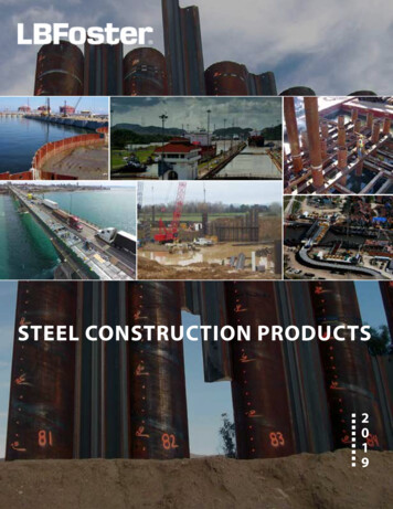
2 Review of existing knowledge2.1Deformations around driven pilesThe pattern of displacements around cylindrical piles driven into relatively uniform clays has beenwell studied, mainly in model tests (for example, Randolph et al., 1979; Francescon, 1983; Gue,1984; Lehane and Gill, 2004) but sometimes in the field (for example, Cooke and Price, 1973;Cooke et al., 1979). Figure 2.1 shows normalised vertical and horizontal displacements from anumber of these studies. Vertical displacement (down-dragging) occurs consistently within aradius (measured before penetration of the pile) of about 1.5 pile diameters. Horizontal outwardmovement extends further and can be predicted relatively simply using undrained cavityexpansion theory (for example, Pestana et al., 2002). Outward radial displacements from thecreation of an infinitely long cylindrical cavity with the same radius as the pile are calculated byassuming that no volume change occurs in the soil. A more comprehensive theory for predictingdeformations exists, known as the ‘strain path method’ (Baligh, 1985; Sagaseta and Whittle,2001), but it does not always perform well for vertical displacements near the pile. In the strainpath method, the soil is assumed to flow around the penetrating pile in the same way that a fluidwith no viscosity would flow.Displacements in layered soils have been studied much less frequently. Moseley (1997)conducted model tests in clay with thin layers of silt or sand and recorded vertical movementswhich were essentially the same as those for homogeneous clay. An average curve based onseveral tests by Moseley is shown in Figure 2.1a. Van den Berg (1994) tested two-layer modelscomprising sand and clay using a penetrometer with a conical tip. He showed that overlyingsand could be pushed down into a weaker clay layer to a depth of about three ‘pile’ diametersregularly, and more than this irregularly. Deformations within the sand layers extended furtherfrom the penetrometer than those in the clay, especially below the penetrometer tip. Verticaldisplacements in the sand extended to a radial distance of around 2.5 ‘pile’ diameters, ascompared with 1.5 ‘pile’ diameters in the clay (consistent with Figure 2.1a). In the field, verticaldisplacements of soil layers have sometimes been observed when excavations have taken placeadjacent to driven piles. These observations are reviewed in Section 5 but the amount of reliablequantitative information from the field is limited.Houlsby et al. (1988) observed failure mechanisms of driven piles in models of carbonate sandscontaining cemented layers. While brittle mechanisms similar to punching shear failuredeveloped in strong cemented layers at low stress levels, entirely ductile failures were observedin weak layers at high stress levels. However, displacements were not reported in detail.Detailed displacements in homogeneous sands have recently been measured by White andBolton (2004). This research, conducted using plane strain models, has revealed a complexpattern of behaviour with significant crushing of sand particles beneath the pile. Verticaldisplacements visibly extended much further from the pile than indicated in Figure 2.1a, roughlyup to a radius of four pile diameters, although the displacements would not have extended as farif the tests had been axially symmetric.2.2Deformations around CFA pilesDuring the boring operation for a CFA pile, the displacements of the surrounding ground aregoverned by the speed of rotation of the auger relative to the speed of vertical penetration (forexample, Vigiani, 1998). Theoretically, it is possible to adjust the speeds so that the volume ofsoil removed is equal to the volume of concrete placed. If this is achieved, displacements of thesurrounding ground should be negligible. However, this relies critically on good control andScience Report SC020074/SR Piling in layered ground: risks to groundwater and archaeology9
workmanship. If the auger is over- or under-rotated, soil will be displaced either towards the pileor away from it. There have been instances of severe ground loss due to over-rotation and therisk is larger in soil deposits containing erodable silt or sand layers below the water table (forexample, Thorburn et al., 1998). Generally, though, the risks are understood and controlled.024681012Vertical displacement / pileradius0.20-0.2Francescon-0.4Cooke et al.-0.6GueLehane and Gill-0.8Moseley-1Initial radius / pile radius(a)Radial displacement / pileradius0.8Francescon0.6Cooke and PriceGue0.4Lehane and GillRandolph et al.0.20024681012Initial radius / pile radius(b)Figure 2.1. Displacements adjacent to driven piles in clay: (a) vertical and (b) horizontal(after Lehane and Gill, 2004)Science Report SC020074/SR Piling in layered ground: risks to groundwater and archaeology10
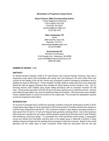
2.3Flow adjacent to driven pilesThe effect of driving piles through a clay aquitard would be extremely hard to isolate and quantifyreliably in the field and it is not surprising that no such field data are available. Furthermore, onlythree previous model studies of this effect have been found in the literature. Figure 2.2 showsthe test cell employed by Hayman et al. (1993). The upper sand layer was saturated withcontaminants (a mixture of two DNAPLs) while the lower sand was saturated with clean water. A12.7 mm diameter cylindrical steel pile was then driven through the soil into the lower sand. Thefluid in the lower sand was flushed out at intervals and its composition monitored. It wasconcluded that no leakage of contaminant along the pile-clay interface took place. However,some contaminant reached the lower sand initially as it was driven down in soil trapped beneaththe pile tip. A similar test was conducted on a wooden pile in which wicking resulted in somedownward migration of contaminant through the pile.Figure 2.2. Test configuration used by Hayman et al. (1993) (after Hayman et al. 1993)Science Report SC020074/SR Piling in layered ground: risks to groundwater and archaeology11
Boutwell et al. (2000) carried out similar tests on a wider range of pile types, including a steel Hsection pile. Brine was used as a contaminant and permeability was measured by applying ahead difference between the upper and lower sands. The earlier results of Hayman et al. wereconfirmed but a preferential flow path was created through the clay by driving the H-section pile.This was attributed to a reduction in lateral pressure on the sides of the pile as compared with asolid cylindrical pile. Further tests of the same type, and similar conclusions, were reported byAchleitner et al. (2004).It has been contended that pile driving in normally consolidated clay soils can cause hydraulicfractures or cracks to form in a plastic zone next to the pile (Massarch and Broms, 1977). Suchcracks are predicted to be radially orientated in vertical planes and have been reportedlyobserved around driven sand drains in Sweden (Massarch, 1978). If present, they would clearlyprovide preferential flow paths. However, there was no evidence of hydraulic fracturing in themodel tests mentioned above or in model tests of driven vertical drains reported by Hird andMoseley (2000), some of which were conducted in normally consolidated clay.2.4OverviewThere are considerable gaps in our knowledge of deformations around piles in the ground,especially for driven piles in layered ground where there is some evidence that the deformationsdepend on the relative shear strengths of the layers. The deformation behaviour and shearstrength of coarse-grained soil will depend on the effective stress level (which is a function ofdepth) and on the density. The degree of soil saturation might also have some influence and, forcertain coarse-grained soils, deformations could depend on the extent of particle breakage orcrushing.There is an even greater lack of published information on the effect of constructing piles throughclay layers acting as aquitards. Very limited research suggests that, for driven piles, solidcylindrical piles have a greater ability than H-section piles to form a seal and prevent increases ofgroundwater flow next to the pile. However, the reason for this has not been clearly establishedand several potentially influential parameters remain to be investigated, including the thickness ofthe clay layer relative to the pile diameter or width. There appears to be no previousexperimental evidence on the sealing abilities of CFA piles.Science Report SC020074/SR Piling in layered ground: risks to groundwater and archaeology12
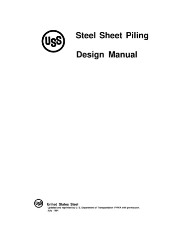
3 Physical modelling methods3.1Axisymmetric modelsAn axisymmetric model, in which a model pile is surrounded by a cylindrical soil body, is thenatural choice for investigating the behaviour of cylindrical piles in the laboratory. However, thelimitations of such modelling include the difficulty of recording displacements within the soilresulting from pile formation and the effect of the finite volume of soil, or boundary conditions. Inthis project, deformations were investigated by dissecting the models after testing. It wasimpractical to construct a model large enough to eliminate boundary effects; for dense coarsegrained materials the diameter of a rigidly contained model would have to be of the order of 60times that of the pile (for example, Ahmadi and Robertson, 2004). Instead, it was intended thattests would be carried out with both rigid and flexible lateral boundaries in order to bracket thebehaviour that would be observed in an infinite soil mass.Models were designed at a nominal geometrical scale of 1:10 and were subjected to a verticalstress equivalent to between about five and ten metres of overburden, depending on theassumed groundwater conditions.However, the tests can be interpreted for a variety ofassumed model scales (for example, by expressing results in a dimensionless form).3.1.1 EquipmentFigure 3.1 gives a schematic diagram of the axisymmetric model test configuration. While thisshows similarities to the tests conducted by Boutwell et al. (2000) and Hayman et al. (1993)(Section 2.3), there are important differences. These include provision to control the lateralpressure acting on the soil, within certain limits, by containing the soil within a membrane andapplication of a back-pressure (elevated pore water pressure) to ensure full saturation of themodel.Three cell bodies of 250mm internal diameter with different heights were designed toaccommodate soil models with different clay layer thicknesses. Each cell could be mounted in aframe equipped with a hydraulic driving system so that a pile could be driven into the soil throughan access hole, (see Figure 3.2a). CFA piles were constructed by mounting a motor on thehydraulic ram to provide rotation of the auger during vertical penetration. Figure 3.2b shows apile being driven into a model, while Figure 3.3 shows the augering equipment.Two straight-sided model piles were made: a 25 mm circular stainless steel pile and an H-sectionaluminium alloy pile with 26mm wide flanges and a 26 mm deep web. With the H-section piles, itis no longer strictly correct to refer to the tests as axisymmetric, but this will be overlooked for thepurposes of this report. A 25 mm diameter stainless steel auger with a hollow 12 mm diameterstem and a pitch of 14mm was also made. The internal diameter of the stem was about 8 mmand a sacrificial plug, which could be blown off by internal pressure, was placed at the base ofthe auger.Science Report SC020074/SR Piling in layered ground: risks to groundwater and archaeology13
RemovablePlugFlow inFlow inPerspex spacerRubber membraneUpperSANDLateral pressure portKaolinCLAYPileStainless steel cell wallLowerSANDPorous plastic packingPerspex spacerRubber membraneVertical pressureportFlow outFigure 3.1. Schematic diagram of axisymmetric test configurationScience Report SC020074/SR Piling in layered ground: risks to groundwater and archaeology14
Hydraulic ramPile3 way operation switchPivot pointsDrive and pull velocitycontrolsTest CellHydraulic pumpTest frame(a)(b)Figure 3.2. Model pile driving equipment: (a) schematic diagram and (b) photographScience Report SC020074/SR Piling in layered ground: risks to groundwater and archaeology15
Ram – auger connectorAuger rotationmotorRotation drivebeltGrout storage chamberBearing housingWiring for motorAugerFigure 3.3. Model CFA piling equipmentTwo systems for measuring permeability were created: a low flow rate system utilising aGeotechnical Digital Systems (GDS) flow pump and a high flow rate system utilising a headertank mounted on vertical racking on the adjacent laboratory wall. The layout of these systems isshown in Figure 3.4.Finally, a pair of 250 mm diameter preconsolidation cells were used to consolidate clay layerswith a known stress history prior to being incorporated in a model.Science Report SC020074/SR Piling in layered ground: risks to groundwater and archaeology16
Back pressureReversible volumechange unitVertical cell pressureTRVAir pressure supply(0 - 7Bar)RVGDSunitHigh A/WinterfaceMODELDTA/WcylinderTAir pressure supply(0 - 7Bar)Lateral cell pressureTAir pressure supply(0 - 7Bar)Reversible volumechange unitA/WcylinderLow A/WinterfaceRV:A/W:DT:T::Pressure reducing valveAir/waterDifferential pressure transducerOrdinary pressure transducerOrdinary valveNote: pore pressure measurement system not shown.Figure 3.4. Hydraulic circuits for permeability testing3.1.2 Test procedureThe soil model was created with the model container (or test cell) inverted so that the upper sandlayer (Figure 3.1) was placed first, followed by the clay layer and then the lower sand layer. Thesands used were coarse and medium quartz sands known as Leighton Buzzard Sand, FractionsB and C respectively (see Figure 4.14 for grading curves). A cylindrical membrane was fitted tothe cell and kept in contact with the cell walls by applying a vacuum. The upper sand wasdeposited through water in the cell and compacted in three layers using a vibrating hammer. Alayer of kaolin clay, preconsolidated from a slurry under a vertical stress of 200 kPa, wasextruded from the preconsolidation cell, cut off with a wire and transferred to the model containerusing a suction pad to minimise dist
The models confirmed that well-constructed CFA piles cause much smaller deformations of the surrounding soil than driven piles. In the models, solid cylindrical piles effectively sealed when driven through a clay layer with a thickness of 2 or more pile diameters. In the field, this sealing ability would preserve the integrity of such a layer