Transcription
RV-10 Pilot’sOperatingHandbookN102FMThe Flying Monkey
Table of ContentsGeneral . Section 1Limitations . Section 2Emergency Procedures . Section 3Normal Procedures . Section 4Performance . Section 5Weight and Balance/Equipment List . Section 6Systems Descriptions . Section 7Handling, Service and Maintenance . Section 8Supplements . Section 9Section 1
GeneralThe RV-10 is a four-place all aluminum aircraft powered by a Lycoming IO-540 6 cylinder fuelinjected engine. With a compression ratio of 8.5:1 it produces approximately 260 hp. Pairedwith a Hartzell two blade constant speed propeller, the aircraft has excellent climb capability andcruises in the range of 160-175 KIAS. With 60 gallons of useable fuel the RV-10 is a competentcrosscountrymachineallowing7-800 milelegs.Exterior DimensionsSpan31 ft 9in.Length24 ft 5 in.Height8 ft 8 inWing Area148 sq ftWeightsEmpty Weight1650 lbsGross Weight2700 lbsLoadingsWing Loading18.6 lb/sq ftPower Loading13.5 - 10.4 lb/hpPowerplant/SystemsEngine260 hpPropellerHartzell C/SFuel Capacity60 US galOtherBaggage100 lbs
GENERAL AIRSPEED TERMINOLOGYKIASKnots Indicated Airspeed is the speed shown on the airspeed indicator assumingno instrument error, expressed in knots.KCASKnots Calibrated Airspeed is indicated airspeed corrected for position andinstrument error, expressed in knots. Calibrated airspeed is equal to true airspeedin standard atmosphereat sea level.KTASKnots True Airspeed is the airspeed relative to undisturbed air, expressed inknots, which is KCAS corrected for altitude, temperature and compressibility.GSGround Speed is the speed of the aircraft relative to the ground.VAManeuvering Speed is the maximum speed at which abrupt full controldeflection will not overstress the aircraft.VFEMaximum Flap Extension Speed is the highest speed permissible with wingflaps in a prescribed extended position.VNOMaximum Structural Cruising Speed is the speed that should not be exceededexcept in smooth air, and then only with caution.VNENever Exceed Speed is the speed limit that may not be exceeded at any time.VSStalling Speed is the minimum steady flight speed at which the aircraft iscontrollable in a specified configuration.VS0Stalling Speed in the landing configuration at the most forward centre of gravity.VXBest Angle of Climb Speed is the speed which results in the greatest altitude gainin a given horizontal distance.VYBest Rate of Climb Speed is the speed which results in the greatest altitude gainin a given time.WEIGHT AND BALANCE TERMINOLOGYReference DatumReference Datum is an imaginary vertical plane from which all horizontaldistances are measured for balance purposes.StationStation is a location along fuselage given in terms of distance from thereference datum.ArmArm is the horizontal distance from the reference datum to the centre ofgravity of an item.MomentMoment is the product of weight of an item multiplied by its arm.(Moment divided by the constant 1000 is used in this handbook tosimplify balance calculations by reducing the number of digits.)
CGCentre of Gravity is the point at which an aircraft, or item, would balanceif suspended.CG ArmCentre of Gravity Arm is the am obtained by adding the aircraft individualmoments and dividing the sum by the total weight.CG LimitsCentre of Gravity Limits are the extreme centre of gravity locations withinwhich the aircraft must be operated at a given weight.Empty WeightEmpty Weight is the weight of aircraft including unusable fuel and fullengine oil.Useful LoadUseful Load is the difference between takeoff weight and empty weight.PayloadPayload is the weight of occupants, cargo, and baggage.Gross WeightGross Weight is the loaded weight of the aircraft.Max T/O WeightMaximum Takeoff Weight is the maximum weight approved for start ofthe takeoff run.Maximum Landing Weight Maximum Landing Weight is the maximum weight approved forthe landing touchdown.NOTES, CAUTIONS AND WARNINGSSpecific items requiring emphasis are expanded upon and ranked in increasing order ofimportance in the form of a NOTE, CAUTION or WARNING.NOTEExpands on information which is considered essential to emphasize. Information contained innotes may also be safety related.CAUTIONProvides information that may result in damage to equipment if not followed.WARNINGGEmphasizes information that may result in personal injury or loss of life if not followed.
ABBREVIATIONSTo be added
Section 2LimitationsAIRSPEED INDICATOR MARKINGSMARKINGKIASSIGNIFICANCEBottom of White ArcVSO52Full Flap Stall SpeedTop of White ArcVFE87Max Flax Extension SpeedBottom of Green ArcVS61No Flap Stall SpeedBlue LineVA125Maneuvering Speed156-200Caution Range200 KTASNever Exceed SpeedYellow ArcRed Line*VNEGAUGE MARKINGS/OPERATING LIMITATIONS/ALERT LOGICIndicatorOut of Range Caution LowLowNormalCaution High Warning HighNotesRangealarms only set where notedManifoldPressureRPMOil PressureOilTemperatureFuel Pressure10-30 5000-25 12Fuel FlowCHTEGT500 - 2700 270025-5555-9595-115 115120-165165-220220-245 24512-1414-450-11-27150-250250-400400-435435-500 10001000-15001500-1550 155010-11.5V11.5-12.5 (White)12.5-14.8 (Green)0-55-300-55-30 27white lines at 2350 and 2450; alert hi (red)Indication w/in 30 sec of startwhite line at 200 for eng life at cruisemight set wh lines for cruise (13, 11.5, 10.5,8.7) FOR 75, 65, 60 AND 50 percent HPAmps(Main Bus)Volts(Battery)Fuel Q1 (L)Fuel Q2 (R)No markings, 0-60A 10 V 14.8 VAlert at Caution Low ( 11.5V)Alert low ( 5 gal) white line at 10/20 galAlert low ( 5 gal) white line at 10/20 gal
STARTER LIMITS5-8 seconds cranking per start attempt30-40 seconds between start attemptsMaximum 5 start attempts, the 30 minute cool downAlso of note, both magnetos are impulse coupled and therefore capable of starting the engineindividually; normal starting procedure is to use both magnetos.WEIGHT LIMITSMaximum Weight . 2700 lbsEmpty Weight . 1650 lbsUseful Load . 1050 lbsBaggage Compartment. 100 lbsFor CG and loading examples see Section 6LOAD FACTOR LIMITS 3.8/-1.5 g’sOPERATIONS LIMITSThe aircraft is approved and equipped for Day/Night VFR/IFR operations. Flight into known orforecast icing or in the vicinity of thunderstorms is prohibited.PLACARDS
Section 3Emergency ProceduresEMERGENCY CHECKLISTFIRE DURING START1. Cranking . CONTINUE2. Throttle. FULL OPEN3. Mixture. CUTOFF4. Fuel Selector . OFF5. Battery/Alt Switch . OFF6. Fire Extinguisher . GRAB7. Egress Aircraft8. Extinguish Fire or Clear AreaENG FAIL DURING TAKEOFF1. Throttle. IDLE2. Brakes . AS REQ’D3. If Departing Prepared Surfacea. Mixture . CUTOFFb. Battery/Alt Switch . OFFc. Magnetos. OFFd. Fuel Selector . OFFENG FAIL IMM AFTER TO1. Glide. ESTABLISH2. Landing Site . SELECT3. Mixture. CUTOFF4. Fuel Selector . OFF5. Battery/Alt Switch . OFFENG FAIL IN FLIGHT1. Glide. ESTABLISH2. Landing Site . SELECT3. Restart . ATTEMPT. (if warranted)4. Mixture. CUTOFF5. Fuel Selector . OFF6. Flaps . EXTEND7. Battery/Alt Switch . OFFENG RESTART IN FLIGHT1. Throttle. ¼ OPEN2.3.4.5.6.Prop . FULL FWDMixture. RICHBoost Pump .ONFuel Selector .SWITCH TANKSMagnetos . BOTH ONENG FIRE IN FLIGHT1. Mixture. CUTOFF2. Fuel Selector . OFF3. Boost Pump . OFF4. Cabin Heat/Fwd Vents . OFF5. Forced Landing . EXECUTEFORCED LANDING1. Airspeed . 85 KIAS2. Mixture. CUTOFF3. Fuel Selector . OFF4. Flaps . EXTEND5. Battery/Alt Switch . OFF6. Flaps . AS REQ’D7. Fly All the Way Into Crash, Attempt toTouchdown at Minimum SpeedROUGH ENGINE OR LOSS OFPOWER1. If sudden and severe:a. Check Mags One at a Time2. Throttle. ADJUST3. Mixture. ADJUST4. Boost Pump .ON5. Fuel Selector .SWITCH TANKS6. If Plug Fouling Suspecteda. Lean Engine7. If Intake Blockage Suspecteda. ALT AIR Door . OPENLOW OIL PRESSURE1. Power . REDUCE2. Eng Failure May be Imminent
a. Use power while available tomaneuver within gliding distanceof landing siteb. Maintain glide profile3. If Engine Failsa. Glide. Establishb. Mixture. CUTOFFc. Fuel Selector . OFFd. Flaps . EXTENDe. Battery/Alt Switch . OFFHIGH OIL TEMP1. Oil Cooler Door . PUSH IN2. Power Demand . REDUCE3. Airspeed . INCREASE4. If Oil Temp Remains High:a. Land As Soon As ConditionsPermitELECTRICAL FIRE1. Battery/Alt Switch . OFF2. IBBS Switch. OFF3. Overhead Vents . OPEN4. Fire Extinguisher . USE If Req’d5. Land As Soon As Conditions PermitALTERNATOR FAILURE1. Batt/Alt Sw BATT, then BATT/ALT2. If Reset Attempt Fails:a. BATT/Alt Sw . BATTb. Voltage . CHECK3. If Less than 11.5 Voltsa. ESS BUS Switch .ONb. Batt/Alt Switch. OFFc. B/U Switches ON, As Req’d4. If Req’d Prior to Landinga. Batt/Alt Switch. BATTAUTOPILOT MALF1. AP Disconnect . DEPRESS2. AP Panel Buttons . OFF3. Speed/Bank .AS REQ”D4. To Remove Electrical Power:a. Batt/Alt Switch. OFFb. ESS BUS Switch .ONc. ESS BUS Items . AS REQ’D5. If Trim Necessarya. ESS BUS Trim Switch .B/Ub. Use UP/DOWN Panel SwitchRUNAWAY TRIM1. Maintain Aircraft Control2. Use Bank to Control Pitch Up3. Trim Switch on ESS BUS . OFF4. Adjust Speed for Trim ConditionCO MONITOR ALARM1. If Oxygen Available . DON2. Cabin Heat/FWD Vents . OFF3. Overhead Vents . OPEN4. Land As Soon As Conditions PermitSTATIC SOURCE BLOCKAGE1. Alt Static Switch .ALT2. Apply Corrections3. Crosscheck with GPSSPINS1. Throttle. IDLE2. Rudder . OPPOSITE SPIN/BALL3. Stick . FWD TO BREAK STALL4. RECOVER FROM DIVEDOOR DEPARTURE1. Speed . REDUCE2. Rudder . INTO OPEN DOOR3. Loose Items . STOW4. Elevator . CHECK VISUALLY5. Land as Soon as Conditions PermitDITCHING1. Radio. TRANSMIT MAYDAY2. Flaps . FULL3. Airspeed . 70 KIAS4. Descend . 300 FPM5. Approach .a. High Wind . INTOb. Light Wind . ParallelTo Swells6. Seat/Shoutlder Harnesses . TIGHTEN7. Doors . UNLATCH8. Evacuate After TouchdownICING1. Turn Back or Change Altitude2. Throttle. OPEN3. Pitot Heat .ON4. ALT AIR Door .OPEN, if Req’d
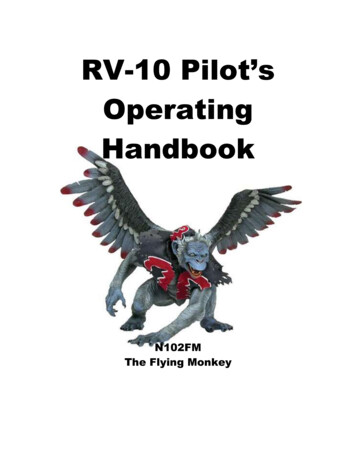
5. Landing . Increase Speeda. Consider No-FlapsAMPLIFIED EMERGENCY PROCEDURESENGINE FIRE DURING STARTThe most important consideration with a fire indication on the ground is personal safety. Youare sitting on 60 gallons of 100LL, so time spent attempting to reduce or eliminate the fireincreases the risk of injury. Continuing to crank while securing the engine should assist incontaining the flames and reducing the source of the fire, but egressing should follow shortly.Likewise, the fire extinguisher is not likely to be of assistance from inside the cockpit. Time andconditions permitting, grabbing it on the way out may provide a chance to reduce damage or putout the fire, depending on the situation.ENGINE FAILURE DURING TAKEOFFAny indication that the engine is not performing correctly should result in aborting the takeoff;the earlier the decision is made the better. The brakes provide excellent stopping power, whichmay be increased slightly with increasing back pressure as the airspeed decreases, and byretracting the flaps if down. If runway departure appears likely, attempt to secure the engineonly if able to continue maintaining aircraft control.If engine failure occurs without sufficient runway remaining, it is critical to attain/maintain glidespeed while selecting the least crummy area to land in. It is not recommended to attempt anysignificant turning, other than to avoid obstacles, unless the aircraft has reached approximately1,000 AGL minimum. The pitch change from climb out to glide speed will be significantespecially considering reaction time. Lowering flaps to full will significantly reduce thetouchdown speed.ENGINE FAILURE DURING FLIGHTEstablishing glide speed and aiming towards a suitable landing area are the critical items toaccomplish in the event of an engine failure - time should not be spent on failure analysis orengine restart attempts before these steps are accomplished. Pilots should also select a minimumaltitude below which restarting will not be attempted at all because the focus will need to be onpreparing to land. Pulling the propeller control full aft may slightly increase glide performance ifthere is sufficient oil pressure remaining. No wind the RV-10 glides approximately 1.4 NM per1,000 ft altitude at a best glide speed of 85 KIAS, based on flight testing with engine at idle, propfull forward.The engine restart procedure is to place the throttle in the normal starting position, mixture torich, turn the boost pump on and switch tanks (provided it has fuel). This should result in fuelflow/fuel pressure indications. One other consideration is to open the alternate air door if anintake blockage is considered possible. After the engine has restarted, careful consideration
should be given to turning off the boost pump or closing the alternate air door if opened, as thiscould lead to another failure. Land as soon as conditions permit.Glide Distance25242322212019181716Distance, 8Altitude in 1,000'sOIL SYSTEM MALFUNCTIONSLow oil pressure may be the result of low oil quantity or indicate a possible leak, especially withincreasing oil temperature. In either case land as soon as possible because engine failure may beimminent. Because of this it is recommended to intercept an engine out glide profile to the
intended landing site. High oil temperature by itself may result from the oil cooler damper beingclosed or a blockage of the oil cooler. Temperature that does not start coming back down aftertaking corrective actions may also indicate impending engine failure, therefore the landingrecommendations are the same.ELECTRICAL MALFUNCTIONSAn understanding of the electrical system helps explain the procedures in the event of amalfunction. Most electrical items are powered through the Vertical Power VPX, which is itselfpowered via the BATT/ALT switch. With this switch in the BATT position, the 28AH aircraftbattery is the sole source of power. Under a normal load (all avionics on, strobes on, landing/taxiand nav lights off, pitot heat off) battery power should last for 90 minutes or more, depending onthe state of the battery. During flight testing the battery lasted almost two hours, with systemsstarting to degrade about 15 minutes before that. The checklist recommends switching theBATT/ALT switch off at 11.5 volts as this is the point at which there is approximately 30minutes of battery power left. If not needed to extend the IBBS ‘life’ of the G3X, it can beturned off sooner; if turned off later, there will be less power left available, to the point at whichthe battery contactor will not close.With the BATT/ALT switch in the off position, the Dynon D-6 will continue to function on itsown internal backup battery for over two hours. Additionally, the two left screens of the G3Xwill last approximately two hours utilizing the Internal Battery Backup System, or IBBS. Enginemonitor functions will be degraded or lost, and the GPS will revert to the internal G3X as theGTN 650 does not have backup power.The ESS BUS is designed to power the GRT 200, audio panel, transponder and pitch trim asneeded in the event the BATT/ALT switch is placed off (or the VPX fails), and to extend theamount of time the G3X remains operational. By turning the red covered ESS BUS switch on,power is made available directly from the battery.Selecting the B/U position of the COMM 2/AUDIO, XPDR, or PITCH TRIM switches connectsthat power to the item. Likewise, returning the switch(es) to the OFF position removes power ifnot needed or to conserve power until needed again. The pitch trim in the B/U mode is activatedby the toggle switch next to it, not via the coolie hats on the control sticks. As an aside, innormal flight operations these switches provide a means to turn these items off, which may bevaluable particularly in a trim malfunction situation. Finally, the IBBS switch next to the ESSBUS switch provides power from the battery through the IBBS to power the G3X. This extendsthe amount of time available to the G3X beyond the internal IBBS battery by the amount ofenergy left in the ships battery, if desired.
If operating with the BATT/ALT switch off, no other systems will be available, to include alllights, flaps and pitot heat. Depending on the time elapsed from turning off the BATT/ALTswitch to point of intended landing, the state of the battery, and conservative use of availablesystems, the BATT/ALT switch can be placed back in the BATT position for power to lowerflaps, turn on exterior lights or other functions.Under normal operations, all systems receive power via the VPX, which has its own page on theG3X MFD, which can be used to see tripped electronic circuit breakers, overcurrent trips, or theactual component current draw. Most of these individual circuit faults are resettable via the VPXscreen.FORCED LANDINGBest Glide speed is 85 KIAS; glide range may be increased slightly with the propeller controlpulled aft if there is sufficient oil pressure to move the blades. The minimum altitude over therunway for a high key position is 1,000’ AGL, and 500’ AGL can be used for a low key abeam
the touchdown point. Consider the wind when determining glide range and landing direction.Flaps should be extended to full once the landing is assured.ROUGH RUNNING ENGINEThis checklist is designed to address fuel, mixture, ignition and air source problems. If theroughnes is sudden and severe, not following any pilot input, it could be due to a magneto gearfailure/partial failure. In this case immediate action is recommended, switching the magenetosoff one at a time. If the engine recovers somewhat, leave the affected magneto off and land assoon as conditions permit.
Section 4Normal ProceduresAIRSPEEDS FOR NORMAL OPERATIONSSpeedDescriptionKIASVRRotation Speed60-70VXBest Angle Climb Speed78VYBest Rate Climb Speed90Cruise Climb Recommended Climb Speed120-130VBGBest Glide Speed85VSOStall Speed, Full Flaps50VS1/2Stall Speed, ½ Flaps53VSStall Speed, Flaps UP65VFEMax Flap Extension Speed, ½ to Full87VFE1/2Max Flap Extension Speed, Up to ½96VFE1/4Max Flap Extension Up to 0 (Reflex to 120zero degreesVREFFinal Approach Speed, Full Flaps70VREF0Final Approach Speed, 0 Flaps80HoldingRecommended120Inst FinalRecommended80Notes:-Stall speeds based on Max Gross Weight flight testingCruise climb recommended thru 5,000 feet for cooling and fuel efficiency120 KIAS is recommended for instrument holding/maneuvering, such as radar pattern80 KIAS instrument final is based on full or half flap configurationVNE is 200 KTAS vs indicated; the G3X displays VNE at the calculated KIAS
Normal ProceduresBefore Exterior Inspection1. Flaps . DOWN2. Batt/Mag Switches . OFF3. Gust Lock .REMOVED4. Covers .REMOVEDExterior Inspection1. Baggage Door . CLSD/LOCKED2. Antennae . CONDITION3. Static Port . CHECK4. NACA Vent . CHECK5. Fairings . CHECK6. Elevator . CHECK7. Trim Tabs . CHECK8. Rudder Cable . CHECK9. Rudder . CHECK10. Access Panels . CHECK11. Static Port . CHECK12. NACA Vent . CHECK13. Step . CHECK14. Flap . CHECK15. Aileron . CHECK16. Fairing/Lights . CHECK17. Fuel/Cap . CHECK18. Fuel Sample . CHECK19. Fuel Vent . CHECK20. Main Wheel/Fairings . CHECK21. Nose wheel/Fairings. CHECK22. Cowl/exhaust. CHECK23. Intakes . CHECK24. Propeller . CHECK25. Oil Level . CHECKa. 6-8 quarts is normal26. Oil Door . CLOSED27. Main Wheel/Fairings . CHECK28. Fuel Vent . CHECK29. Fuel Sample . CHECK30. Fuel/Cap . CHECK31. Pitot Tube . CHECK32. Fairings/Lights . CHECK33. Aileron . CHECK34. Flap . CHECK35. Windows . CLEAN/AS REQD36. Chocks.REMOVEDBefore Start1. Strap In . COMPLETE2. Passengers . CHECK3. Dynon . . .ON4. IBBS Switch. . .ON5. Battery Switch . . .ON6. Ext lights . AS REQ’D7. Essential Bus Switch . CLOSEDSwitches . NORM8. Flaps . UP9. Alt Air . IN10. Alt Static . NORM11. Audio panel . SET12. Radio . AS REQ’D13. A/P . DISCONNECT14. EFIS boot up . COMPLETE15. Oil Damper. AS REQ’D16. Fuel Selector . L OR R17. Flight Controls . CHECKED18. Doors . CHECKEDStarting Engine1. Prop .FULL FWD (fine)2. Prime, if requireda. Throttle 1/8 openi. Note that is not 1/8 inch b. Boost Pump .ONc. Mixture . RICHd. Boost Pump . OFF3. Throttle. ¼ INCH OPEN4. Prop . FWD5. Mixture.FULL LEAN6. Right Mag Sw . OFF or ON7. Left Mag. START, THEN ONa. Mixture . FULL RICHb. Throttle . IDLE8. Right Mag .ON9. Oil Pressure . IND10. If starting hot engine:a. RPM . 1200-1500b. Boost pump .ONBefore Taxi1. Mixture. LEAN for GND OPS2. Alternator .ON
3. Flaps . UP4. Radios . SET5. Flight Plan . SET6. Safe Taxi or Airfield7. Transponder . SET AND ON8. Altimeter . SET9. External Lights . AS REQ’D10. Heading . CHECK11. Dynon . OPERATIONAL12. Mixture. CHECK2.3.4.5.6.Climb1. Throttle. SET MP2. Prop . AS REQ’D3. Speed . 120 for now4. Mixture. AS REQ’D5. Eng Instruments . CHECKAuto Pilot1. AutoPilot . ENGAGE2. Flight Controls . CHECK3. AP DISC .PRESS4. Flight Controls . Check5. Trim.Set TakeoffTaxi1. Brakes . CHECK2. Instruments . CHECKa. Turn/Slipb. Headingc. VOR/ILS (ground checkavailable)d. RAIM3. Set Mode and scale4. Voltage . CHECKBefore Takeoff1. Mixture. RICH2. Throttle. 50%3. Mags . CHECK4. PropCHECK, set fine pitch5. Throttle. IDLE6. MixtureLEAN if DA above 5,000 ft7. Boost Pump . On8. Trim. SET FOR TAKEOFF9. Doors LATCHED AND CHECKED10. Seat belts . FASTENED11. Exterior lights. AS REQ’D12. Interior lights . AS DESIRED13. Pitot Heat . AS REQ’D14. Transponder .CHECK/SET15. Departure. BRIEFTakeoff1. Throttle. MAXEng Instruments . CHECK50-60 KIAS .ROTATEFlaps . UPBoost Pump . OFFCHT. MonitorLevel Off1. Throttle. Set MP2. Prop . AS REQ’D3. Mixture. AS REQ’D4. Eng Instruments . CHECK5. Fuel . CHECK6. Altimeter . SETifCruise1. Flight Log.UPDATE2. Fuel . CHECK3. Eng Inst . CHECK4. Oil Temp . CHECKDescent1. Throttle. AS REQ’D2. Prop . AS REQ’D3. Mixture. RICH, AS REQ’D4. Altimeter . SET5. Fuel . CHECK6. Pitot Heat . AS REQ’D7. Exterior Lights . AS REQ’D8. Approach .IF REQUIRED9. FBO . CONTACTBefore Landing1. Throttle. AS REQ’D2. Prop . FINE3. Mixture. RICH4. Boost pump .ON5. Speed . COMPUTE6. Lights . AS REQ’DAfter Landing1. Brakes . AS REQ’D
2.3.4.5.6.Flaps . AS REQ’DExterior Lights . AS REQ’DPitot Heat . OFFBoost pump . LEAVE ON high TMixture. LEAN for GND OPSShutdown/Secure1. Flaps . DOWN2. Trim. T/O3. Boost pump . OFF4. Mixture. FULL LEAN5. Throttle. OFF6. Magnetos . OFF7. Battery . OFF8. IBBS . OFF9. Fuel Selector . OFF
AMPLIFIED PROCEDURESPREFLIGHT INSPECTIONThe preflight is designed to start and finish at the pilot step, progressing in a counter-clockwisedirection around the aircraft. Pay particular attention to flight control hinges/attachment points,threads showing beyond nuts, cotter pins and freedom of movement. All access panels should bevisually checked for security. It is recommended that the flaps be extended both for inspectionand to reduce the chances of a passenger stepping on them.Fuel should be visually checked and ‘dipped’ if necessary to confirm the quantity shown on thegauges. The oil level is more accurately checked before flight then after when the engine is stillwarm. Attempt to maintain the oil level between 6 and 8 quarts; so far oil consumption appearsto be between 5 and 10 hours per quart.Once the preflight is completed, consider checking that the tool kit (including 2 qts of oil), gustlock, tow bar (if req’d), window cleaner, tie down stake kit, and any other travel items necessaryare packed. U
CG Centre of Gravity is the point at which an aircraft, or item, would balance if suspended. CG Arm Centre of Gravity Arm is the am obtained by adding the aircraft individual moments and dividing the sum by the total weight. CG Limits Centre of Gravity Limits are the extreme centre of gravity locations within which the aircraft must be operated at a given weight.