Transcription
How to Configure PowerCenter10.2 HotFix 2 on Kubernetes Copyright Informatica LLC 2019, 2021. Informatica, the Informatica logo, and PowerCenter are trademarks orregistered trademarks of Informatica LLC in the United States and many jurisdictions throughout the world. Acurrent list of Informatica trademarks is available on the web at https://www.informatica.com/trademarks.html
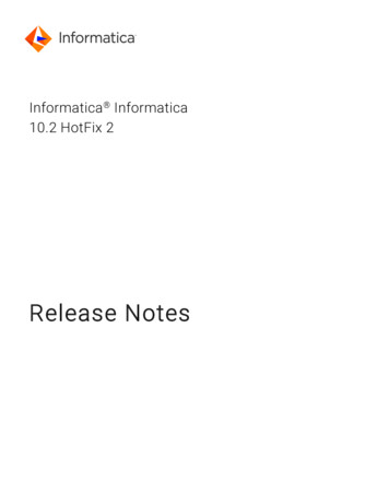
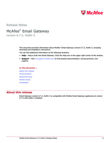
AbstractYou can configure PowerCenter on Kubernetes to optimize resource management and to enable load balancing for theInformatica domain within the containerized environment. This article is written for the PowerCenter administratorresponsible for configuring PowerCenter 10.2 HotFix 2 on Kubernetes.Supported Versions PowerCenter 10.2 HotFix 2Table of ContentsHow PowerCenter Works with Kubernetes. . . . . . . . . . . . . . . . . . . . . . . . . . . . . . . . . . . . . . . . . . . . 2Kubernetes Architecture. . . . . . . . . . . . . . . . . . . . . . . . . . . . . . . . . . . . . . . . . . . . . . . . . . . . . . . . 4Kubernetes Overview. . . . . . . . . . . . . . . . . . . . . . . . . . . . . . . . . . . . . . . . . . . . . . . . . . . . . . . . 4Kubernetes Master Node. . . . . . . . . . . . . . . . . . . . . . . . . . . . . . . . . . . . . . . . . . . . . . . . . . . . . . 4Kubernetes Worker Node. . . . . . . . . . . . . . . . . . . . . . . . . . . . . . . . . . . . . . . . . . . . . . . . . . . . . . 5Components in the Kubernetes Architecture. . . . . . . . . . . . . . . . . . . . . . . . . . . . . . . . . . . . . . . . . 6Advanced Components in the Kubernetes Architecture. . . . . . . . . . . . . . . . . . . . . . . . . . . . . . . . . . 7Configuring PowerCenter on Kubernetes Overview. . . . . . . . . . . . . . . . . . . . . . . . . . . . . . . . . . . . . . . 8Step 1. Complete the Prerequisites. . . . . . . . . . . . . . . . . . . . . . . . . . . . . . . . . . . . . . . . . . . . . . . . . 8Verify Port Requirements. . . . . . . . . . . . . . . . . . . . . . . . . . . . . . . . . . . . . . . . . . . . . . . . . . . . . 9Verify System Requirements. . . . . . . . . . . . . . . . . . . . . . . . . . . . . . . . . . . . . . . . . . . . . . . . . . . 10Step 2. Create a Kubernetes Cluster on Google Cloud Platform. . . . . . . . . . . . . . . . . . . . . . . . . . . . . . 10Step 3. Create a Database with a Persistent Volume. . . . . . . . . . . . . . . . . . . . . . . . . . . . . . . . . . . . . 11Step 4. Create a Network File System. . . . . . . . . . . . . . . . . . . . . . . . . . . . . . . . . . . . . . . . . . . . . . . 11Step 5. Share the License Key for the Nodes on the NFS Mount. . . . . . . . . . . . . . . . . . . . . . . . . . . . . . 12Step 6. Create a Docker Image for PowerCenter. . . . . . . . . . . . . . . . . . . . . . . . . . . . . . . . . . . . . . . . 12Step 7. Create a Secret to Secure the Password and Key Pass Phrase. . . . . . . . . . . . . . . . . . . . . . . . . . 12Step 8. Create a Pod that Runs on the Informatica Services. . . . . . . . . . . . . . . . . . . . . . . . . . . . . . . . . 13Step 9. Expose the Node Ports to Communicate with Informatica Server from Outside the Cluster. . . . . . . . 13Step 10. Connect to the Administrator Tool. . . . . . . . . . . . . . . . . . . . . . . . . . . . . . . . . . . . . . . . . . . 14Step 11. Create a Pod that Runs on Informatica Gateway Node. . . . . . . . . . . . . . . . . . . . . . . . . . . . . . 14Step 12. Expose Node Ports for Informatica Services with Kubernetes Services. . . . . . . . . . . . . . . . . . . . 15Step 13. Connecting to the Domain from the PowerCenter Clients. . . . . . . . . . . . . . . . . . . . . . . . . . . . 15Troubleshooting. . . . . . . . . . . . . . . . . . . . . . . . . . . . . . . . . . . . . . . . . . . . . . . . . . . . . . . . . . . . 16How PowerCenter Works with KubernetesTo create and deploy a self-contained PowerCenter application with a scalable and distributed environment, you canintegrate PowerCenter with Kubernetes.To use PowerCenter with Kubernetes, you can host an NFS server to share a mount across all the nodes and to keepthe license key file available to the Informatica domain. If a database is not available, create a pod to host the2
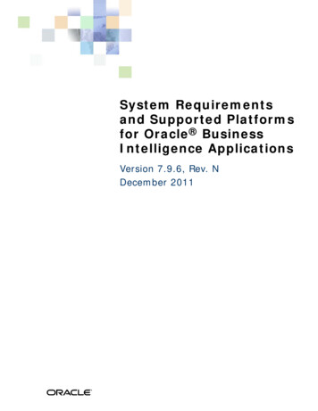
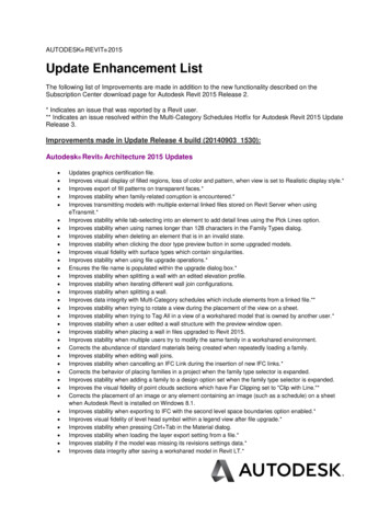
database. Create a pod for PowerCenter master gateway node and deploy the gateway nodes once the mastergateway node is up and running. You can connect through the PowerCenter clients as required when the configurationsetup is complete.The following image displays the PowerCenter on Kubernetes cluster:The diagram shows how a Kubernetes cluster comprises two PowerCenter gateway nodes that shares an NFS mount,which is linked to the Informatica PowerCenter master node. The master gateway node is connected to the repository.The Repository Service can be configured on any of the nodes. The Kubernetes cluster connects to the on-premisesapplications or databases and also connect to the PowerCenter clients.The following image shows the PowerCenter architecture on Kubernetes where the second level view that shows theinternal communication among pods:The diagram shows several pods on separate Kubernetes cluster nodes. Each pod resides within a node. One nodecontains a pod to store the database server and also a database persistent volume. The remaining nodes refer toPowerCenter installation on Kubernetes that exposes the NodePort and helps to interact with the PowerCenter clientswith the internet network. One node connects to the PowerCenter installation on Kubernetes with the exposed portsand contains an NFS server pod and also an NFS based persistent volume.3
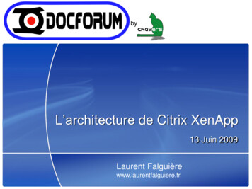
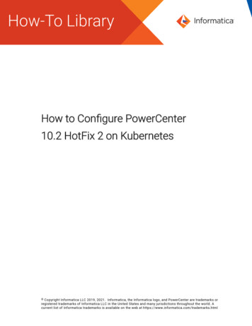
Kubernetes ArchitectureKubernetes (K8s) is an open source system for managing containerized applications across multiple hosts, providingbasic mechanisms for deployment, maintenance, and scaling of applications.Kubernetes architecture comprises of kubectl, which is a command line interface that runs commands against theKubernetes clusters. Kubernetes also has an API server that runs on the master node. ETCD is a distributed key-valuestore. The Kubernetes state is defined in ETCD. It is followed by one or more worker nodes where the workloads run.You can specify declarative artifacts for Kubernetes, which are defined using yaml files and these yaml definitions aresubmitted to the master. Depending on the definition, constraints, and rules, the Kubernetes master node schedulespods or artifacts submitted in one of the nodes. Similar to any distributed computing architecture, the master managesthe front end operations and the nodes come together to form a cluster. The registry, either public or private, cancentrally stores the docker images, such as a docker hub or a Google container registry.Kubernetes OverviewA Kubernetes engine is a cluster comprised of one or more master nodes and multiple worker nodes.A node is a VM hosted on a platform or a server. The node is the component that provides the compute power to theKubernetes cluster. It is also possible to have a single node master and worker setup, where the master and worker arethe same node.The following diagram illustrates the Kubernetes components, such as the Kubernetes master that connects to thedifferent nodes:The diagram shows a Kubernetes engine with six VMs and two clusters. Each cluster contains three VMs. Kubernetesresides on the VMs. You can use Kubernetes to determine the VMs to deploy the PowerCenter containers based onstorage and compute capability.Kubernetes Master NodeThe Kubernetes cluster master runs the Kubernetes control plane processes, including the Kubernetes API server,scheduler, and core resource controllers.The following master components are required on a Kubernetes cluster:kube-apiserverMaster component that exposes the Kubernetes API for all operations.4
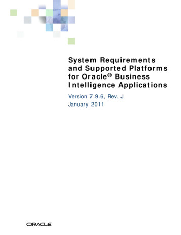
The master is the unified endpoint for the cluster. All interactions with the cluster are done through theKubernetes API calls, and the master runs the Kubernetes API server process to handle those requests. Thecluster master's API server process is the hub of all communication for the cluster. The internal clusterprocesses, such as the cluster nodes, system and components, and application controllers act as clients ofthe API server.kube-schedulerAssigns pods to nodes. It also finds free nodes for any workloads before scheduling workloads to the node.kube-controller-managerManages the cluster and interacts with the various APIs in the kube-apiserver.The following diagram shows the Kubernetes master node components:The diagram shows how all the services run on the Kubernetes master node. The Kubernetes dashboard or client,kubectl interacts with the API server that runs on the master. The API makes specific calls that enables Kubernetes toprocess scheduler and controller manager to perform specific tasks. Other than the API calls, you can alsocommunicate to the Kubernetes master through the Kubernetes CLI command known as kubectl.A scheduler schedules the artifacts such as containers or pods across multiple nodes based on the constraints. Acontroller is responsible for coordination and manages health of the entire cluster, such that the nodes are up andrunning and the pods perform correctly in the desired configuration state. ETCD is similar to a database that storescluster state and configuration data accessed in key value pairs. ETCD can run either on the master or outside thecluster based on the high availability needs.Kubernetes Worker NodeThe worker nodes run the workloads.The worker node contains kubelet and kube-proxy that both connects to the pods within the docker. Informaticaprocesses along with different OS images that runs on the worker node.The following node components are needed on a Kubernetes cluster and can also run on master node:kubeletA kubelet takes information from the master node and ensures that any pods assigned to it are running andconfigured in the desired state. All Kubernetes nodes must have a kubelet. The kubelet creates a pod, makesit container ready, probes, and performs a readiness check.5
kube-proxyWatches on all services and maintains the network configuration across all elements of the cluster.Container runtimeEngine that runs the containers. Containers at runtime such as Docker or RKT are based on the setupconfigured.The following image shows the Kubernetes worker node components:The image shows how the worker node contains the Kubelet and the kube-proxy that is connected to the pods. Thekubelet helps to control the state of the files. The docker image registry stores the images of the Informatica binaries,Redhat operating system, and Microsoft SQL Server database. There are two pods that contain different images. Pod 1contains Informatica domain and services with Red Hat operating system and Pod 2 contains the Microsoft SQL serverdatabase. Both the pods resides in a Docker container runtime that you can run as a docker image or a service regularon a system.Components in the Kubernetes ArchitectureThe following components are integral to the Kubernetes architecture:PodsA group of one or more containers with shared resources and instructions on how to run containers. Podscan communicate within the cluster using the service IP.The following image shows the different pods and the various states in which a pod can exist:Pod 1 contains a containerized application. Pod 2 contains a containerized application and the volume. Pod 3contains two volumes and one containerized application. Pod 4 contains two volumes and threecontainerized applications.6
ServicesAn abstraction that defines a logical set of pods and a policy by which to access the pods. A service inKubernetes is a rest object that is similar to the pod. Kubernetes services support TCP and UDP for protocols,where the default is TCP. Pods are ephemeral but the services are more stable and you can communicatebetween different services. It is the Kubernetes service that routes traffic to the specific pod with the sameapplication label.The following image displays a pod with a service targeting the pod using the application label:The image shows how a pod with a service A targets the pod with the application label as app A.VolumeA directory that contains data that is accessible to the containers in the pod. A volume lasts longer anycontainers that run within the pod and data is preserved across container restarts. It also helps maintain thestate within the cluster.NamespacesSeparates workloads from each other along with the resource constraints on each. For example, the pod orservice can have multiple developers with a namespace for each developer. To provide a similar workload foreach developer, you can configure each namespace state to consume no more than 2 GB RAM.Advanced Components in the Kubernetes ArchitectureThe following advanced components pertain to the Kubernetes architecture:Replica Set or Replication ControllerCreate similar pods in a cluster. Both replica set and controllers allow you to create more pods in a clusterwhen you launch a pod based on availability.DeploymentMost common form of deployment combines replica set and also helps to roll out or roll back images with acontinuous deployment scenario.StatefulSetAllows you to easily run databases or anything that requires some persistent state.DaemonSetEnsure that there is at least one pod running on each node. You can use daemon sets for logging drivers,monitoring agents, or security agents that you want to run across your cluster.7
JobOne or more tasks that you want to run. For example, you have some batch processing jobs to be done andyou want to run it once on that batch. After the jobs complete, the pods get destroyed.Configuring PowerCenter on Kubernetes OverviewYou can configure PowerCenter on Kubernetes to optimize resource management and to enable load balancing for theInformatica domain within the containerized environment.In a multi-node cluster environment, it can be difficult to manage containers that can exist on any of the nodes in acluster. It also becomes tedious to control and manage the creation of newer containers.K8s controls the entire container management and orchestration. With K8s, you can package an application in acontainer image. With K8s, the containers help to decouple the application from the infrastructure. You deploycontainers based on operating-system-level virtualization instead of hardware virtualization. With the applicationcentric management, it raises the level of abstraction from running an operating system on virtual hardware to run anapplication on an operating system using logical resources.The containers are isolated from each other and from the host. The containers have their own file systems and you canbind the computational resource usage. They are easier to build than VMs because the containers are decoupled fromthe underlying infrastructure and from the host filesystem. The containers are portable across clouds and operatingsystem distributions, such as Ubuntu, RHEL, CoreOS, on-prem, and Google Kubernetes Engine.When you run PowerCenter in a containerized environment and configure the Kubernetes setup, it helps to optimize theresource management and provide horizontal scaling of pods based on the load provided on the domain.To run PowerCenter on Kubernetes using Google Cloud Platform (GCP), complete the following steps:1.Complete the prerequisites.2.Create a Kubernetes cluster on GCP.3.Create a database with a persistent volume.4.Create a network file system.5.Share the license key for the nodes on the NFS mount.6.Create a docker image for PowerCenter.7.Create a secret for securing the password and the key pass phrase.8.Create a pod that runs on the Informatica services.9.Expose the node ports to communicate with Informatica server from outside the cluster.10.Connect to the Administrator tool.11.Create a pod that runs on Informatica gateway node.12.Expose node ports for Informatica services with Kubernetes services.13.Connect to the domain from the PowerCenter clients.Step 1. Complete the PrerequisitesBefore you install Kubernetes on Google Cloud Platform (GCP), verify the pre-installation requirements.Ensure that you meet the following installation prerequisites:1.Install the unzip utility to create image with Informatica utility.2.In GCP, specify ingress and egress rules to the firewall of the cluster VMs based on the supported portrequirements. For more information about the supported ports, see Verify Port Requirements.8
For more information about firewalls, see the following GCP documentation r more information about how VMs can communicate with each other, see the following GCPdocumentation network-tags3.Enable RHEL subscription to create RHEL containers.4.Download the files listed in the article from the following Informatica Knowledge Base y/1/1316-PConKubernetes.zipYou also need to be familiar with the kubectl commands. For details on how kubectl interacts with the cluster, see thefollowing Kerbernetes /kubectl/overview/You must also verify the port and system requirements.Verify Port RequirementsThe installer sets up the ports for components in the Informatica domain, and it designates a range of dynamic portsto use for some application services.You can specify the port numbers to use for the components and a range of dynamic port numbers to use for theapplication services. Or, you can use the default port numbers provided by the installer. Verify that the port numbers areavailable on the machines where you install the Informatica domain services.The following table describes the port requirements:9PortDescriptionDatabase port numberPort number for Microsoft SQL Server. Default is 1433.Node port numberPort number for the node created during installation. Default is 32005.Service Manager portPort number used by the Service Manager on the node. The Service Manager listens forincoming connection requests on this port. Client applications use this port to communicatewith the services in the domain. The Informatica command line programs use this port tocommunicate to the domain. This is also the port for the SQL data service JDBC/ODBC driver.Default is 32006.Service ManagerShutdown portPort number that controls server shutdown for the domain Service Manager. The ServiceManager listens for shutdown commands on this port. Default is 32007.InformaticaAdministrator portPort number used by Informatica Administrator. Default is 32008.InformaticaAdministrator shutdownportPort number that controls server shutdown for Informatica Administrator. InformaticaAdministrator listens for shutdown commands on this port. Default is 32009.Minimum port numberLowest port number in the range of dynamic port numbers that can be assigned to theapplication service processes that run on this node. Default is 32014.
PortDescriptionRange of dynamic portsfor application servicesRange of port numbers that can be dynamically assigned to application service processes asthey start up. When you start an application service that uses a dynamic port, the ServiceManager dynamically assigns the first available port in this range to the service process. Thenumber of ports in the range must be at least twice the number of application service processesthat run on the node. Default is 32014 to 32114.The Service Manager dynamically assigns port numbers from this range to the Model RepositoryService.Maximum port numberHighest port number in the range of dynamic port numbers that can be assigned to theapplication service processes that run on this node. Default is 32114.Verify System RequirementsVerify that your environment meets the minimum system requirements for the installation process.The following table lists the system requirements for the installation:RequirementsValueRed Hat Enterprise Linux version7Disk Space56 GB.It is the required disk space on VM for image creation.For more information about product requirements and supported platforms, see the Product Availability Matrix onInformatica tep 2. Create a Kubernetes Cluster on Google Cloud PlatformYou can use the Google Cloud Platform (GCP) to create a Kubernetes cluster and use Kubernetes as a service with theGoogle Kubernetes engine (GKE). GKE allows rapid application deployment and eliminates the need to install, manage,and operate your own Kubernetes clusters.1.Log in to the following Google Cloud Platform console with your Google board2.Select a Google Cloud Platform project.3.On the Navigation Menu of the Google Cloud Platform console, go to Compute Engine Kubernetes Engine Clusters.4.On the Kubernetes Engine page, click Create Cluster.5.On the Create a Kubernetes cluster page, enter the cluster details, such as the name of the cluster, locationtype of the cluster, zone or region, node pools, cluster version, machine type for the node, and cluster size.6.Click Create.10
Connect to the cluster page appears.7.In the Connect to the cluster page, you must connect the cluster either by running the kubectl command inthe cloud shell or by authenticating the Google SDK and kubectl on the local machine.8.On the Navigation Menu of the Google Cloud Platform console, go to Compute Engine Kubernetes Engine Clusters, and select the created cluster and click Connect.Step 3. Create a Database with a Persistent VolumeYou can create a disk for the database creation. If a container goes down, the persisted data would be available onanother database.1.On the Navigation Menu of the Google Cloud Platform (GCP) console, go to Compute Engine Disks CREATE DISKAlternatively, you can also create a disk with the Google SDK.2.To create the database pod with the Microsoft SQL Server 2017 docker image, enter the required details inthe database.yaml file.The Kubernetes service exposes the required pods for communication.3.To set up the database server and create a database, complete the steps listed in the db creation.txt file.Step 4. Create a Network File SystemYou can create a Network File System (NFS), which is a common container location for the pods to store logs. You canalso persist the logs in case the container goes down.To make license key available to all pods and to effectively run the Integration Service on a grid, create the followingentities before exposing the Kubernetes service to communicate among the pods: Persisted disk Persisted disk claim11
NFS serverFor details on the entities, see the following aster/staging/volumes/nfsTo create the NFS volume, perform the following steps:1.Update the 1-nfs-server-gce-pv.yaml file in the NFS Server folder .2.Update the 2-nfs-server-rc.yaml file in the NFS Server folder.3.Update the 3-nfs-server-service.yaml file in the NFS Server folder.4.Update the 4-nfs-pv.yaml file in the NFS Server folder.5.Update the 5-nfs-pvc.yaml file in the NFS Server folder.Step 5. Share the License Key for the Nodes on the NFS Mount1.To ensure that the nfs-server pod runs, run the kubectl get pods -o command and verify the run state inthe status column.2.Enter the following kubectl cp command to copy the license key file to the mount location:kubectl cp file name nfs-server pod name :/exports/ file name The shared key becomes available for all the nodes with the NFS mount.Step 6. Create a Docker Image for PowerCenterYou can create a docker image for PowerCenter using the multi stage docker file or the Informatica Docker utility.1.To create a docker file with the multi stage docker file, use the Dockerfile to create an image. You cansupport multi-stage docker builds from docker version 17.05. For more information about the multi stagebuild, refer the following Docker lop-images/multistage-build/2.To create a docker image with the docker utility, you must replace the Dockerfile template after you unzip theInformatica docker utility from the Dockerfile template file. You must update the file in the IDU/source/build/template path.The template registers the image to RedHat, updates the base RHEL image, downloads the Microsoft SQLServer client, installs and later de-registers the image from RedHat. To create an image with the InformaticaDocker Utility, see the Informatica How-To Library article "How to Install Informatica Using a Docker Utility":How to Install Informatica Using a Docker Utility3.Upload the image to the private registry where the Kubernetes engine can access it.Step 7. Create a Secret to Secure the Password and Key PassPhraseYou can create a secret to secure the sensitive information, such as OAuth tokens and SSH keys. Instead of storing theinformation in a pod definition or in a docker image, you can store the secret securely.Ensure that you create the following secrets before using it with a pod: Domain password. Password for the domain administrator. Database password. Password for the database user account.12
1.Encryption key pass phrase. Keyword to create an encryption key to secure the sensitive data in the domain.Enter the following command in the Kubernetes command prompt:kubectl create -f infasecret.yaml2.Encode the passwords to base 64.For example, enter the following value:echo -n 'test pass' base64dGVzdF9wYXNz3.Use the encoded value as the corresponding password to the fields in the infasecret.yaml.4.To authenticate your private image registry, create a secret and pass it in the YAML file required forInformatica server pod creation.For more details about the secure pod creation, refer the following Kubernetes documentation /#using-a-private-registryStep 8. Create a Pod that Runs on the Informatica ServicesCreate a pod that runs on the Informatica services, set the environment variables, and ensure that the pod is available.Before you create a pod, verify that the database server is running.1.Configure the new-infaserver.yaml file.2.Set the following environment variables in the yaml file:DB TYPE, DB SERVICENAME, DB PORT, DB UNAME, DB ADDRESS, DOMAIN USER, and LICENSE KEY LOC.3.Ensure that the node pods are available from 32005 to 32012. If the ports are unavailable, manually edit thenode ports with a constraint such that both the target ports and the node ports have a 1-to-1 mapping.Otherwise, you cannot connect using the PowerCenter client.For example:- name : p1protocol: TCPport: 32005targetPort: 32005nodePort: 32005After verifying that the pod is in a running state, monitor the installation process. You can do this by logginginto the pod and by checking the installation log present in the installation location:/home/Informatica/10.2.0/The installation log has the following convention:Informatica 10.2.0 HotFix 2 Services TIME STAMP .logAfter the installation completes successfully, the installation status shows as "SUCCESS".Step 9. Expose the Node Ports to Communicate with InformaticaServer from Outside the ClusterThe Kubernetes service exposes certain ports. By default, the pod uses the node ports from 32005 to 32012, so ensurethese ports are available. If unavailable, the node ports have to be edited manually after ensuring that the target portand node port has a one to one mapping. Otherwise, you cannot connect using the PowerCenter client.The ports are available in the new-infaserver.yaml file.13
Step 10. Connect to the Administrator ToolTo connect to the Administrator tool, you need the node IP on which the new-infaserver runs and the nodePort of thepod.1.Enter the following command to list the status of all pods:kubectl get pod new-infaserver -o wideThe output displays the node name on which the infaserver runs.2.To get the node's IP address, enter the following command:kubectl get nodes -o wideThe output lists all the available nodes and the corresponding external IP. Note the IP address of the nodethat has the new-infaserver pod running.3.On the Windows machine, add the following entry to the hosts file in the C:\Windows\System32\drivers\etc\hosts path, and save the file: Node External IP tab or space pod name For example:37.100.167.23 new-infaserver4.To access the Administrator tool in a browser, enter the pod name followed by the NodePort number.Use the following format: http:// pod-name : NodePort For example, http://new-infaserver:32005Default Administrator tool node port number is 32008.Step 11. Create a Pod that Runs on Informatica Gateway NodeEnsure that the Informatica master node is up and running.1.To create a pod that runs the Informatica server, use the new-joingateway.yaml file.2.Set the following environment variables in the yaml file:MASTERNODE HOST ENTRY, DOMAIN HOST NAME, DOMAIN PORT, DOMAIN NAME, NODE NAME, andDOMAIN USER.3.Ensure that the pods are in a running state and an IP is assigned to it.4.Enter the IP address in the /etc/hosts file in the pod where the master node runs.5.To enter the IP address of the gateway pod, enter the following command:kubectl get pods -o wide6.Locate the IP address of the new gateway pod.The IP address gets assigned when the container is created.7.After verifying that the pod is in a running state, monitor the installation process.You can monitor the installation by logging into the pod and by checking the installation log present in theinstallation location:/home/Informatica/10.2.0/The installation log has the following convention: Informatica 10.2.0 HotFix 2 Services TIMESTAMP .logAfter the installation completes successfully, the installation status shows as "SUCCESS."14
Step 12. Expose Node Ports for Informatica Services withKubernetes ServicesBy d
To create and deploy a self-contained PowerCenter application with a scalable and distributed environment, you can integrate PowerCenter with Kubernetes. To use PowerCenter with Kubernetes, you can host an NFS ser ver to share a mount across all the nodes and to keep the license key file available to the Informatica domain.