Transcription
D-Link DGS-1016DDGS-1024D16/24-Port 10/100/1000MbpsGigabit Ethernet SwitchManualBuilding Networks for PeopleRECYCLABLE(March 2012)
D-Link DGS-1016D/DGS-1024D Unmanaged Gigabit Ethernet SwitchInformation in this document is subject to change without notice. 2012 D-Link Corporation. All rights reserved.Reproduction in any manner whatsoever without the written permission of D-Link Corporation isstrictly forbidden.Trademarks used in this text: D-Link and the D-LINK logo are trademarks of D-Link Corporation;Microsoft and Windows are registered trademarks of Microsoft Corporation.Other trademarks and trade names may be used in this document to refer to either the entitiesclaiming the marks and names or their products. D-Link Corporation disclaims any proprietaryinterest in trademarks and trade names other than its own.FCC WarningThis equipment has been tested and found to comply with the limits for a Class A digital device,pursuant to Part 15 of the FCC Rules. These limits are designed to provide reasonableprotection against harmful interference when the equipment is operated in a commercialenvironment. This equipment generates, uses, and can radiate radio frequency energy and, if notinstalled and used in accordance with this user’s guide, may cause harmful interference to radiocommunications. Operation of this equipment in a residential area is likely to cause harmfulinterference in which case the user will be required to correct the interference at his ownexpense.CE Mark WarningThis is a Class A product. In a domestic environment, this product may cause radio interferencein which case the user may be required to take adequate measures.Warnung!Dies ist ein Produkt der Klasse A. Im Wohnbereich kann dieses Produkt Funkstoerungenverursachen. In diesem Fall kann vom Benutzer verlangt werden, angemessene Massnahmenzu ergreifen.Precaución!Este es un producto de Clase A. En un entorno doméstico, puede causar interferencias de radio,en cuyo case, puede requerirse al usuario para que adopte las medidas adecuadas.Attention!Ceci est un produit de classe A. Dans un environnement domestique, ce produit pourrait causerdes interférences radio, auquel cas l utilisateur devrait prendre les mesures adéquates.Attenzione!Il presente prodotto appartiene alla classe A. Se utilizzato in ambiente domestico il prodotto puòcausare interferenze radio, nel cui caso è possibile che l utente debba assumere provvedimentiadeguati.VCCI �被要求採取某些適當的對策。ii
CONTENTSPREFACE . IVNOTES, NOTICES, AND CAUTIONS .IVSAFETY INSTRUCTIONS . VGeneral Precautions for Rack-Mountable Products. viiProtecting Against Electrostatic Discharge . ixINTRODUCTION . 1SWITCH DESCRIPTION . 1Switch Features . 2Gigabit Ethernet Technology. 3802.1p and QoS . 3D-LINK GREEN TECHNOLOGY . 5FRONT-PANEL COMPONENTS . 6LED Indicators . 6Cable Diagnostics. 16POWER INPUT ON REAR PANEL. 10INSTALLATION . .12Package Contents . 12BEFORE YOU CONNECT TO THE NETWORK. 13Mounting the Switch on a Rack . 14Attaching the Rubber Feet . 15Provide for Adequate Ventilation . 15POWER ON . 16Power Failure. 16CONNECTING THE SWITCH .17Connect to an End Node . 18Connect to Hub or Switch. 19Connect to Network Backbone or Server. 20TECHNICAL SPECIFICATIONS .21GLOSSARY 24iii
D-Link DGS-1016D/DGS-1024D Unmanaged Gigabit Ethernet SwitchPrefaceThe DGS-1016D/DGS-1024D Manual is divided into sections that describe thesystem installation and operating instructions with examples.Section 1, Introduction - A description of the physical features of the Switch,including LED indicators, ports and panel descriptions.Section 2, Installation – A description of the physical installation of the Switch,mounting the Switch in a equipment rack and powering on the Switch.Section 3, Connecting the Switch – A description of how to connect yourSwitch to an end node, hub, another switch or backbone server.Appendix Technical Specifications - The technical specifications of theDGS-1016D/DGS-1024D.Notes, Notices, and CautionsNOTE: A NOTE indicates important informationthat helps you make better use of your device.NOTICE: A NOTICE indicates either potentialdamage to hardware or loss of data and tells youhow to avoid the problem.CAUTION: A CAUTION indicates the potential forproperty damage, personal injury or death.iv
D-Link DGS-1016D/DGS-1024D Unmanaged Gigabit Ethernet SwitchSafety InstructionsUse the following safety guidelines to ensure your own personal safety and to help protect yoursystem from potential damage. Throughout this safety section, the caution icon () is used toindicate cautions and precautions that you need to review and follow.Safety CautionsTo reduce the risk of bodily injury, electrical shock, fire, and damage to theequipment, observe the following precautions.Observe and follow service markings. Do not service any product except asexplained in your system documentation. Opening or removing covers that aremarked with the triangular symbol with a lightning bolt may expose you to anelectrical shock. Only a trained service technician should service components insidethese compartments.If any of the following conditions occur, unplug the product from the electrical outletand replace the part or contact your trained service provider:– The power cable, extension cable, or plug is damaged.– An object has fallen into the product.– The product has been exposed to water.– The product has been dropped or damaged.– The product does not operate correctly when you follow the operatinginstructions. Keep your system away from radiators and heat sources. Also, do not blockcooling vents. Do not place any device on top of Switch, or place the Switch on top of anydevice or object that will block the free flow of air through the ventilation slots onthe sides, top, and bottom of the Switch’s case. Keep your hand away from top and bottom of device that generates asignificant amount of heat. Do not spill food or liquids on your system components, and never operate theproduct in a wet environment. If the system gets wet, see the appropriatesection in your troubleshooting guide or contact your trained service provider. Do not push any objects into the openings of your system. Doing so can causea fire or an electric shock by shorting out interior components. Use the product only with approved equipment. Allow the product to cool before removing covers or touching internalcomponents.Operate the product only from the type of external power source indicated onthe electrical ratings label. If you are not sure of the type of power sourcerequired, consult your service provider or local power company.v
D-Link DGS-1016D/DGS-1024D Unmanaged Gigabit Ethernet SwitchSafety Instructions (continued) To help avoid damaging your system, be sure the voltage selection Switch (ifprovided) on the power supply is set to match the power available at yourlocation:– 115 volts (V)/60 hertz (Hz) in most of North and South America andsome Far Eastern countries such as South Korea and Taiwan– 100 V/50 Hz in eastern Japan and 100 V/60 Hz in western Japan.– 230 V/50 Hz in most of Europe, the Middle East, and the Far East.Also be sure that attached devices are electrically rated to operate with thepower available in your location.Use only approved power cable(s). If you have not been provided with a powercable for your system or for any AC-powered option intended for your system,purchase a power cable that is approved for use in your country. The powercable must be rated for the product and for the voltage and current marked onthe product's electrical ratings label. The voltage and current rating of the cableshould be greater than the ratings marked on the product.To help prevent an electric shock, plug the system and peripheral power cablesinto properly grounded electrical outlets. These cables are equipped with threeprong plugs to help ensure proper grounding. Do not use adapter plugs orremove the grounding prong from a cable. If you must use an extension cable,use a 3-wire cable with properly grounded plugs.Observe extension cable and power strip ratings. Make sure that the totalampere rating of all products plugged into the extension cable or power stripdoes not exceed 80 percent of the ampere ratings limit for the extension cableor power strip.To help protect your system from sudden, transient increases and decreases inelectrical power, use a surge suppressor, line conditioner, or uninterruptiblepower supply (UPS).Position system cables and power cables carefully; route cables so that theycannot be stepped on or tripped over. Be sure that nothing rests on any cables.Do not modify power cables or plugs. Consult a licensed electrician or yourpower company for site modifications. Always follow your local/national wiringrules.When connecting or disconnecting power to hot-pluggable power supplies, ifoffered with your system, observe the following guidelines:– Install the power supply before connecting the power cable to the powersupply.– Unplug the power cable before removing the power supply.– If the system has multiple sources of power, disconnect power from thesystem by unplugging all power cables from the power supplies.Move products with care; ensure that all casters and/or stabilizers are firmlyconnected to the system. Avoid sudden stops and uneven surfaces.vi
D-Link DGS-1016D/DGS-1024D Unmanaged Gigabit Ethernet SwitchSafety Instructions (continued)General Precautions for RackMountable Products Observe the following precautions for rack stability and safety. Also refer to therack installation documentation accompanying the system and the rack forspecific caution statements and procedures. Systems are considered to be components in a rack. Thus, "component" refersto any system as well as to various peripherals or supporting hardware.CAUTION: Installing systems in a rack without the frontand side stabilizers installed could cause the rack to tipover, potentially resulting in bodily injury under certaincircumstances. Therefore, always install the stabilizersbefore installing components in the rack.After installing system/components in a rack, never pullmore than one component out of the rack on its slideassemblies at one time. The weight of more than oneextended component could cause the rack to tip overand may result in serious injury. Before working on the rack, make sure that the stabilizers are secured to therack, extended to the floor, and that the full weight of the rack rests on the floor.Install front and side stabilizers on a single rack or front stabilizers for joinedmultiple racks before working on the rack.vii
D-Link DGS-1016D/DGS-1024D Unmanaged Gigabit Ethernet SwitchSafety Instructions (continued) Always load the rack from the bottom up, and load the heaviest item in the rackfirst. Make sure that the rack is level and stable before extending a component fromthe rack. Use caution when pressing the component rail release latches and sliding acomponent into or out of a rack; the slide rails can pinch your fingers. After a component is inserted into the rack, carefully extend the rail into a lockingposition, and then slide the component into the rack. Do not overload the AC supply branch circuit that provides power to the rack.The total rack load should not exceed 80 percent of the branch circuit rating. Ensure that proper airflow is provided to components in the rack.Do not step on or stand on any component when servicing other components ina rack.CAUTION: Never defeat the ground conductor oroperate the equipment in the absence of a suitablyinstalled ground conductor. Contact the appropriateelectrical inspection authority or an electrician if you areuncertain that suitable grounding is available.CAUTION: The system chassis must be positivelygrounded to the rack cabinet frame. Do not attempt toconnect power to the system until grounding cables areconnected. Completed power and safety ground wiringmust be inspected by a qualified electrical inspector.An energy hazard will exist if the safety ground cable isomitted or disconnected.viii
D-Link DGS-1016D/DGS-1024D Unmanaged Gigabit Ethernet SwitchProtecting Against Electrostatic DischargeStatic electricity can harm delicate components inside your system. To prevent staticdamage, discharge static electricity from your body before you touch any of theelectronic components, such as the microprocessor. You can do so by periodicallytouching an unpainted metal surface on the chassis.You can also take the following steps to prevent damage from electrostaticdischarge (ESD):1.When unpacking a static-sensitive component from its shipping carton, donot remove the component from the antistatic packing material until youare ready to install the component in your system. Just before unwrappingthe antistatic packaging, be sure to discharge static electricity from yourbody.2.When transporting a sensitive component, first place it in an antistaticcontainer or packaging.3.Handle all sensitive components in a static-safe area. If possible, useantistatic floor pads, workbench pads, and an antistatic grounding strap.ix
SECTION 1IntroductionSwitch DescriptionSwitch FeaturesD-Link Green TechnologyPortsFront-Panel ComponentsLED IndicatorsPower Input on Rear PanelSwitch DescriptionThe 16-port DGS-1016D and 24-port DGS-1024D Switches providededicated 10, 100 or 1000 Mbps Ethernet bandwidth on each port.The ports will automatically detect the speed, duplex and MDI/MDIXstatus of the device it is connecting to, and adjust these settingsaccordingly. The Switch ports can be used to network computers,printers, servers, routers, other switches or any device equippedwith an Ethernet port. For best performance, use Category 5 orbetter Ethernet cabling.This stand alone Switch is very easy to set up. There is no networkmanagement is required; simply power on the Switch and connectthe cables.However, please keep in mind that the standard rules of availableEthernet cable length from one device to another which cannotexceed 100 meters (or 300 feet).1
Switch FeaturesThe DGS-1016D 16-Port and DGS-1024D 24-port Switches do notrequire any management. Both Switches are designed for easyinstallation, flexibility and high performance. Connect devices to theSwitch as the scale and volume of network traffic increases. Support 10/100/1000 Base-T on both 16 and 24 portsmodels Store and Forward Switching Method Cable Diagnostics while boot-up D-Link Green Technology Auto Negotiation on Duplex Mode Auto MDI/MDIX supported Support Full/Half Duplex Transfer Mode on 10/100 Mbps Support Full Duplex Transfer Mode on 1000 Mbps Wire-Speed reception and transmission 8K absolute MAC Address 512 KBytes RAM for data buffering Easy to read diagnostic LEDs IEEE 802.3x Flow Control for Full-duplex mode Back Pressure Flow Control for Half-duplex mode IEEE 802.1p QoS (support 4 Queues, Strict Mode) Jumbo Frame support (9600Bytes) Support IEEE802.3az EEE & D-Link innovative EEE formore power saving2
Gigabit Ethernet TechnologyGigabit Ethernet is an extension of IEEE 802.3 Ethernet utilizing thesame packet structure, format, and support for CSMA/CD protocol,full duplex, flow control, and management objects, but with a tenfoldincrease in theoretical throughput over 100-Mbps Fast Ethernet anda hundredfold increase over 10-Mbps Ethernet. Since it iscompatible with all 10-Mbps and 100-Mbps Ethernet environments,Gigabit Ethernet provides a straightforward upgrade withoutwasting a company’s existing investment in hardware, software andtrained personnel.The increased speed and extra bandwidth offered by GigabitEthernet is necessary to coping with the network bottlenecks; morecomputers and their bus speeds getting faster, and moreapplications generate more traffic in the network. Upgrading keycomponents, such as your backbone and servers to GigabitEthernet can greatly improve network response times as well assignificantly speed up the traffic between your subnets.Gigabit Ethernet supports video conferencing, complex imaging andsimilar data-intensive applications. Likewise, since data transfersoccur 10 times faster than Fast Ethernet, servers outfitted withGigabit Ethernet NIC’s are able to perform 10 times the number ofoperations in the same amount of time.802.1p and QoSThe DGS-1024D and DGS-1016D Switches support 802.1p priorityqueuing Quality of Service. The implementation of QoS (Quality ofService) and benefits of using 802.1p priority queuing are describedhere.Advantages of QoSQoS is an implementation of the IEEE 802.1p standard that allowsnetwork administrators a method of reserving bandwidth forimportant functions that require a large bandwidth or have a highpriority, such as VoIP (voice-over Internet Protocol), web browsingapplications, file server applications or video conferencing. Not only3
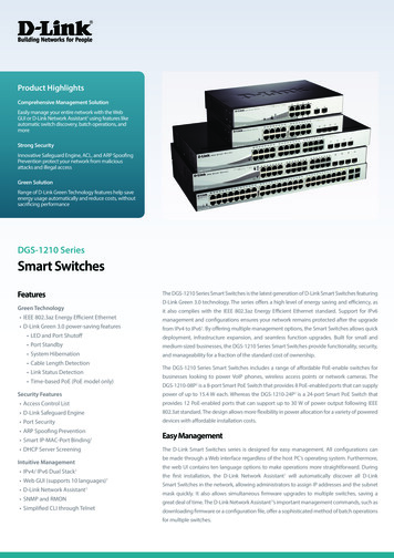
can a larger bandwidth be created, but other less critical traffic canbe limited, so bandwidth can be saved. The Switch has separatehardware queues on every physical port to which packets fromvarious applications are mapped to and assigned a priority. Theillustration below shows how 802.1P priority queuing isimplemented on the Switch. The eight IEEE 802.1P priority levelsdefined by the standard are mapped to the four class queues usedin the Switch.Mapping QoS on the SwitchThe picture above shows the default priority setting for the Switch.Class-3 has the highest priority of the four priority queues on theSwitch. In order to implement QoS, the user is required to instructthe Switch to examine the header of a packet to see if it has theproper identifying tag tagged. Then the user may forward thesetagged packets to designated queues on the Switch where they willbe emptied, based on priority."The DUT support strict mode for 802.1p QoS. The untagged pktwill follow the priority 0 to work (i.e. class 1)."Understanding QoSThe Switch has four priority queues. These priority queues arelabeled as 3, the high queue to 0, the lowest queue. The eightpriority tags, specified in IEEE 802.1p are mapped to the Switch'spriority tags as follows: Priority 0 is assigned to the Switch's Q1 queue.4
Priority 1 is assigned to the Switch's Q0 queue. Priority 2 is assigned to the Switch's Q0 queue. Priority 3 is assigned to the Switch's Q1 queue. Priority 4 is assigned to the Switch's Q2 queue. Priority 5 is assigned to the Switch's Q2 queue. Priority 6 is assigned to the Switch's Q3 queue. Priority 7 is assigned to the Switch's Q3 queue.The Switch uses strict priority for Scheduling. Strict priority-basedscheduling, any packets residing in the higher priority queues aretransmitted first.D-Link Green Technology IEEE 802.3az Energy-Efficient Ethernet (EEE):It is the first standard in the history of Ethernet to addressproactive reduction in energy consumption for networkeddevices. The IEEE 802.3 EEE standard defines mechanismsand protocols intended to reduce the energy consumption ofnetwork links during periods of low utilization, by transitioninginterfaces into a low-power state without interrupting the networkconnection. EEE : D-Link provides an EEE function allowing the user to reduceenergy when the device is at low utilization and the linkpartner is a non-EEE compliance switch. By default, the EEE function is disabled. Users canmanually turn on the EEE function by the switch on the frontpanel to enable power savings. Power Saving Technology: Power saving by link status.If there is no link on a port, such as when there is nocomputer connected to the port or the connected computer is5
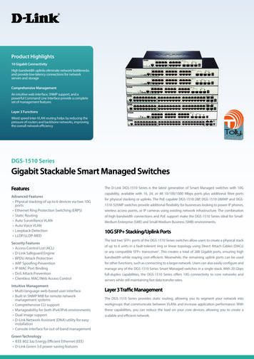
powered off, D-Link’s Green Technology will enter a "sleepmode", drastically reducing power used for that port. Power saving by cable length: 0 20m, 21 100m.D-Link’s Green Technology detects the length of connectedEthernet cable and adjusts power usage accordingly withoutaffecting performance. This way, a port connected to a 20mcable only uses as much power as it needs, instead of usingfull power, which is only needed for 100m cables.Front-Panel ComponentsOn the front panel of the Switch you will see the following. LED status indicators 16 Auto-Negotiating 10/100/1000Mbps ports on the DGS1016D 24 Auto-Negotiating 10/100/1000Mbps ports on the DGS1024D EEE on/off switch: By default, the EEE mode is disabled.Front Panel View of the SwitchLED IndicatorsThe LED indicators of the Switch include a Power status indicatorand Link/Act/Speed indicator for each port. When the Switch ispowered on or restarted, it initiates a diagnostics function as part ofthe boot up process. The Link/Act/Speed indicators are also used todisplay Cable Diagnostics information when the Switch boots up.6
LED Indicators7
Cable DiagnosticsWhen the Switch is booted up (when the Switch is first powered on),the Cable Diagnostics function is initialized and run. The CableDiagnostics function will detect two common faults in an Ethernetcable connecting the Switch to a remote network device: an opencircuit (a lack of continuity between the pins at each end of theEthernet cable or a disconnected cable), and a short circuit (two ormore conductors short-circuited). Any of these common cable faultswill be detected by the Cable Diagnostics function and the LEDs willdisplay the results of the Cable Diagnostics function as follows:Open or Short circuit- Link/Act/Speed: AmberCable Connection in good status- Link/Act/Speed: GreenDuring the diagnostics, each port is scanned to determine if theEthernet cable and connectors is in good working order. During thediagnostics process the LED for each port blinks green insequential order. If a cable fault is detected, the correspondingport’sLink/Act/Speed LED will light amber. The Switch then goes for normaloperation.NOTE: the Cable Diagnostics function does notdetect the length of Ethernet cabling. Rememberthat the length of cabling between two Ethernetdevices may not exceed 100 meters (or 300 feet).8
LED IndicatorDescriptionPowerThis lights green while the Switch isreceiving power.Link/Act/SpeedWhen connected to a 1000Mbps device, this LEDindicator light is green when the port is connectedto a device and will blink as data is transmitted orreceived.When connected to a 10/100Mbps device, thisLED indicator light is amber when the port isconnected to a device and will blink as data istransmitted or received.Cable Diagnostics(during boot up only)Open or short circuit Link/Act/SpeedLED light amber9
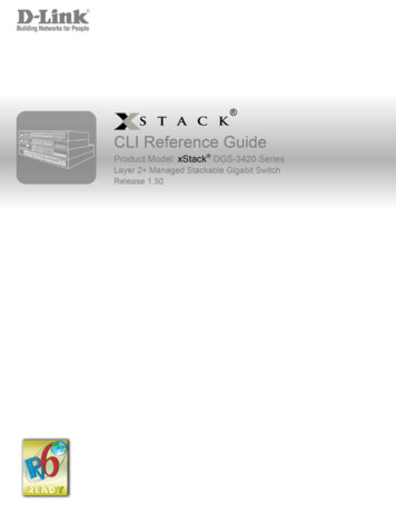
Power Input on Rear PanelThe power cable connection is located on the rear panel of theSwitch.Rear panel view of the Switch‧Switch power input is provided by and internal universal powersupply (100-240VAC, 50-60Hz, 0.4A Max : 12V/2A).The AC power connector is a standard three-pronged connectorthat supports the power cord. Please see the Power On sectionbelow for instructions on how to properly connect the Switch to apower source.‧Kensington Security SlotDGS-1016D/24D has been giving customers the best option forphysical security through a Kensington Security Slot in the rearpanel. The Kensington Security Slot adds value to DGS-1016D/24Dby offering customers a simple, built-in security solution.Grounding the SwitchThis section describes how to connect the switch to ground. Youmust complete this procedure before powering your switch.Required Tools and Equipment‧ Ground screws (included in the accessory kit): One M4 x 6 mm(metric) pan-head screw10
‧ Ground cable (not included in the accessory kit): The groundingcable should be sized according to local and nationalinstallation requirements. Depending on the power supply andsystem, a 12 to 6 AWG copper conductor is required for U.Sinstallation. Commercially available 6 AWG wire isrecommended. The length of the cable depends on theproximity of the switch to proper grounding facilities.‧ A screwdriver (not included in the accessory kit)The following steps let you connect the switch to a protectiveground:Step 1: Verify if the system power is off.Step 2: Use the ground cable to place the #8 terminal lug ring ontop of the ground-screw opening, as seen in the figure below.Step 3: Insert the ground screw into the ground-screw opening.Step 4: Using a screwdriver, tighten the ground screw to secure theground cable to the switch.Step 5: Attach the terminal lug ring at the other end of thegrounding cable to an appropriate grounding stud or bolt on rackwhere the switch is installed.Step 6: Verify if the connections at the ground connector on theswitch and the rack are securely attached.11
SECTION 2InstallationPackage ContentsBefore You Connect to the NetworkInstalling the SwitchPower OnPackage ContentsOpen the shipping carton of the Switch and carefully unpack itscontents. The carton should contain the following items: One DGS-1016D 16-Port/DGS-1024D 24-Port10/100/1000BASE-T Gigabit Ethernet SwitchFour rubber feet with adhesive backingOne power CordMounting ears for rack-mountingQuick Install GuideIf any item is found missing or damaged, please contact your local DLink reseller for replacement.12
Before You Connect to the NetworkThe site where you install the Switch may greatly affect itsperformance. Please follow these guidelines for setting up theSwitch. Install the Switch on a sturdy, level surface that can supportat least 3 kg (6.6 lbs) of weight. Do not place heavy objectson the Switch. The power outlet should be within 1.82 meters (6 feet) ofthe Switch. Visually inspect the power cord and see that it is fullysecured to the AC power port. Make sure that there is adequate space for proper heatdissipation from and adequate ventilation around the Switch.Leave at least 10 cm (4 inches) of space at the front andrear of the Switch for ventilation. Do not place any device on top of Switch, or place theSwitch on top of any device or object that will block the freeflow of air through the ventilation slots on the sides, top,and bottom of the Switch’s case. Keep your hand away from top and bottom of device thatgenerates a significant amount of heat. Install the Switch in a fairly cool and dry place for theacceptable temperature and humidity operating ranges. Install the Switch in a site free from strong electromagneticfield generators (such as motors), vibration, dust, and directexposure to sunlight. When installing the Switch on a level surface, attach therubber feet to the bottom of the device. The rubber feetcushion the Switch, protect the casing from scratches andprevent it from scratching other surfaces.13
Mounting the Switch on a RackThe DGS-1016D/1024D can easily be mounted on a rack. Twomounting ears are provided for this purpose. Make sure that thefront panel is exposed in order to view the LEDs. Please refer to thefollowing illustrations:Mounting the Switch to a Rack1. Attach the ears to each side of the Switch, using the screwholes located on the side of the device.14
2. Firmly attach the ears to the rack as shown. Please follow theusual safety precautions for rack-mountable productsAttaching the Rubber FeetUse rubber feet provided. Position and apply rubber feet to theunderside of the DGS-1016D/1024D Switch.Attaching the Rubber FeetProvide for Adequate VentilationCAUTION: Do not place any device on top of Switch,or place the Switch on top of any device or object thatwill block the free flow of air through the ventilationslots on the sides, top, and bottom of the Switch’scase. In addition, care should be taken not to locatethe Switch next to, on top of, or underneath anydevice that generates a significant amount of heat.For the Switch to perform at its optimal level, theSwitch must have adequate ventilation to prevent theSwitch from overheating and becoming damaged.15
Power OnTo power on the Switch, Plug-in the female connector of theprovided power cord into this socket, and the male side of the cordinto a suitable power source.After the Switch is powered on, the LED indicators will blink brieflywhile the system resets.Power FailureAs a precaution, in the event of a power failure, unplug the Switch.When power is resumed, plug the Switch back in.16
Section 3Connecting the SwitchSwitch to End NodeSwitch to Hub or SwitchConnecting to a ServerNOTE: All Ethernet ports auto-detect MDI/MDIX, portspeed (10, 100, 1000Mbps) and duplex of the deviceconnected to the Switch.Cable QualityFor all connections to the Switch, use these rules to determine the
D-Link DGS-1016D/DGS-1024D Unmanaged Gigabit Ethernet Switch iv Preface The DGS-1016D/DGS-1024D Manual is divided into sections that describe the system installation and operating instructions with examples. Section 1, Introduction - A description of the physical features of the Switch, including LED indicators, ports and panel descriptions.