Transcription
An overviewof the basicprlnclplesof the Q-Coderadaptive binaryarithmetic coderby W. B. PennebakerJ. L. MitchellG. G. Langdon, JrR. B. ArpsThe Q-Coder is a new form of adaptive binaryarithmetic coding. The binary arithmetic codingpart of the technique is derived from the basicconcepts introduced by Rissanen, Pasco, andLangdon, but extends the coding conventions toresolve a conflict between optimal software andhardware implementations. In addition, a robustform of probability estimation is used in whichthe probability estimate is derived solely fromthe interval renormalizations thatare part of thearithmetic coding process. A brief tutorialofarithmetic coding concepts is presented,followed by a discussion of the compatibleoptimal hardware and software codingstructures and the estimation of symbolprobabilities from interval renormalization.implementations. It also incorporates a new probabilityestimation technique which provides an extremely simple yetrobust mechanism for adaptive estimation of probabilitiesduring the coding process.This paper presents an overview of the principles of theQ-Coder. A brief discussion ofthe basic principles ofarithmetic coding is presentedin Section 2. A discussion ofthe coding conventions which lead to optimal, compatiblehardware and software implementations of arithmetic codingfollows in Section 3. In addition, Section 3 introduces someaspects of implementation using fixed-precisionarithmetic.Section 4 covers the estimation of probabilities by a newtechnique which uses onlythe interval renormalization thatis a necessary part of the finite-precision arithmetic codingprocess. Dynamic probability estimation makes the Q-Coderan adaptive binary arithmetic coder. Section 5 gives someexperimental results.1. IntroductionThe Q-Coder isan adaptive binary arithmetic coding systemwhich allows different,but compatible, coding conventionsto be used in optimal hardware and optimal software"Copyright 1988 by International Business Machines Corporation.Copying in printed form for privateuse is permitted withoutpayment of royalty provided that ( I ) each reproduction is donewithout alteration and (2) the Journal reference and IBM copyrightnotice are included on the first page. The title and abstract, but noother portions, of this paper may be copied or distributed royaltyfree without further permission by computer-basedand otherinformation-servicesystems. Permission to republish any otherportion of this paper must be obtained from the Editor.IBM 1. RES. DEVELOP. VOL. 32 NO. 6 NOVEMBER 19882. Basic principles of binary arithmetic coding'Traditionally, Huffman coding [2] is usedto code a sequenceof symbols which describesthe information beingcompressed. As an example, Figure 1 shows a possibleHuffman tree for a set of four symbols-w, x, y, and zwith respective probabilities 0.125,O. 125, 0.25, and 0.5. Thevertical axisof Figure 1 represents the number line from 0 to1, which isthe probability interval occupied by the foursymbols. Eachof the four symbols is assigneda subinterval' A much more extensive tutorial on arithmetic codingis found in [ 11.W. B. PENNEBAKER, J. L. MITCHELL, G. G . LANGDON, JR., AND R. B. ARF'S
BinarySymbol Probability Code 10.00000of size proportional to the probability estimate of thatsymbol. If each subinterval is identified byits least or basevalue, the four symbols are identified respectively bythebinary numbers 0.000,O.OO 1, 0.01, and 0.1. Note that thesubinterval size (or probability estimate) determines thelength of the code word.Ideally this length for some symbola is given by log,p,(a), where p,(a) isthe probability estimatefor symbol a. For the example in Figure 1, the probabilitieshave been chosen such that the code lengthsare ideal.The tree in Figure 1 is constructed in a particular way toillustrate a concept which is fundamental to arithmeticcoding: The code words,if regarded as binary fractions, arepointers to the particular interval being coded. In Figure 1the code wordspoint to the base of each interval. Thegeneral concept that a code string can be a binary fractionpointing to the subinterval for a particular symbol sequenceis due to Shannon [3] and was applied to successivesubdivision of the interval by Elias [4]. The idea ofarithmetic coding, derivedby Rissanen [ 5 ] from the theoryof enumerative coding, was approached by Pasco [6] as thesolution to a finite-precision constraint on the intervalsubdivision methods of Shannon and Elias.Any decision selectingone symbol from a set of two ormore symbolscan be decomposed into a sequence of binarydecisions. For example, Figure 2 shows two possibledecompositions of the four-symbol choiceof Figure 1. Froma coding-efficiency point of view there is no differencebetween the two alternatives, in that theinterval size andposition on the number line are the same for both. However,from the point of view of computational efficiency,decomposition (a) is better. Fewer computations are requiredto code the most probable symbol.Thus, although theHuffman coding tree is not required to achieve efficientcompression, it remains useful as an approximate guide forminimizing the computational burden.In general,as coding of each additional binary decisionoccurs, the precision of the code string must be sufficienttorziWO"ZfmO'olYO"0I- 0.01I0.0010.0010.0000.000YW(b)W. B. PENNEBAKER, J.L. MITCHELL, G. G. LANGDON,JR., ANDR. B.ARPSIBM J.RES. DEVELOP. VOL. 32NO. 6 NOVEMBER 1988
provide two distinguishablepoints within the subintervalp ( s ) allocated to the sequence of symbols, s, which actuallyoccurred. The number of bits, b, required to express the codestring is then given by [3]4Symbol:MLLM 2bp(s)2 2,which can be rewritten usingthe left inequality asb 2 - log,(p(s)).After many symbols are coded, p(s) becomes very small,and the code-string lengthrequired to express the fractionapproaches the ideal value of- log&).An example of Elias coding is shownin Figure 3 for thebinary decision sequence, M L L M, where M is the moreprobable symbol (MPS) and L is the less probable symbol(LPS). The interval subdivision in Figure 3 is ageneralization of that in Figures 2(a)and (b). The intervalsubdivision process is definedin terms of a recursion thatselects one subinterval as the new current interval. Therecursive splitting of the current interval continues until alldecisions have been coded. By convention, as in Figure 1,the code string in Figure 3 is defined to point at the base ofthe current interval. The symbol-ordering convention isadopted from [7], where the MPS probability estimate, P,,isordered above the LPS probability estimate, Qe, in thecurrent interval. The translation of the 0 and 1 symbols intoMPS and LPS symbols and the subsequent ordering of theMPS and LPS subintervals is important for optimalarithmetic coding implementations [8].After each symbol is coded, the probability intervalremaining for future coding operations is the subinterval ofthe symbol just coded. If the more probable symbol M iscoded, the interval allocated to the less probable symbol Lmust be added to the code-string value so that it points tothe base of the new interval.Arithmetic coders such as the Q-Coder avoid theincreasing-precision problemof Elias coding by using afixed-precisionarithmetic. Implementation in fixed-precisionarithmetic requires that a choice be made for the fixedprecision representation of the interval. Then, arenormalization rule must be devised which maintains theinterval size within the bounds allowed by the fixed-precisionrepresentation. Both the code string and the interval sizemust be renormalized identically, or the identification of thecode string as a pointer to the current interval will be lost.Efficiency of hardware and software implementationssuggests that renormalization be done using a shift-leftlogical operation.The Elias decoder maintains the same current-interval sizeas the encoder, and performs the same subdivision intosubintervals. The decoder simply determines, for eachdecision, the subinterval to which the code string points. Forfinite-precision implementations following the codingconventions above, however, the decoder must subtract any“I/\Code string0.0interval added by the encoder, after decoding a givensymbol. The code-string remainder will be smaller than thecorresponding current-interval measure, since it is a pointerto a particular subinterval within that interval.Renormalization then keeps the precision of the arithmeticoperations within the required bounds. Decoderrenormalization must be the same as in the encoder.Another problem to be resolved for implementation infixed-precisionarithmetic is a carry propagation problem. Itis possible to generate a code string with a consecutivesequence of 1-bits of arbitrary length. If a bit is added to theleast significantbit of this sequence, a carry will propagateuntil a 0-bit is encountered. Langdon and Rissanen [8]resolved this problem by “bit stuffing.” If a sequence of 1bits of a predefined maximum length is detected, an extra 0bit is stuffedinto the code string. The stuffed 0-bit acts as acarry trap for any carry from future coding operations. Thedecoder, after detecting this same sequence, removesthestuffed bit, adding any carry contained in it to the codestring remainder. The Q-Coder follows this general scheme,but with the additional constraints that the string of 1-bits iseight bitsin length and is byte-aligned.One final practical problem needs to be resolved. Ingeneral, arithmetic coding requires a multiply operation toscale the interval after each coding operation. Generally,multiplication is a costly operation in both hardware andsoftware implementations. An early implementation ofadaptive binary arithmetic coding avoided multiplication [8].However, the Skew Coder [7] uses an even simplerapproximation to avoid the multiply; the sameapproximation is used in the Q-Coder. If renormalizationsare used to keep the current interval, A, of order unity, i.e.,in the range 1.5 A z 0.75, the multiplications required toW. B. PENNEBAKER, I. L. MITCHELL, G. G. I .ANGlWN, IR., AND R. B. A,RPS719
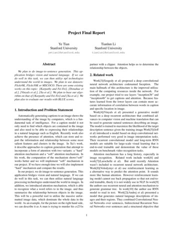
3. Q-Coder hardware and software codingconventions0.100.08s. 5-12-bit quantizationonly0.06----- 5-bit granularity added.-8M 0.04V0.020.00* J. J. Rissanen, IBM Almaden Research Center, San Jose, CA, privatecommunication.W. 8. PENNEBAKER, J. L. MITCHELL, G. G. LANGDON, JR., AND R. B. ARPSThe description of the arithmetic coder and decoder in thepreceding sectionis precisely that of a hardware-optimizedimplementation of the arithmetic coder in the Q-Coder. Ituses the same hardware optimizations developed for theearlier Skew Coder [7]. A sketch of the unrenormalizedcode-string development is shown in Figure 5(a), and asketch of the corresponding decoding sequence isfound inFigure 5(b). Note that the coding (and decoding) processrequires that both the current code string and the currentinterval be adjusted on the more probable symbol path. Onthe less probable symbol path only the current interval mustbe changed.The extra operations for the MPS path do not affecthardware speed,in that the reduction in the interval size andthe addition to (or subtraction from) the code string can bedone in parallel. The illustration of the hardware decoderimplementation in Figure 6(a) shows this parallelism.However, this organization is not as good for software.Having more operations on the more probable path, as seenin the decoder flowchart of Figure 7(a), can be avoided.Software speedcan be enhanced by exchangingthe locationof subintervals representing the MPS and LPS. As illustratedin Figure 7(b), the instructions on the more probable pathare reduced to a minimum and, instead, more instructionsare needed on the less probable path. Note that thisorganization gives slower hardware, in that two serialarithmetic operations must be done on the LPS path [seeFigure 6(b)]. To decode, first the new MPS subinterval size iscalculated, then the result is compared to the code string.If the choices were limited to the two organizationssketched in Figures 6 and 7, there would be a fundamentalconflict between optimal hardware and softwareimplementations. However, there are two waysto resolvethis conflict [9]. First, it is possible to invert the code stringcreated for one symbol-ordering convention, and achieve acode string identical to that created with the oppositeconvention. A second (and simpler) technique uses the samesymbol-ordering convention for both hardware and software,but assigns different code-stringpointer conventions forhardware and software implementations. The code-stringconvention shown in Figure 5(a), in which the code string ispointed at the bottom of the interval, is used for hardwareimplementations. However, a different code-stringconvention, illustrated in Figure 8(a), is used for software. Inthis software code-stringconvention the code string ispointed at the top of the interval. When the software codestring convention is followed,coding an MPS does notchange the code string, while coding an LPS does. Figure8(a) also shows the relationship between hardware andsoftware code strings. Note that the gap between the twocode stringsis simply the current interval.IBM J. RES. DEVELOP. VOL. 32 NO, 6 NOVEMBER 1988
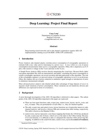
Q, indexQ, index139E-:UnderflowMUXCODEINIBM J. RES.DEVELOP.VOL.,!II(MPS) DATA OUT1/"32 NO. 6 NOVEMBER 1988cW. B. PENNEBAKER, J. L. MITCHELL, GG.LANGWN, JR., AND R. B. A R E
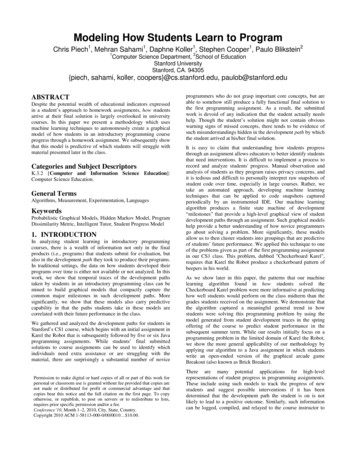
STARTiiSTARTA"A-QA 5 C?A"A - QTEST(A): e:RENORMALIZE TEST(A): RENORMALIZE? RENORMALIZE Inner-loop trade-offs: (a) Hardware-optimized MPS and LPS subinterval ordering. (b) Software-optimized MPS and LPS subinterval ordering.NO)Software code string" QCHardware code stringvSymbol: MMLM(a)722The addition operation required when generating a codestring following the hardware convention creates a problemwith carry propagation, Conversely, the subtractionoperation required whenfollowing the software conventionW. B. PENNEBAKER, 1. L. MITCHELL, G.G.LANGDON, JR., AND R. B. ARPScreates a problem with borrow propagation. Borrowpropagation could be blocked by stuffing a 1-bit followingastring of 0-bits, but the code strings generated usingthe twoconventions would then be incompatible.IBM J. RES.DEVELOP.VOL.32 NO. 6 NOVEMBER 1988
Compatibility (and, in fact, identity) of the hardware andsoftware codestrings can be achieved as follows [9]: In bothcases the code string is partitioned into two parts, a codebuffer which contains the high-order bytesof the code string,and a code register which contains the low-order bitsof thecode string. The hardware convention for bit stuffingrequires that if R,the byte most recentlytransferred fromthe code register to the code buffer, cannot allow theaddition of a carry bit (i.e,, X’FF’), the leading bit of thenext byte must become a stuffed 0-bit.In software the problem is borrowpropagation. Theconvention is adopted that, by definition, if a borrow isneeded from the byte most recentlytransferred from thecode register,it can be taken. The only byte value whichcannot supply a borrow is 0. Consider the case where a 0byte is to be transferred from the code register to the codebuffer. Note that the difference between softwareandhardware code stringsis the value in the probability intervalregister, and this interval value (by definition) must besmaller than the least significant bit of the byte beingtransferred. Therefore, for the special case wherethe byteabout to be transferred is 0, only two possibilities exist forthe software code string relative to the hardware code R,00,’ ‘’ ’hardwarecodestringorcode buffercode reaisterOO,.”codesoftwarestring(b). , R ,IFF :.hardwarecodestringThese two cases can be differentiated bycomparing the coderegister with the interval register. If the code register is lessthan the interval register, case (b) has occurred; otherwise,case (a) has occurred. If case (b), a borrow is taken from theX’OO’ byte (converting it to X’FF‘) and propagated toR 1 (reducing it to R).For both hardware and softwarecode strings, the X’FF’ byte triggers bit stuffing. However,in hardware a 0-bit is stuffed, whilein software a 1-bit isstuffed. As coding proceeds,either a borrow will besubtracted from the software stuff bitor a carry will beadded to the hardware stuff bit. The code strings thenbecome identical.To work with fixed precision,the decoder must “undo”the actions of the encoder. The hardware decoder thereforesubtracts any LPS interval the encoder added. Similarly,since for the LPS operation the software encoder subtractsIBM J. RES. DEVELOP. VOL. 32 NO. 6 NOVEMBER 1988the MPS interval when coding, the software decoder mustadd this interval. If the software decoder initial conditionssimply emulated the hardware decoder, the software coderemainder would approach A(0) instead of 0. Since A ( 0 ) getsvery large relativeto the current interval as coding proceeds,a problem with arithmetic precision would quickly occur.Instead, the software decoder remainder is initialized to-A(O) at the start of coding. Addingthe MPS interval thenmoves the remainder toward 0. The decoder comparison isdone with a negative remainder and a negative interval, assketched in Figure 8(b). However, sinceboth remainder andinterval approach zero (and are periodically renormalized),there is no problem with precision. Note that the gapbetween the remainders of the hardware and softwaredecoders isthe current interval.4. Probability estimationAdaptive arithmetic coding requires that the probability bere-estimated periodically.This very important conceptdynamic probability estimation-was developed in earlierarithmetic coding implementations [7, 8, 10-121. Thecurrent technique, when applied to mixed-context coding,generally falls in the class of so-calledapproximate countingmethods [lo, 12, 131.The probability-estimationtechnique used in the Q-Coderdiffers from the earlier techniques in that the estimates arerevised only during the interval renormalization required inthe arithmetic coder [ 141. Estimation only atrenormalizations is very important for efficient softwareimplementations. The inner loop of the coder is thenminimized. Since eachrenormalization produces at least onecompressed-databit, the instruction cycles expended on theestimation process are related to the compressed-data codestring length.By definition, both encoder and decoder renormalize inprecisely the same way. Furthermore, renormalizationoccurs following both the MPS (occasionally) and the LPS(always).The estimation process isimplemented as a finitestate machine of 60 states. Half of the states are for an MPSof 1, and the other half are for an MPS of 0. Each state k ofthe machine has a less probable symbol probability estimate,Q,(k), associated withit. After the LPS renormalization, theestimate is increased; after the MPS renormalization, theestimate is decreased.Table 1 gives the set of allowed values for the LPSprobability estimate. This particular set of values is the result of a lengthy optimization procedure involving both theoretical modeling [ 141 and coding of acutal data generatedby binary and continuous-tone image-compression model . The values are given as hexadecimal integers, wherea scalingis used suchthat the decimal fraction 0.75 is equivalent to’G. Langdon was the first to show that the estimation process in[ 141 could be usedwith such a sparse finite-state machine. He initiated the effortto simplify thisalgorithm, and contributed significantly to the setof values in TableI .W.B. PENNEBAKER,J. L. MITCHELL, G. G. LANGWN, JR., ANDR. B. ARPS
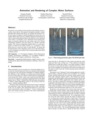
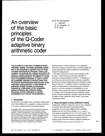
Table 1 Q-Coder LPS probabilityestimatevaluesandassociated LPS renormalization index ’X’OOO1’The interval register is decremented by the current LPSprobability estimate Qefollowing eachMPS. After Nm,symbols, the MPS renormalization occurs, givingdk33hexadecimal 1000. This particular scaling provides easeofhardware implementation and leads to a convenient rangefor the interval register A of hexadecimal 1000 to I FFF(corresponding to the decimal range of 0.75 5 A IS). Forsimplicity, a convention was adopted that MPSrenormalization always shiftsthe LPS estimate to the nextsmaller value;the column labeled dk, which gives the changein table position (to larger Q,) following LPSrenormalization, was then derived as part of theoptimization procedure.Each state in the finite-state-machineestimation processmust have a unique index. A five-bit index which selectsoneof 30 Q, values from Table 1, together with one bit whichdefines the sense of the MPS, completely describesthecurrent state of the estimator. This six-bit index is allthat isrequired in a hardware implementation.One particularly efficient softwareimplementation of thisfinite-state machine uses two tables, one for the MPSrenormalization and one for the LPS renormalization. Eachtable entry is four bytes, where the first two bytesare thenew estimate Q, and the next two bytesare the index to beused at the next renormalization. The estimation process is,therefore, nothing more than an indexed lookup of a fourbyte quantity from one of two tables.An approximate understanding of the principles ofoperation of this estimation process can be gained from thefollowing a r g m e n tUnlike. the earlier estimationtechniques, which require some estimation mechanismexternal to the arithmetic coder, the Q-Coder’s approximatesymbol counting is imbedded in the arithmetic codingprocess itself. The counter for the MPS is the interval registerA . The LPS counter is a one-bit counter which is setby theLPS renormalization.‘In developing thisexplanation,the complicationsintroduced by the exchangeof724MPS and LPS definitionswhen the estimate wouldexceed 0.5 are ignored; thetruncation of the finite-state machine at the minimum LPS value is also ignored.w.B.PENNEBAKER, I. L. MITCHELL, G. G. LANGDON, JR., AND R. B. A R BIf,,,, d/Q,,where dA is the change in the interval register betweenrenormalizations. Define the finite-state-machineorganization such that increasing state index, k, correspondsto decreasing Q,. The finite-state machine is also restrictedsuch that on the MPS renormalization path only a unitchange in k is allowed.On the LPS path, however, thechange in index, dk, can be 1,2, or 3. For balance of theestimator, dk MPS renormalizations must occur for eachLPS renormalization. Thus, for one LPS event, the numberof MPSs must beNm, [ A - 0.75 0.75(dk - l)]/Qe,where A is the starting interval after the LPSrenormalization. We assume Q, does not change very muchfrom one state to the next if dk 1. The estimator will bebalanced whenthe true probability q is approximately equalto the estimate4 MNm, 1) Q,.Thus, near q 0.5, dk 1 for a good balance ( A is of theorder of 1.125 on the average). For q 0.5, dk 2 for agood balance. The values for dk in Table 1 show thisqualitative behavior. At very small valuesof Q,, dk 3 forsome entries, but this is a result of optimization in realcompression experiments, where the increased estimationrate for dk 3 becomes important.Figure 9 shows the coding inefficiency for the finite-statemachine corresponding to Table 1. The solid curve is theresult of an exact modelingof this state machine [9]; thedata points are from a Monte Carlo simulation using a realcoder and pseudorandom data sets. The coding inefficiencyis of the order of 5-6%, the inefficiency beingdominated bythe granularity of the set of allowed probability estimates(only 30), rather than by any inaccuracy in the estimationprocess. This granularity represents the best compromise wecould find between goodcoding of statistically stable systemsand rapid estimation of dynamically varying systems.In most data-compression systems,conditioning states orcontexts are used with independent probability estimates foreach context. In the Q-Coder, a different six-bitindex (or, insoftware, a four-byte storage unit) is kept for each context.However, the renormalization of the interval register is usedto generate individual estimates for all of theseseparatecontexts. The approximate analysis above ignores the effectsof these independent contexts on the estimation process. Anapproximate model and experimental data for the influenceof multiple contexts are given in [ 141.5. Some experimental resultsTable 2 lists some experimental results for the Q-Coder fortwo important classes of image models.The results for gray-IBM I. RES.DEVELOP.VOL. 32 NO. 6 NOVEMBER 1988
scale compression show that the Q-Coder provides goodcompression, slightly improving upon the performanceachieved with a version of arithmetic coding which used afull multiplication in both arithmetic coding and probabilityestimation [ 151.The results for facsimileimage compression using a 7-pelneighborhood model [8] and the Q-Coder are alsosummarized. This algorithm for adaptive bilevel imagecompression (ABIC) has been successfully implemented in ahigh-speed VLSI chip [ 161, using the hardware-optimizedform of the Q-Coder. Here, the results are much better thancan be achieved with the CCITT G-4 facsimile algorithm,and are even better than the stationary entropy for themodel. Compressing to better than the stationary entropy isa direct result of the adaptive dynamic probabilityestimation. The compression achieved with the Skew Coderis almost identical to that listed here for the facsimiledocuments PTT 1-PTT8. However, theQ-Coder fares better on the gray-scale imagesand also onthe statistically unstable binary halftone images.0.100.08xfi. 0.06E.-8OD. 0.04u0.020.006. SummaryA brief overview ofthe Q-Coder has been presented. Thesame material is covered in much greater depth in thecompanion papers of this issue ofthe ZBM Journal ofResearch and Development [9, 14, 16, 171 and in previoustutorials [ 1, 181. This paper is intended to provide a broadoverview of the concepts involved. In addition to the tutorialand the description of the parts of the Q-Coder derived fromearlier arithmetic coders such as the Skew Coder, two mainpoints have been summarized-the compatible codingconventions for hardware and software implementations,and the probability-estimation technique.Table 2 Compression performance relative to alternativetechniques.Gray-scale image compressionDPCMlQ-Coder(bits)References1. G. G. Langdon, “An Introduction to Arithmetic Coding,” IBMJ. Res. Develop. 28, 135 (1 984).2. D. A. Huffman, “A Method for the Construction of MinimumRedundancy Codes,” Proc. IRE 40, 1098 (1952).3. C. E. Shannon, “A Mathematical Theory of Communication,”Bell Syst. Tech. J. 27, 379 (1948).4. P. Elias, in N. Abramson, Information Theory and Coding,McGraw-Hill Book Co., Inc., New York, 1963.5. J. J.Rissanen, “Generalized Kraft Inequality and ArithmeticCoding,” IBM J. Res. Develop. 20, 198 (1976); first published asIBM Research Report RJ-1591, June 1975.6. R. C. Pasco, “Source Coding Algorithms forFast DataCompression,” Ph.D. Thesis, Department of ElectricalEngineering, Stanford University, Stanford, CA, May 1976.7. G. G . Langdon and J. J. Rissanen, “A Simple General BinarySource Code,” IEEE Trans. Info. Theory IT-28, 800 (1982).8. G. G. Langdon and J. J. Rissanen, “Compression of BlackWhite Images with Arithmetic Coding,” IEEE Trans. Commun.COM-29, 858 (1981).9. J. L. Mitchell and and W. B. Pennebaker, “Optimal Hardwareand Software Arithmetic Coding Procedures for the Q-Coder,”IBM J. Res. Develop. 32, 727 (1988, this issue).10. D. R. Helman, G. G. Langdon, N. Martin, and S. J. P. Todd,“Statistics Collection for Compression Coding withRandomizing Feature,” IBM Tech. Disclosure Bull. 24, 4917(1982).IBM J. RES. DEVELOP. VOL. 32 NO, 6 NOVEMBER 1988Total, 13images2 120288Entropy(bits)Reference [I51(bits)2 074 0472 138 864Bilevel image compressionABICEntropy(bits)(bits)Total, CCITT 1-8Total, 6 halftones1 7470081 841 921157 952CCITT G-4(bits)2 1131282 333 31211. G. G. Langdon and J. J. Rissanen, “A Double-Adaptive FileCompression Algorithm,” IEEE Trans. Commun. COM-31,1253-(1983). 12. P. Flaiolet. “Amroximate Counting:- A Detailed Analysis,” BIT2s,1 i3( l k i13. S. J. P. Todd, G. G. Langdon, D. R. Helman, and N. Martin,“StatisticsCollection for Compression Coding withRandomizing Feature,” Research Report RJ-6414, IBMAlmaden Research Center, San Jose, CA, August 1988.14. W. B. Pennebaker and J. L. Mitchell, “Probability Estimationfor the Q-Coder,” IBM J. Res. Develop. 32, 737 (1988, thisissue).W. B. PENNEBAKER, J. L. MITCHELL, G.G. LANGDON, JR.,AND R. B. A R B725
15. D. Anastassiou, J. L. Mitchell, and W. B. Pennebaker, “GrayScale Image Codingfor Free-Frame Videoconferencing,”IEEETrans. Commun. COM-34, 382 (1986).16. R. Arps, T. K. Truong, D. J. Lu, R. C. Pasco, andT. D.Friedman, “A Multi-Purpose VLSI Chip for Adaptive DataCompression of Bilevel Images,” IBM J. Res.Develop. 32, 775(1988, this issue).17. J. L. Mitchell and W. B. Pennebaker, “SoftwareImplementations of the Q-Coder,” IBM J. Res.Develop. 32, 753(1988, this issue).18. G. G. Langdon, W. B. Pennebaker, J. L. Mitchell, R. B. Arps,and J. J.Rissanen, “A Tutorial on the Adaptive Q-Coder,”Research Report RJ-5736, IBM Almaden Research Center, SanJose, CA, July 1987.Received March 11, 1988; acceptedfor publicationSeptember 2, 1988William B. Pennebaker IBM Research Division, T. J. WatsonResearch Center, P.O. Box 218, Yorktown Heights, New York 10598.Dr. Pennebaker is a Research Staff Member at the IBM T. J
arithmetic coding process. A brief tutorial of arithmetic coding concepts is presented, followed by a discussion of the compatible optimal hardware and software coding structures and the estimation of symbol probabilities from interval renormalization. 1. Introduction The Q-Coder is an adaptive binary arithmetic coding system