Transcription
SMC8014W-GUser ManualPage 1 of 39
CopyrightInformation furnished by SMC Networks, Inc. (SMC) is believed to be accurate and reliable.However, no responsibility is assumed by SMC for its use, nor for any infringements of patentsor other rights of third parties which may result from its use. No license is granted byimplication or otherwise under any patent or patent rights of SMC. SMC reserves the right tochange specifications at any time without notice.Copyright 2009 bySMC Networks, Inc.20 MasonIrvine, California 92618All rights reserved.TrademarksSMC is a registered trademark of SMC Networks, Inc. Other product and company names are trademarksor registered trademarks of their respective holders.Page 2 of 39
TABLE OF CONTENTSCHAPTER 1 IntroductionFeatures and BenefitsPackage ContentsMinimum RequirementsCHAPTER 2 Getting to know the EZ Connect Wireless Cable Modem GatewayLED IndicatorsRear Panel DescriptionResetting and Restoring the EZ Connect Wireless Cable Modem GatewayCHAPTER 3 InstallationBasic Installation ProcedureCHAPTER 4 Configuring your ComputerConfiguring Windows 95/98/MeConfiguring Windows 2000Configuring Windows XPConfiguring Windows VistaConfiguring a Macintosh ComputerCHAPTER 5 Configuring the EZ Connect Wireless Cable Modem GatewayBrowser ConfigurationDisable Proxy ConnectionAccessing the EZ Connect Wireless Cable Modem Gateway Web ManagementCHAPTER 6 Navigating the Web-based tusAPPENDIX A Technical SpecificationsAPPENDIX B CompliancesAPPENDIX C Technical SupportPage 3 of 39
CHAPTER 1 IntroductionCongratulations on your purchase of the EZ Connect Wireless Cable Modem Gateway. SMC isproud to provide you with a powerful yet simple communication device for connecting yourlocal area network (LAN) to the Internet.Features and Benefits Internet connection to cable modem service via an integrated cable modem portLocal network connection via 10/100 Mbps Ethernet ports, USB 1.1 port, or 54 Mbpswireless802.11g - interoperable with multiple vendorsWireless WEP, WPA, and WPA2 encryption, Hide SSID, and MAC FilteringDHCP for dynamic IP configuration, and DNS for domain name mappingFirewall with Stateful Packet Inspection, client privileges, hacker prevention, DoS, andNATUser-definable application-sensing tunnel supports applications requiring multipleconnectionsBuilt-in Parental controls allow you to limit certain web sites – configurable by timeand dayEasy setup through a web browser on any operating system that supports TCP/IPCompatible with all popular Internet applicationsPage 4 of 39
Package ContentsBefore installing the EZ Connect Wireless Cable Modem Gateway, verify that you have theitems listed below. Also be sure that you have the necessary cabling. If any of the items aremissing or damaged, contact your local SMC distributor. 1 - EZ Connect Wireless Cable Modem Gateway1 - Power adapter (12V/1.25A)1 - CAT-5 Ethernet cableInstallation CD, including:o User Guideo USB DriversIf possible, retain the carton and original packing materials in case there is a need to returnthe product.System RequirementsYou must meet the following minimum requirements: Provisioned Internet access from a cable operator that has approved the SMC8014W-GA computer equipped with a wired network adapter with TCP/IP installedA Java-enabled web browser, such as Microsoft Internet Explorer 5.5 or aboveWindows 98 Second Edition or higher is required for USB driver support.Page 5 of 39
CHAPTER 2 Getting to Know the EZ Connect Wireless CableModem GatewayThe EZ Connect Wireless Cable Modem Gateway is the perfect all-in-one solution for the homeor business environment. This full-featured device has: An approved DOCSIS 1.1 and 2.0 cable modemAdvanced SPI Firewall GatewayHigh-speed 54 Mbps 802.11g Wireless Access PointComprehensive LEDs for network status and troubleshootingReset Button4 – 10/100 Mbps Auto-Sensing LAN ports with Auto-MDI/MDIX feature1 – USB 1.1 LAN Port for PC connectivityNOTE: Cable modems can provide up to 38 Mbps downstream and 10 Mbps upstream. However,you should note that the actual rate provided by specific service providers may varydramatically from these upper limits.LED IndicatorsThe Gateway includes LED indicators on the front panel that simplify installation and networktroubleshooting.LABELPowerLED COLORGreenDiagGreenCableGreenTrafficGreenWLANLAN (1-4)GreenGreenUSBGreenPage 6 of 39ONFLASHINGPower is supplied to theGatewayN/ASystem Failure. RebootGatewaySuccessfully connected tothe RF network –upstream rangingcompletedCable Modem has finishedCMTS registration.Internet connectivitycompletedWireless LinkConnected at 10 or 100MbpsUSB port connectedOFFPower is notsupplied to theGatewayN/ANormal OperationAttempting toconnect to RFnetworkN/AAttempting toregister with CMTSN/AData transmittingData transmittingData transmittingNo Wireless LinkNo Ethernet linkdetectedNo USB link detected
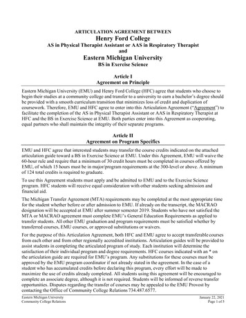
Rear Panel BItemPowerResetLAN 1-4USBCATVDescriptionConnect the included power adapter to this port.Use this button to reset the power or restore the default factory settings.Four 10/100 Auto-sensing switch ports (RJ-45). Connect devices on your localarea network to these ports (such as a PC, hub, or switch).Connect a USB Cable from your PC to this port.Connect your cable line to this port.Rebooting and Restoring the EZ Connect Wireless Cable Modem GatewayThe Reset button is located on the rear panel of the Gateway. Use a paper clip or a pencil tipto push the Reset button.RebootIf the Gateway is having problems connecting to the Internet, simply hold down the resetbutton for less than 2 seconds then release.Restore Factory DefaultsIf rebooting the Gateway does not resolve your issue, then you can follow these steps:1. Leave power plugged into the Gateway.2. Locate the reset button on the back panel, press and hold button for at least 10 seconds.3. Release reset button.Page 7 of 39
CHAPTER 3 InstallationThe EZ Connect Wireless Cable Modem Gateway can be installed in any location where youhave cable Internet access, and your cable Internet service provider has approved theGateway. To confirm you meet these 2 criteria points, please contact your cable operator.For general installation please follow the guidelines outlined below to best performance: Allow sufficient air flow around the device to assist in keeping the device as cool as possibleDo not place the Gateway in a dusty or wet environment.For optimum wireless performance, install the Gateway away from other electronicdevices, such as Monitors / TV / 2.4GHz Cordless Phones. These devices can hamperyour wireless throughput and distance.Basic Installation Procedure1. Connect the LAN: You can connect the Gateway to your PC, or to a hub or switch. RunEthernet cable from one of the LAN ports on the rear of the Gateway to your computer’snetwork adapter or to another network device. You can use either a standard straightthrough or crossover Ethernet cable since the Gateway incorporates Auto-MDI/MDIXfunctionality.2. Connect the WAN: Connect a coaxial cable to the CATV port on the back of the Gatewayfrom a cable port located in your home. When connecting to the CATV port, use onlymanufactured coaxial patch cables with F-type connectors at both ends for all connections.Note: If this modem was NOT installed by your cable provider (ISP) or is being used toreplace another cable modem – please contact your Cable Operator to register theSMC8014W-G. If the modem is not registered with your cable operator it will be unable toconnect to the cable network system.3. Power on: Connect the power adapter to the Gateway.Warning: Only use the power adapter that was provided with the Gateway! Using anotherpower adapter may damage your unit and void the warranty.Page 8 of 39
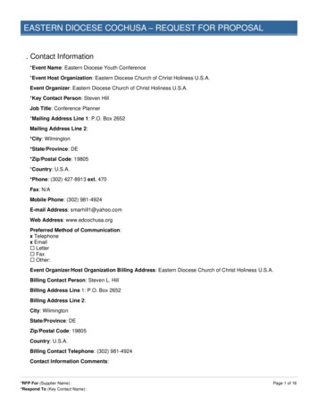
CHAPTER 4 Configuring your ComputerThe information outlined in this chapter will guide you through the configuration for thefollowing Operating Systems: Windows 95/98/ MeWindows 2000Windows XPWindows VistaApple MacintoshConfiguring Windows 95/98/Me1. Access your Network settings by clicking[Start], choose [Settings], and then select[Control Panel].2. In the Control Panel, locate and double-clickthe [Network] icon.3. Highlight the TCP/IP line that has beenassigned to your network card on the[Configuration] tab of the [Network]properties window. (see network dialog box tothe right)4. Next, click the [Properties] button to viewthat adapter’s TCP/IP settings.5. From the TCP/IP Properties dialog box, clickthe [Obtain an IP address automatically]option. (see TCP/IP dialog box to theright)6. Next click on the [Gateway] tab and verifythe Gateway field is blank. If there are IPaddresses listed in the Gateway section,highlight each one and click [Remove]until the section is empty.7. Click the [OK] button to close the TCP/IPProperties window.8. On the Network Properties Window, clickthe [OK] button to save these newchanges.NOTE: Windows may ask you for theoriginal Windows installation disk oradditional files. Check for the files atc:\windows\options\cabs, or insert your Windows CD-ROM into your CD-ROM drive andcheck the correct file location, for example, D:\win98, D:\win9x. (In this example “D”is your CD-ROM drive).9. Windows may prompt you to restart the PC. If so, click the [Yes] button. If Windowsdoes not prompt you to restart your computer, do so anyway to ensure your settings.Page 9 of 39
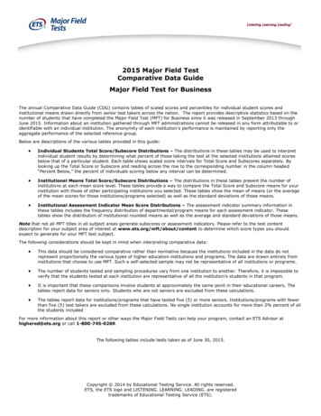
Configuring Windows 20001. Access your Network settings by clicking[Start], choose [Settings], and thenselect [Control Panel]2. In the Control Panel, locate and doubleclick the [Network and Dial-upConnections] icon3. Locate and double-click the [Local AreaConnection] icon for the Ethernetadapter that is connected to theGateway. When the Status dialog boxwindow opens, click the [Properties]button.4. On the [Local Area Connection]Properties box, verify the box next toInternet Protocol (TCP/IP) is checked.Then highlight the Internet Protocol (TCP/IP), and click the Properties button.5. Select Obtain an IP address automatically to configure your computer for DHCP. Clickthe [OK] button to save this change and close the Properties window.6. Click the [OK] button again to save these new changes.7. Reboot your PC.Configuring Windows XPThe following instructions assume you are running Windows XP with the default interface. Ifyou are using the Classic interface (where the icons and menus look like previous Windowsversions), please follow the instructions for Windows 2000 outlined above.1. Access your Network settings byclicking [Start], choose [ControlPanel], select [Network and InternetConnections] and then click on the[Network Connections] icon.2. Locate and double-click the LocalArea Connection icon for the Ethernetadapter that is connected to theGateway. Next, click the [Properties]button.3. On the [Local Area Connection]Properties box, verify the box next toInternet Protocol (TCP/IP) is checked.Then highlight the Internet Protocol(TCP/IP), and click the Propertiesbutton.4. Select Obtain an IP address automatically to configure your computer for DHCP. Clickthe [OK] button to save this change and close the Properties window.5. Click the [OK] button again to save these new changes.Page 10 of 39
6. Reboot your PC.Configuring Windows VistaThe following instructions assume you are running Windows Vista with the default interface. Ifyou are using the Classic interface (where the icons and menus look like previous Windowsversions), please follow the instructions for Windows 2000 outlined above.1. Access your Network settings by clicking [Start], choose [Control Panel], select[Network and Internet Icon] and then click on the [View Networks Status and tasks.Click on the [Management Networks Connections]2. Locate and Right click the Local Area Connection icon. Click the [Properties] button.Next, click [Continue].3. On the [Local Area Connection] Properties box, verify the box next to Internet Protocol(TCP/IPv4) is checked. Then highlight the Internet Protocol (TCP/IPv4), and click theProperties button.4. Select Obtain an IP address automatically to configure your computer for DHCP. Clickthe [OK] button to save this change and close the Properties window.Page 11 of 39
5. Click the [OK] button again to save these new changes.Page 12 of 39
Configuring a Macintosh ComputerYou may find that the instructions here do not exactly match your screen. This is because thesesteps and screen shots were created using Mac OS 10.2. Mac OS 7.x and above are all verysimilar, but may not be identical to Mac OS 10.2.1. Pull down the Apple Menu. Click System Preferences and select Network.2. Verify that adapter connected to SMC8014W-G is selected in the Show field.3. On the TCP/IP tab, select “Using DHCP” in the Configure field.4. Close the TCP/IP dialog box by clicking on “Apply Now”.Page 13 of 39
CHAPTER 5 Configuring the EZ Connect Wireless Cable ModemGatewayAfter you have configured TCP/IP on a client computer, use a web browser to configure the EZConnect Wireless Cable Modem Gateway. The Gateway can be configured by any Javasupported browser including Internet Explorer 5.0 or above. Using the web managementinterface, you can configure the Gateway features and view its settings.Before you attempt to log into the Gateway’s Web-based Administration, please verify thefollowing:1. Your browser is configured properly. (see below)2. Disable any firewall or security software that may be running.3. Confirm that you have a [link] LED where your computer is plugged into the Gateway.If you don’t have a [link] light, try another cable.Browser ConfigurationConfirm that your browser is configured for a direct connection to the Internet. This is configuredthrough the [Tools] then [Options/Preferences] section of your browser.Disable Proxy ConnectionYou will also need to verify that the “HTTP Proxy” feature of your web browser is disabled. Thisis so that your web browser will be able to view the web-based configuration pages. Thefollowing steps are for Internet Explorer and for Netscape. Determine which browser you use andfollow the appropriate steps.Internet Explorer (5.0 or above)1. Open Internet Explorer. Click [Tools], and then select [Internet Options].2. In the [Internet Options] window, click the [Connections] tab.3. Click the [LAN Settings] button.4. Clear all the check boxes and click [OK] to save these LAN settings changes.5. Click [OK] again to close the [Internet Options] window.NOTE: To ensure proper screen refresh after a command entry, be sure that Internet Explorer5.0 is configured as follows: Under the menu “Tools/Internet Options/General/TemporaryInternet Files/Settings,” the setting for “Check for newer versions of stored pages” should be“Every visit to the page.”Page 14 of 39
Accessing the EZ Connect Wireless Cable Modem Gateway’s Web ManagementTo access the EZ Connect Wireless Cable Modem Gateway’s web-based management screens,follow the steps below:1. Launch a web-browser.NOTE: Your computer does not have to be ONLINE to configure the EZ Connect Wireless Cable Modem Gateway.2. In the Address Bar, type: http://192.168.0.13. When the Gateway’s Login screen appears, enter the default username and password,and click the [Login] button to access the Gateway.Default Username and Password:USERNAME: cusadminPASSWORD: passwordNOTE: Usernames and Passwords are case sensitive4. Once logged into the Gateway’s web-based administration screen, there are severaloptions and features which can be configured, as outlined in the following chapter.Page 15 of 39
CHAPTER 6 Navigating the Web-based AdministrationThe EZ Connect Wireless Cable Modem Gateway’s management interface allows you toconfigure both basic and advanced features and options. Some of these advanced functionsinclude: hacker attack detection, IP and MAC address filtering, intrusion detection, portforwarding setup, virtual DMZ hosts, as well as other advanced functions.Making Configuration ChangesOnce a configuration change has been made on a page, be sure to click the [Apply] or [Next]button at the bottom of the page to enable the new setting.SYSTEMPassword SettingsTo access the Password Settings configuration page, click on [System] link and then click on the[Password Settings] link on the Side Navigation bar.A new password can be configured for the [cusadmin] account in this section.The Idle Time Out value can also be specified on this page. The default Idle Time Out value is10 minutes. If there is no activity after this amount of time, the administrator willautomatically be logged out.If your password is lost or you cannot gain access to the user interface, press the Reset buttonon the rear panel (holding it down for at least five seconds) to restore the factory defaults.NOTE: After a reset, all custom settings will be deleted!LANFrom this section you can configure the following settings: The PRIVATE LAN IP settings, including IP Address, Subnet Mask, and Domain Name.Enable or Disable the integrated DHCP serverConfigure the DHCP Lease time for your DHCP clientsTo access the LAN configuration page, on the Side Navigation bar, click on [LAN] link.Page 16 of 39
LAN IPUse the LAN section to configure the LAN IP address for the Gateway and to enable the DHCPserver for dynamic client address allocation. You can also configure the Lease Time for theDHCP clients on your network.Private LAN IP SettingsDefine the Gateway’s private LAN settings. The IP address configured in the example below(192.168.0.1) is the Gateway’s (default setting: 192.168.0.1).NOTE: Port Forwarding and Access Control rules will be based on the network scope definedhere. If either of these types of rules were previously setup and the Private LAN IP address ischanged, those rules will need to be recreated to reflect the new Private LAN IP network.DHCP Server SettingsThe Gateway’s DHCP Server can be enabled/disabled here. Also the DHCP client Lease Timecan be adjusted from the default setting of “One Week.” The Gateway functions as a DNSproxy by default.WIRELESSThis section allows you to configure the Gateway’s built-in 54 Mbps 802.11g Access Point. Tosetup the wireless connections, you will need to do define the Service Set Identifier (SSID),Channel, Encryption options, and other optional settings.To access the Wireless Settings page shown below, on the Side Navigation bar, click on[Wireless] link.The Wireless Mode can be set to Mixed (default), 11B only, 11B only, or 11G only. Also, theGateway’s wireless interface can be disabled if not being used.Page 17 of 39
Channel and SSIDYou must specify a common radio channel and SSID (Service Set ID) to be used by the Gatewayand all of your wireless clients. Be sure you configure all of your clients to the same values.To access the Channel and SSID configuration page, on the Side Navigation bar, click on[Wireless] link and then click on the [Channel and SSID] link.SSID: This is the Wireless ID or Service Set ID of your wireless network. This should be set tothe same value as the other wireless devices in your network.NOTE: The SSID is case sensitive and can consist of up to 32 alphanumeric characters.Channel: The radio channel through which the Gateway communicates to clients over thewireless network.NOTE: If you are not getting good wireless performance try another wireless channel – becausethe Gateway operates in the 2.4GHz spectrum – it can be affected by some other products,such as cordless phones.Hide SSID: This option will cause the Gateway to not broadcast its SSID. By selecting thisoption, wireless clients will not be able to use their Site Survey feature to locate this wirelessnetwork.EncryptionIf you are transmitting sensitive data across wireless channels, you should enable either WiredEquivalent Privacy (WEP) or WiFi Protected Access (WPA) encryption. Encryption requires youto use the same set of encryption/decryption keys for the Gateway and all of your wirelessclients.Page 18 of 39
To access the Encryption configuration page, on the Side Navigation bar, click on [Wireless] linkand then click on the [Encryption] link.WEPSelect [WEP] from the [Encryption Type] drop down menu. Select the Automatic, Open System,or Shared Key from the [WEP Authentication Type] drop down menu.You can choose between standard 64-bit or 128-bit encryption keys. Below are theconfiguration options for 64-bit WEP. A passphrase or a manual key can be used.NOTE: To enter a manual WEP key you will need to enter hexadecimal values (A-F and 0-9).To automatically generate a 64-bit WEP key, enter in a Passphrase (keyword - ex. Home) andclick the [Generate Keys] option. Once you do this, the Gateway will dynamically generate 4keys. Simply configure the Default Key to the one key that you will be using across yourPage 19 of 39
network.On the wireless clients, you can use the passphrase option, and client utility will generate thesame 4 keys – or you can manually type in the selected KEY that is configured on the Gateway.For more security, you can use 128-bit WEP encryption. To use this mode, click the [128 BitEncryption] option and the configuration section will be displayed. You can manually enter inthe 26-digit hexadecimal key or use the passphrase option to generate random dynamic keys.NOTE: If you are having a difficult time getting the wireless connection up after enabling WEP –please confirm that you have configured the SAME WEP key on both the Gateway and Clientcard.WPA-PSKSelect [WPA-PSK] from the [Encryption Type] drop down menu. Next, enter a passphrase valuebetween 8 and 63 characters in the [WPA Passphrase] field.WPA2-PSKSelect [WPA2-PSK] from the [Encryption Type] drop down menu. Next, enter a passphrase valuebetween 8 and 63 characters in the [WPA Passphrase] field.MAC FilteringThe Gateway can allow the wireless client stations to connect over a wireless connection in 2different ways:1. By allowing all wireless stations access;2. Or by allowing only Trusted PCs.Page 20 of 39
To access the MAC Filtering configuration page, on the Side Navigation bar, click on [Wireless]link and then click on the [MAC Filtering] link.You can also configure a [Device Name] that is associated with a specific MAC address. In doingthis, you can easily recognize the computers that you are in your access list. NOTE: MACfiltering only applies to Wireless Clients.NATNetwork Address Translation (NAT) allows multiple users at your local site to access theInternet through a single public IP address.Port ForwardingThe Gateway supports port forwarding that enables customers to host servers on their LAN.You can configure this feature to redirect the external service request to the appropriateinternal server and port.For example, if you are running a WEB server, you can configure all traffic on port 80 to beredirected to the IP address of the WEB server running on your network.To access the Port Forwarding configuration page, on the Side Navigation bar, click on [NAT]link and then click on the [Port Forwarding] link.Page 21 of 39
This Port Forwarding function supports 2 types of Services: Predefined ServiceCustomer Defined ServicePredefined ServiceThe Predefined Service option has a pull-down menu with several popular Service Applications,such as HTTP (80), FTP (20/21), and AIM/ICQ (5190).To configure Port Forwarding with a Predefined Service rule, follow the steps below:1. Select the [Service] that you want to have access through the firewall to your LAN fromthe pull-down menu.2. Enter in the [LAN Server IP] for the LAN PC that is running this service or application3. You can also configure [Remote IPs] option to allow access to this specific port fromthe WAN side. This can be configured for 3 different access types:a. Any IP Address [Any] – choose this option to allow access from any public IPaddress.b. Single IP Address [Single Address] – choose this option to only allow access froma single public IP address.c. IP Address Range [Address Range] – choose the option to only allow a range ofpublic IP addresses.4. Click the [Apply] button to save your changes and return to the Port Forwarding mainscreenCustomer Defined Service Rule (Custom)The Customer Defined Service section allows you to custom configure a Port Forwarding rulewith any Traffic type (TCP/UDP/TCP and UDP), Public Port, and Private Port.Page 22 of 39
To configure this custom option, please follow the steps below:1. Enter in a Description [Name] for this custom setting2. Configure the Traffic or Data [Type] that you want to forward. The options are TCP UDP TCP/UDP.3. Set the [LAN Server IP] of the PC that you want this traffic/data redirected to4. You can also configure [Remote IPs] option to limit access to this specific port from theWAN side. This can be configured for 3 different access types:a. Any IP Address [Any] – choose this option to allow access from any public IPaddress.b. Single IP Address [Single Address] – choose this option to only allow access froma single public IP address.c. IP Address Range [Address Range] – choose the option to only allow a range ofpublic IP addresses.5. Set the [Start Public Port] and [End Public Port] that this application will use on theWAN (Internet) side. The Gateway will listen for incoming traffic/data to its WAN IP onthese ports.6. Set the [Private Ports] that the Gateway will forward this traffic to on the LAN. Ifthere is a range of ports, enter the starting private port in [Private Ports], select[Enable Port Range] checkbox, and the Gateway will automatically calculate the endprivate port. The LAN PC server will listen for traffic/data on this/these ports.Below is an example setting for a Web server on an Internet connection, where port 80 isblocked from the WAN side, but port 8000 is available.Name:Type:LAN Server IP:Remote IPs:Public Port:Private Port:Web ServerTCP192.168.0.100Any (allow access to any public IP)800080With this configuration, all HTTP (Web) TCP traffic on port 8000 from any IP Address from theWAN side will be redirected through the firewall to the Internal Server (192.168.0.100) on port80.Page 23 of 39
NOTE: This configuration is useful because you don’t have to reconfigure your web server toaccept traffic on a different port, this configuration can be done on the Gateway.FIREWALLThe Gateway provides a stateful inspection firewall (SPI), which is designed to protect againstDenial of Service (DoS) attacks. Its purpose is to allow a private local area network (LAN) to besecurely connected to the Internet. To provide a flexible solution, the firewall section has thefollowing features:Firewall Enable/DisableTo access the Security Settings configuration page, on the Side Navigation bar, click on[Firewall] link.To enable this feature, check the [Enable Firewall Module] checkbox.Access ControlThe Access Control section allows for blocking services on the private LAN from accessing theInternet. Access Rules can be configured to a specific LAN IP Address or a range of LAN IPAddresses.To access the Access Control configuration page, on the Side Navigation bar, click on [Firewall]link and then click on the [Access Control] link.To enable this feature, check the [Enable Access Control] checkbox.For convenience, there are two filtering options: Predefined FilteringCustomer Defined FilteringPage 24 of 39
Predefined Filtering Access Rule:1. On the Side Navigation bar, click on [Firewall] then select [Access Control]2. Under the Predefined Section, click on the [Add] button3. On the Predefined Filter page, select the service that you want to block from the pulldown menu4. Select the [LAN IPs] to which you want this access rule to apply. You can choose toapply this rule to Any IP Address, a Single IP Address, or a Range of IP Addresses.a. Any IP Address [Any] – choose this option to block all LAN clients. You do notneed to configure the [Start IP] or [End IP] options.b. Single IP Address [Single address] – choose this option to block a single LANclient. Enter the LAN IP address of the PC in the [Start IP] field.c. IP Address Range [Address Range] – choose this option to block a range of LANclients. Enter the starting LAN IP address in the [Start IP] field and the endingLAN IP address of the range you want in the [End IP] field.5. When your configuration is complete, click the [Apply] button to save your changes andreturn to the main Access Control page.Customer Defined Filtering Access Rule (Custom):1. On the Side Navigation bar, click on [Firewall] then select [Access Control].2. Under the Customer Defined Section, click on the [Add] button.3. On the Customer Defined Filter page, define a Name for the service/application thatyou want to block.NOTE: The Name is only for reference purposes.4. Select the protocol type from the pull-down menu that you would like to block. Theoptions are TCP UDP TCP/UDP.Page 25 of 39
5. Select the [LAN IPs] to which you want this access rule to apply. You can choose toapply this rule to Any IP Address, a Single IP Address, or a Range of IP Addresses.a. Any IP Address [Any] – choose this option to block all LAN clients. You do notneed to configure the [Start IP] or [End IP] options.b. Single IP Address [Single address] – choose this option to block a single LANclient. Enter the LAN IP address of the PC in the [Start IP] field.c. IP Address Range [Address Range] – choose this option to block a range of LANclients. Enter the starting LAN IP address in the [Start IP] field and the endingLAN IP address of the range you want in the [End IP] field.6. To complete the configuration, enter in the [From Port] and [To Port] information willbe blocked on the network.NOTE: Usually every application has its own corresponding port number. Users shouldfind out the correct port number from the application vendor. For example, if you aretrying to block access to a
Note: If this modem was NOT installed by your cable provider (ISP) or is being used to replace another cable modem - please contact your Cable Operator to register the SMC8014W-G. If the modem is not registered with your cable operator it will be unable to connect to the cable network system. 3. Power on: Connect the power adapter to the Gateway.