Transcription
DDC ControllerTechnical GuideDDC Controller Code: SS9001 Version 1.0 and upRequires PrismD Code: SS9002 Version 1.0 and upRequires System Manager TS II-G Code: SS9003 Version 1.0 and up
ZoneZoneWattMaster Controls Inc.8500 NW River Park Drive · Parkville, MO 64152All rights reserved. June 2016 WattMaster Controls, Inc.DAIKIN is a registered trademark of Daikin Industries,LTDWattMaster Form: DK-DDC-TGD, Revision 01BDaikin Part No: DK-DDC-TGD-01BBACnet is a registered trademark of ASHRAE Inc., Atlanta, GA.LON and LONWorks are registered trademarks of EschelonCorporation.Neither WattMaster Controls, Inc. nor Daikin Industries, Ltd.assumes any responsibility for errors or omissions in thisdocument and are separate companies. This document issubject to change without notice.
TABLE OF CONTENTSOVERVIEW . 5Overview and Features . 5Applications . 6Parts List . 7Parts Descriptions . 8DDC Controller Dimensions . 12DDC Controller Components . 13INSTALLATION & WIRING. 14Important Wiring Considerations . 14Binary Inputs. 15Analog Inputs. 16Analog Outputs . 17E-BUS Digital Room Sensor. 18E-BUS CO2 Wall Mounted Sensor . 19Duct Mounted E-BUS CO2 Sensor . 20Space Temperature Sensor & Slide Adjust . 21Space Humidity Sensor . 22Space or Return Air CO2 Sensor . 23Supply Air Temperature Sensor . 24Outdoor Air Temperature Sensor . 25E-BUS Outdoor Air Temperature and Humidity Sensor . 26Outdoor Air Humidity Sensor . 27Economizer Feedback Signal . 28Economizer Damper Actuator. 29Exhaust Fan Signal . 30Alarm Signal . 31START-UP & COMMISSIONING . 32CommLink Settings . 32Programming the Controller . 33INPUTS & OUTPUTS . 34SEQUENCE OF OPERATIONS . 36Operation Modes . 36HVAC Modes of Operation . 36Cooling . 36Heating . 36Ventilation . 36Off Mode . 36Blower Control . 37Cooling Enable . 37Heat Enable . 37Economizer Enable . 37DAIKIN DDC Controller Technical Guide3
TABLE OF CONTENTSALARMS & TREND LOGGING . 38Alarm Detection and Reporting . 38Sensor Failure Alarms . 38Mechanical Failure Alarms . 38Failure Mode Alarms. 39Title 24 Economizer Alarms . 39Trend Logging. 40TROUBLESHOOTING . 41LED Diagnostics . 41APPENDIX A . 42System Configurations . 42Space and Outdoor Air Temperature Sensor Testing . 46APPENDIX B - LCD Display Screens (Controller Interface & BACnet Configuration) . 47APPENDIX C - DDC BACnet Connection to MS/TP Network, BACnet Parameters& PICS Statement . 61INDEX . 684DAIKIN DDC Controller Technical Guide
OVERVIEWSystem FeaturesOverviewFeaturesThe DDC Controller (WattMaster Part No. OE337-26B-00001;Daikin Part No. PCBCG100) is designed with 8 analog inputs, 4analog outputs, 8 binary inputs, and 8 relay outputs.The DDC Controller provides the following:The DDC Controller has an on-board BACnet port for connectionto a BACnet MS/TP network.The DDC Controller contains a 2 x 8 LCD character displayand 4 buttons that allow for status and alarm display, setpointconfiguration, and BACnet configuration.There are also 2 E-BUS Expansion Ports which allow the connectionof communicating sensors and future E-BUS Modules via modularcable assemblies. In addition, there is a USB port which is used forconnection to a computer running PrismD software.The DDC Controller has an on-board CommLink that providesfor stand-alone programming and monitoring via a direct USBconnection to a computer running PrismD software. If used on anetworked system that has an external CommLink, this on-boardCommLink would not be used. Alternatively, the System ManagerTouch Screen II for DDC (OE392-10-G) can be used to view status,perform force modes, and set schedules.There are presently 6 communicating sensors available. Two of thesesensors have LCD displays: E-BUS Digital Space Temperature OnlySensor or E-BUS Digital Space Temperature and Humidity Sensor.There is a communicating E-BUS Space Temperature and HumiditySensor and E-BUS Outdoor Air Temperature and Humidity Sensorwith no LCD display as well as an E-BUS Space CO2 Sensor, andE-BUS Duct CO2 Sensor with no LCD display.The DDC Controller provides for constant volume applications.NOTE:The internal USB communication port of the DDCController uses specialized USB drivers that must beinstalled on your Windows PC before communication to the device using PrismD can be established.To install the USB Drivers, follow the instructionsin the PrismD Technical Guide.DAIKIN DDC Controller Technical Guide Controls up to 2 Heat Stages Controls up to 2 Compressors Fan Proving Interlock Dirty Filter AlarmEmergency Shutdown Input (Smoke Detector/PhaseMonitor/Firestat or other Shutdown Conditions) Remote Start/Stop Control Title 24 Economizer Certified 7 day, 2 events per day schedule 14 Holiday Event Scheduling Optimal Start Daylight Savings Time Adjustment Trend Logging Capability Set up using a computer with PrismD software installedor with the System Manager Touch Screen II-G(sold separately)Can be operated Stand-Alone or connected to anetworked systemOn-board CommLink for Stand-Alone programmingusing a USB connection to a computer running PrismDsoftware On-board BACnet port for connection to anMS/TP network (See Appendix C)5
OVERVIEWApplicationsApplicationsConstant Air Volume UnitThe DDC Controller can handle the main lines of the following typeof Constant Volume (CV) units from 3 to 25 tons: AC unit with or without electric heat Heat Pump unit with or without electric heat Gas Heat unit that contains a furnace boardThe DDC Controller can perform the following functions: Cooling Mode Control One or two stages of cooling. Compressor(s) operation monitor. Economizer Control California Title 24 economizer control Demand control ventilation based on CO2 Exhaust Fan control Heating Mode Control One or Two stages of heating (Electric or Gas Heat) Heat Pump heating with Defrost control Blower - Configurable for 1 or 2 speed operation On board BACnet MS/TP Load shedding Controller LCD display and keypad/overlay capabilities USB connector for PC running PRISMD computersoftware6DAIKIN DDC Controller Technical Guide
OVERVIEWPart Number ListPART DESCRIPTIONWATTMASTER / DAIKINPART NUMBERDDC ControllerOE377-26B-00001 / PCBCG100CO2 Sensor - Duct MountedOE255-G / 0130L00110CO2 Sensor - SpaceOE256-G / 0130L00111CommLink 5 Communications InterfaceOE361-13-G / 0130L00126EBC E-BUS Cable Assembly E-BUSPower & Comm 3 Ft, 10 Ft, 50 Ft,150 FtEBC-3-F-G / 0130L00114EBC-10-F-G / 0130L00115EBC-50-F-G / 0130L00116EBC-150-F-G / 0130L00117E-BUS Adapter HubMS000248-GE-BUS Adapter Hub with 1.5 Ft. EBC CableHZ-EBC-248-GE-BUS Adapter BoardOE365-15-EBA-GE-BUS CO2 Sensor with Remote Pickup Duct MountedOE256-07-G / 0130L00131E-BUS CO2 Sensor - SpaceOE256-05-G / 0130L00128E-BUS Digital Room Sensor - LCD Display Temp. OnlyOE217-02-G / 0130L00118E-BUS Digital Room Sensor - LCD Display Temp & RHOE217-03-G / 0130L00119E-BUS Digital Room Sensor - No LCD Display Temp & RHOE217-04-G / 0130L00127E-BUS Horizontal Outside Air Temperature& RH SensorOE265-15-G / 0130L00132E-BUS Vertical Outside Air Temperature& RH SensorOE265-16-G / 0130L00133IP Module KitOE415-02-G / 0130L00122MiniLink PD 5OE364-23-G / 0130L00125Outdoor Air Humidity SensorOE265-13-G / 0130L00106Outdoor Air Temperature SensorOE250-G / 0130L00108PT-Link II LON-3-GOE368-23-LON-3-G / 0130L00124Space Humidity SensorOE265-11-G / 0130L00129Standard Room Sensor - W/ Override & Slide AdjustOE213-G / 0130L00107Supply Air Temperature SensorOE230-G / 0130L00112OE231-G / 0130L00113Surge ProtectorOE437-03-G / 0130L00130System Manager Touch Screen II-GOE392-10-G / 0130L00121DAIKIN DDC Controller Technical Guide7
OVERVIEWParts and DescriptionsPART NO.OE37726B-00001 /PCBCG100PART DESCRIPTIONILLUSTRATIONDDC ControllerSetpoints and monitoring of the DDC Controller requires one of thefollowing communication interfaces—PrismD computer software,System Manager Touch Screen II-G, DDC LCD interface, BACnet connection, or LON connection with PT-Link II LON-3-G RS-485 COMMLOOP WIRE“R” TO “R”,“T” TO “T”“SHLD” TO “SHLD”OE377-26B-00001PCBCG100RELAY CONTACTRATING IS 1 AMPMAX @ 24 VACBINARY INPUTS (24V)BI1: EMERGENCY SHUTDOWNBI2: FAN PROVING SWITCHBINARY OUTPUTSBI3: COMP PRESSURE SW 1BI4: COMP PRESSURE SW 2BI5: REMOTE START/STOPBI7: CLOGGED FILTER SWITCHBI8: DEFROST SWITCH (ES)COMP2/STG2: RLY2AI1:AI2:AI3:AI4:AI5:AI6:AI7:AI8:SUPPLY AIR TEMPOUTDOOR AIR TEMPECONOMIZER FEEDBACKOUTDOOR AIR HUMIDITYCO2 SENSORSPACE TEMPSPACE SLIDE ADJUSTSPACE HUMIDITYGNDOE217-04-G /0130L00127OE256-05-G /0130L00128OE256-07-G /0130L00131BLOWER STG2: RLY4HEAT STG1: RLY5HEAT STG2: RLY6COND FAN: RLY7REV. VALVE(S): RLY824V RLY: COM3-8ANALOG OUTPUTSECONOMIZER DAMPER: AO1MOD HGRH: AO2EXHAUST FAN (SSR): AO3ALARM (SSR): AO4E-BUSEXPANSIONStandard Room Sensor–w/Override & Slide AdjustIncludes: Standard Room Sensor - with Override and Slide Adjust.For wall mounting. Use with DDC Controller only. Connects to controllervia field wiring.E-BUSEXPANSIONUSBWOVROE217-03-G /0130L00119Pages12-1524V RLY: COM3-824 VAC POWERONLYWARNING!POLARITY MUSTBE OBSERVEDOR THECONTROLLERWILL BEDAMAGED 24 VAC24V RLY2: COM2BLOWER STG1: RLY3WattMaster Label#SW000067Rev.: 1GOE217-02-G /0130L0011824V RLY1: COM1BI6: LOAD SHEDDINGCOMP1/STG1: RLY1ANALOG INPUTSOE213-G /0130L00107PAGE NO.E-BUS Digital Room Sensor - Temp. OnlyLCD Display and keypad allow for setpoint adjustment, override, anddisplay of certain status and setpoints. The OE217-02-G is used with theDDC Controller for room air temperature sensing applications. Uses EBCE-BUS cable.ARMERCOOLEROVERRIDEALARMDisplayOverridePage 21Page 18E-BUS Digital Room Sensor - Temp and HumidityLCD Display and keypad allow for setpoint adjustment, override, anddisplay of certain status and setpoints. The OE217-03-G is used with theDDC Controller for room air temperature and humidity sensingapplications. Uses EBC E-BUS cable.E-BUS Digital Room Sensor - Temp and HumidityThe OE217-04-G is used with the DDC Controller for room airtemperature and humidity sensing applications. Contains no LCD Displayor keypad. Uses EBC E-BUS cable.OVERRIDEALARMDisplayOverridePage 18Page 18E-BUS CO2 Wall-Mounted SensorUsed with the DDC for CO2 sensing applications where wall mounting inthe space is desired. Connects to the DDC Controller with an EBCE-BUS cable of required length. Cable sold separately.Page 19E-BUS CO2 Duct Sensor with Remote Pickup TubeUsed with the DDC Controller for duct mounted CO2 sensing applications.Connects to the DDC Controller with an EBC E-BUS cable of requiredlength. Includes: Duct Mounted CO2 Sensor, Integral Aspiration Box,Airflow Pickup Tube and 10 ft. EBC Cable.Page 203M4 3 2 18DAIKIN DDC Controller Technical Guide
OVERVIEWParts and DescriptionsOE265-16-G /0130L00133EBC-3-G /0130L00114EBC-10-F-G/0130L00115EBC-50-F-G /0130L00116E-BUS Vertical Outdoor Air Temperature & Humidity SensorUsed for outdoor temperature and humidity sensing applications.Connects to DDC Controller or E-BUS Adapter Hub using EBC E-BUScable. Includes: 10k Ohm E-BUS Vertical Outside Air Temperature &Humidity Sensor, mounted in a weatherproof handy box with attached3 foot EBC E-BUS Cable with jack. A 10 foot EBC cable is included toconnect to the DDC Controller. If a longer EBC cable is required, it mustbe ordered separately.EBC E-BUS CablesThe EBC E-BUS Expansion Cables attach to the DDC Controller,DDC Expansion Modules, and E-BUS Sensors. The EBC E-BUS cablescan be crimped and clamped to the E-BUS connector. Different lengthscan be joined together using an E-BUS extension adapter. The EBCE-BUS Cables are available in 3, 10, 50, 150 feet lengths.Includes: EBC E-BUS Cable Assembly.1.6 PC E-BUS Horizontal Outdoor Air Temperature & HumiditySensorUsed for outdoor temperature and humidity sensing applications.Connects to DDC Controller or E-BUS Adapter Hub using EBC E-BUScable. Includes: 10k Ohm E-BUS Horizontal Outside Air Temperature &Humidity Sensor, mounted in a weatherproof handy box with attached 3foot EBC E-BUS Cable with jack. A 10 foot EBC cable is included toconnect to the DDC Controller. If a longer EBC cable is required, it mustbe ordered separately.PAGE NO.37X04OE265-15-G /0130L00132ILLUSTRATION1.2PART DESCRIPTION3M4 3 2 1PART NO.Page 26Page 263M4 3 2 137X041.21.6 PC N/AEBC-150-F-G/0130L00117OE265-11-G /0130L00129OE250-G /0130L00108OE230-G /0130L00112OE231-G /0130L001133% Room Mounted Relative Humidity Sensor 0-5 VDCOutputIncludes: 0-5 VDC, Room Mounted Relative Humidity Transmitter only.Used for room air humidity sensing applications.Page 22Outdoor Air Temperature SensorUsed for temperature sensing applications. Includes: 10k Ohm OutsideAir Temperature Sensor, 2 wire, mounted in a weatherproof handy boxonly.Page 25Duct Temperature Sensor - 6” ProbeDuct Temperature Sensor - 12" ProbeOE230 6″ probe length. OE231 12″ probe length. Used for return orsupply air temperature sensing applications. Includes: 10k Ohm DuctTemperature Sensor, 2 wire only.Page 24DAIKIN DDC Controller Technical Guide9
OVERVIEWParts and DescriptionsPART NO.PART DESCRIPTIONOE392-10-G /0130L00121System Manager TS II-G Operator InterfaceThe System Manager TS II-G provides a direct, graphic-enhanced, menudriven link to enable the system operator to view the status and adjust thesetpoints of any controller on the DDC control system. The System Manager TS is equipped with a 4.3” 480 x 272 WQVGA RGB TFT LCD TouchScreen Display. The System Manager TS is furnished with hardware forflush mounting into hollow drywall or surface mounting on concrete brickor plaster surfaces. Includes: System Manager TS with 12 ft. long pigtailcable assembly.OE361-13-G /0130L00126CommLink 5 Communications InterfaceThe CommLink 5 connects to your control system using a USB computerconnection to provide direct on-site communications with the controlsystem from a computer with the PrismD software installed. For remotecommunications, see OE415-02-G IP Module Kit.Includes: CommLink 5, 6 ft. long USB cable, and 120/24 VAC powersupply. Required on all networked systems or if direct computer orremote computer connection is required. Connects to your computer’sUSB 1.1 or 2.1 port. PrismD computer software must be installed on thedirect connected or remote connected computer in order to communicatewith your system.OE415-02-G /0130L00122IP Module Kit - Internet/LAN ConnectionUsed for Internet or Local Area Network communications with the controlsystem. Field installs by plugging into the CommLink 5 circuit board andprovides an addressable Ethernet connection to the controls system fromany computer connected to your building’s LAN. It can also be configuredto allow access to the control system from the Internet through yourLAN if your Ethernet firewall is configured for this option.ILLUSTRATIONPAGE NO.See DaikinSystemManagerTouchScreen II-GTechnicalGuideSeeCommLink5 TechnicalGuideSTATUSSee IPModuleTechnicalGuideIncludes: IP Link module, 10 ft. long Ethernet cable, and installationinstructions. PrismD computer software must be installed on the remotecomputer in order to communicate with the controls system.OE365-15EBA-GMS000248-GHZ-EBC-248-GE-BUS Adapter BoardThe E-BUS Adapter Board is used connecting E-BUS devices andControllers together with EBC E-BUS cables of varying lengths.The E-BUS Adapter Board connects to the DDC Controller with an EBCE-BUS cable. Cable supplied separately.E-BUS Adapter HubThe E-BUS Adapter Hub is used for connecting E-BUS devices andControllers together with EBC E-BUS cables of varying lengths.Includes: E-BUS Adapter Hub.Page 26Page 26E-BUS Adapter Hub with 1.5 Foot EBC E-BUS CableThe E-BUS Adapter Hub is used for connecting E-BUS devices andControllers together with EBC E-BUS cables of varying lengths.Includes: E-BUS Adapter Hub and 1.5 foot EBC E-BUS cable.Page 2610DAIKIN DDC Controller Technical Guide
OVERVIEWParts and DescriptionsCOMMOE368-23-LON-3PT-LINK II PROTOCOLTRANSLATORFOR LONRSHTONONLED BLINK CODESLED 1 NUMBER OF BLINKSINDICATES THE QUANTITY OFCONTROLLERS CONNECTED.LED 2 BLINKS WHENCOMMUNICATIONS ISESTABLISHED BETWEENTHE BASE BOARD ANDPROTOCESSOR MODULE.LOOPPROTOLED1LED2TIMERW DOGGNDH-BEATWattMaster Label#LB102200Rev. 01A 24 VACProtoCessorProtocol Coprocessorwww.protocessor.comOE437-03-G /0130L00130485DRIVERFT-X3Includes: PT-Link II LON-3-G board complete with one communicationprotocol module and a 10 foot crossover cable. Supplied mounted inplastic enclosure.PAGE NO.www.orioncontrols.comECHELONPT-Link II LON-3-GWattMaster’s PT-Link II LON-3-G (Protocol Translator) is used toprovide bi-directional translation of data and information between thecommunication protocol and the DDC controller. Protocol specific plug inmodules will allow the PT-Link to communicate with LON-3 controlprotocols. New plug in modules for future communication protocols givethe PT-Link II extended flexibility. LON-3-G can accommodate 1 DDCController.ILLUSTRATION12345678OE368-23-LON3-G /0130L00124PART DESCRIPTION1234PART NO.POWERMADE IN USACommunication Surge Protector KitUsed to isolate power surges to the communications wiring caused bylightning strikes for communications wiring loops that are routed outdoorsor between buildings. One kit is required at each point where thecommunications wiring leaves or enters a building.See DaikinPT-LinkII LON-3TechnicalGuideN/AIncludes: Communication Bus Surge Protector, Base Module, andMounting/Wiring Instructions.Software can be downloaded from the Daikin Technical Support Websiteat www.daikin.wattmaster.comSOFTWAREPrismD Front-End Computer SoftwarePrismD provides standard, easy to understand status screens for each type of DDC equipment installed. All controlling setpoints and trendlogs are accessed with PrismD. PrismD can be configured for direct on-site installation or TCP/IP Internet connection.USB Driver SoftwareThe USB Driver software must be downloaded and installed in your computer in order to use PrismD computer software.DOCUMENTATIONDDC Controller Technical GuideMANUAL PART NO:DK-DDC-TGDPrismD Technical GuideDK-PRISMD-TGDSystem Manager Touch Screen II-G Technical GuideDK-SMTSII-TGDCommLink 5 Technical GuideDK-CL5-TGDIP Module Technical GuideDK-IPM-TGDPT-Link II LON-3-G Technical GuideDAIKIN DDC Controller Technical GuideDK-PTLNK3LON-TGD11
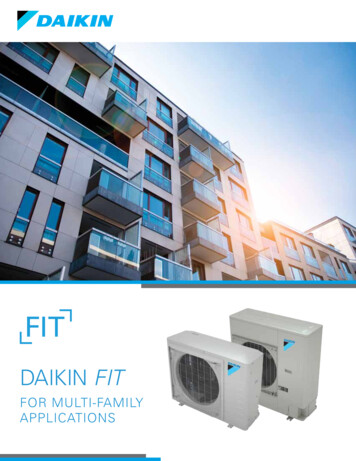
OVERVIEWDDC Controller DimensionsInput:24VAC Class 2Max. Amb. Temp:o60 85 COMMLOO"R"LOOP WIRE"T"“R” TO “R”,“T”TO “T”"SH“SHLD” TO “SHLD”OOE377-26B-00001BINARBINARY INPUTS (24V)BI1BI1: EMERGENCY SHUTDOWNBI2BI2: FAN PROVING SWITCHBI3BI3: COMP PRESSURE SW 1BI4BI4: COMP PRESSURE SW 2BI5BI5: REMOTE START/STOPBI6BI6: LOAD SHEDDINGBI7BI7: CLOGGED FILTER SWITCHBI8BI8: DEFROST SWITCH (ES)ANANALOG 7AI7:AI8AI8:BINARY OUTPUTS24V RLY1: COM1COMP1/STG1: RLY1COMP2/STG2: RLY224V RLY2: COM2BLOWER STG2: RLY4HEAT STG1: RLY5HEAT STG2: RLY6COND FAN: RLY7REV. VALVE(S): RLY824V RLY: COM3-8WaWattMaster Label#S#SW000067Rev.: 1G24V RLY: COM3-82424 VAC POWERONLYWARNING!POLAPOLARITY MUSTBEBE OBSERVEDOR THECCONTROLLERWILL BEDAMAGEDGNDRELAY CONTACTRATING IS 1 AMPMAX @ 24 VACBLOWER STG1: RLY3SUPPLY AIR TEMPOUTDOOR AIR TEMPECONOMIZER FEEDBACKOUTDOOR AIR HUMIDITYCO2 SENSORSPACE TEMPSPACE SLIDE ADJUSTSPACE HUMIDITY 24 VACPCBCG100ANALOG OUTPUTSECONOMIZER DAMPER: AO1MOD HGRH: AO2EXHAUST FAN (SSR): AO3ALARM (SSR): AO4E-BUSEXPANSIONE-BUSEXPANSIONUSBFigure 1: DAIKIN DDC Controller Dimensions12DAIKIN DDC Controller Technical Guide
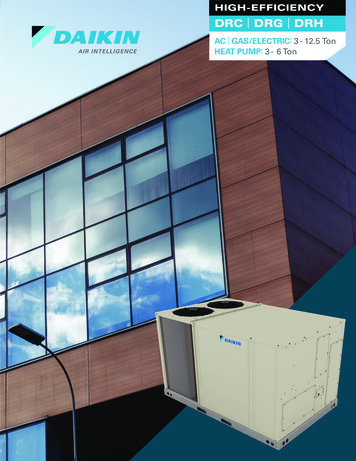
OVERVIEWController ComponentsRS-485CommunicationsDriver ChipDDCCONTROLLERALARMLEDCommunicationWire TerminalsOn-Board 5 COMMLOO"R"LOOP WIRE"T"“R” TO “R”,“T”TO “T”"SH“SHLD” TO “SHLD”OOE377-26B-00001Analog InputTerminalsUPMENUBinary InputTerminalsBinary InputLED - Typ. of 8Relay OutputTerminalsALARMBINARBINARY INPUTS (24V)BI1BI1: EMERGENCY SHUTDOWNBI2BI2: FAN PROVING SWITCHBI3BI3: COMP PRESSURE SW 1BI4BI4: COMP PRESSURE SW 2BI5BI5: REMOTE START/STOPBI6BI6: LOAD SHEDDINGBI7BI7: CLOGGED FILTER SWITCHBI8BI8: DEFROST SWITCH (ES)ANANALOG 7AI7:AI8AI8:BINARY OUTPUTS24V RLY1: COM1COMP1/STG1: RLY1COMP2/STG2: RLY2TroubleshootingLEDsDiagnosticBlink CodeLEDsPOWER LEDBACNET LED24V RLY2: COM2BLOWER STG2: RLY4HEAT STG1: RLY5BACnetMS/TPTerminal BlockHEAT STG2: RLY6COND FAN: RLY7REV. VALVE(S): RLY824V RLY: COM3-8WaWattMaster Label#S#SW000067Rev.: 1GAnalog OutputTerminals24V RLY: COM3-82424 VAC POWERONLYWARNING!POLAPOLARITY MUSTBEBE OBSERVEDOR THECCONTROLLERWILL BEDAMAGEDGNDRELAY CONTACTRATING IS 1 AMPMAX @ 24 VACBLOWER STG1: RLY3SUPPLY AIR TEMPOUTDOOR AIR TEMPECONOMIZER FEEDBACKOUTDOOR AIR HUMIDITYCO2 SENSORSPACE TEMPSPACE SLIDE ADJUSTSPACE HUMIDITY 24 VACPCBCG100Relay OutputLED - Typ. of 8ANALOG OUTPUTSECONOMIZER DAMPER: AO1MOD HGRH: AO2EXHAUST FAN (SSR): AO3ALARM (SSR): AO4E-BUSEXPANSIONE-BUSEXPANSIONUSB24 VACPower InputE-BUSE-BUSConnection ConnectionUSBConnectionFigure 2: DDC Controller ComponentsDAIKIN DDC Controller Technical Guide13
ZoneINSTALLATION & WIRINGImportant Wiring ConsiderationsGeneralZoneWARNING:Correct wiring of the DDC Controller is the most important factor inthe overall success of the controller installation process. In general,most DDC Controllers are factory installed and wired at the DAIKINfactory. Some of the following information pertains to field wiringand may not apply to your installation if it was pre-wired at thefactory. However, if troubleshooting of the controller is required, itis a good idea to be familiar with the system wiring, no matter if itwas factory or field wired.When using a single transformer to power morethan one controller or expansion module, thecorrect polarity must always be maintained between the boards. Failure to observe correctpolarity will result in damage to the DDCController.Please carefully read and apply the following information whenwiring the DDC Controller.1.All wiring is to be in accordance with local and nationalelectrical codes and specifications.2.All 24 VAC wiring must be connected so that all groundwires remain common. Failure to follow this procedurecan result in damage to the controller and connecteddevices.3.Minimum wire size for 24 VAC wiring should be18-gauge.4.Minimum wire size for all sensors should be 24-gauge.Some sensors require 2-conductor wire and some require3-or 4-conductor wire.Considerations5.Minimum wire size for 24 VAC thermostat wiringshould be 22 gauge.The DDC Controller must be connected to a 24 VAC power sourceof the proper size for the calculated VA load requirements. Alltransformer sizing should be based on the VA rating listed in Table 1.6.Be sure that all wiring connections are properly insertedand tightened into the terminal blocks. Do not allowwire strands to stick out and touch adjoining terminalswhich could potentially cause a short circuit.7.When communication wiring is to be used to interconnect DDC Controllers together or to connect to othercommunication devices, all wiring must be plenumrated, minimum 18-gauge, 2-conductor, twisted pair withshield.8.Before applying power to the DDC Controller,be sure to recheck all wiring connections andterminations thoroughly.Controller MountingSee Table 1 for a list of the required operating conditions for theDDC Controller.VA -00001DDC ControllerTemperatureControlDeviceThe DDC Controller
IP Module Kit OE415-02-G / 0130L00122 MiniLink PD 5 OE364-23-G / 0130L00125 Outdoor Air Humidity Sensor OE265-13-G / 0130L00106 Outdoor Air Temperature Sensor OE250-G / 0130L00108 PT-Link II LON-3-G OE368-23-LON-3-G / 0130L00124 Space Humidity Sensor OE265-11-G / 0130L00129 Standard Room Sensor - W/ Override & Slide Adjust OE213-G / 0130L00107