Transcription
THE ZEEMAN EFFECTREFERENCESMelissinos, Experiments in Modern PhysicsEisberg & Resnick, Quantum Physics of Atoms, Molecules, Solids, Nuclei and ParticlesKuhn, Atomic SpectraINTRODUCTIONIt is well known that an atom can be characterized by a unique set of discrete energystates. When excited through heating or electron bombardment in a discharge tube, theatom makes transitions between these quantized energy states and emits light. The emittedlight forms a discrete spectrum, reflecting the quantized nature of the energy states orenergy levels. In the presence of a magnetic field, these energy levels can shift. This effectis known as the Zeeman effect. The origin of Zeeman effect is the following. In an atomicenergy state, an electron orbits around the nucleus of the atom and has a magnetic dipolemoment associated with its angular momentum. In a magnetic field, it acquires anadditional energy just as a bar magnet does and consequently the original energy level isshifted. The energy shift may be positive, zero, or even negative, depending on the anglebetween the electron magnetic dipole moment and the field.Due to Zeeman effect, some degenerate energy levels will split into several nondegenerate energy levels with different energies. This allows for new transitions which canbe observed as new spectral lines in the atomic spectrum. In this experiment we will studyZeeman effect in neon and mercury for which the theory of Zeeman effect is somewhatmore tractable.Non-relativistic quantum theory accounts for only one type of angular momentumcalled orbital angular momentum. The Hamiltonian for an electron with angular momentum!! !!l has an additional term µBl ·H when a weak uniform magnetic field H is turned on. µ Bis a constant called the Bohr magneton. First order perturbation theory tells us that energylevels are shifted by"E µB Ml H[1]!where Ml is the quantum number for the component of l along the field. If an atom hadonly a single electron and the electron had only "orbital" angular momentum, then Eq. 1would represent the Zeeman shift.2-AZE-1
But electrons also have a different type of angular momentum called intrinsic spin!angular momentum, s . Spin emerges naturally only in relativistic quantum theories, but it! !can be shown that inserting a term gs µBs ·H (where gs # 2) into the non-relativisticHamiltonian gives the correct behavior of spin in a weak field. The first-order perturbationtheory gives a corresponding energy shift of"E µB gs Ms H[2]The shift is analogous to that due to orbital angular momentum, except for the constantfactor of gs . The energy shift for a particular state depends only on Ms (Ml for the orbitalcase) for that state. If an atom had only a single electron and the electron had only"intrinsic spin" angular momentum, then Eq. 2 would represent the Zeeman shift.Atoms typically have many electrons and are characterized by a total angular!momentum J which is the sum of all spin and orbital angular momenta. Though morecomplicated now, the energy shift is usually expressed in a similar looking form to Eqs. 1and 2."E µB g MJ H[3]The important difference is that g depends on the particular state of interest, as does MJ .By observing the spectra of neon and mercury we will be able to experimentallydetermine the g-factors for certain states. The values will be compared to the theoretical(Landé) g-factors, derived in the following sectionTHEORYA.Atomic States in Zero Field!!Each of the n electrons in an atom has orbital l i and spin s i angular momentum.The sum of all these is the total angular momentum of the atom (ignoring the nucleus).!!!J L S!n!L %l i[4][5]i 1!nS !%s ii 12-AZE-2[6]
NOTE:The convention used here is that angularmomentum operators are dimensionless.!! !For example l r &p /h.NOTE:Operators are shown in boldface.NOTE:Gaussian units are used.The atomic Hamiltonian in no field will be labeled H 0 . In the absence of external torques!!on the atom, the total angular momentum J is conserved (i.e. J commutes with H 0 ) and!energy eigenstates can be constructed which are also eigenstates of J 2 and Jz, where thedirection chosen for the z-axis is arbitrary. Each eigenstate can be labeled by quantumnumbers J and MJ , where! JMJ J2 JMJ J(J 1)and JM J Jz JMJ MJ[7]In principal there are terms in the Hamiltonian that represent interactions betweenthe individual angular momenta of the electrons. As a result, the individual angular!!momenta, as well as L and S , need not be conserved (i.e. need not commute with H 0 ).However, these interactions are small effects in many atoms. We will employ the usualapproximation, called L-S coupling (or Russel-Saunders coupling), which assumes that the!individual orbital angular momenta couple to produce a net orbital angular momentum Lwhich has a constant magnitude, but non-constant direction. Similarly the individual spins!form a net spin S which also has a constant magnitude. (This approximation is found tobreak down for large Z atoms.) Within this approximation, each eigenstate can beconstructed with the form JLSMJ with energy E0 (JLS) degenerate in MJ , where! JLSMJ L 2 JLSMJ L(L 1)!and JMJ S2 JMJ S(S 1)[8]Note that these states are not eigenstates of S z or Lz.B.Atomic States in Non-Zero Field - Zeeman EffectNow we will outline how Eq. 3 for the Zeeman energy shift can be derived. Withinthe L-S coupling model, the atomic Hamiltonian in a weak, uniform magnetic field is!!!H H 0 µB(L gs S )·H[9]where µB is called the Bohr magneton. It is usually most convenient to choose the z-axis!so that H H z , and we will do so in the discussion that follows. First order perturbationtheory gives energy shifts2-AZE-3
"E(JLSMJ ) µB JLSMJ Lz gs S z JLSMJ H[10]If the new term in the Hamiltonian (Eq. 9) were simply proportional to Jz Lz S z ratherthan Lz gs S z, then the energy shift would be simple and exactly analogous to Eq. 1. Thatis not the case however. The matrix elements in Eq 10 cannot be easily evaluated in theirpresent form since the states are not eigenstates of Lz and S z. However, it can be shownthat!!! JLSMJ L gs S JLSMJ JLSMJ g(JLS) J JLSMJ [11](using the Wigner-Eckart theorem for example), where g(JLS) is the Landé g-factor for a(JLS) state. With this simplification"E(JLSMJ ) µB g(JLS) JLSMJ Jz JLSMJ H µ B g(JLS) MJ H[12]As a result, each state has energyE(JLSMJ ) E0(JLS) µ B g(JLS) MJ H[13]which has the form of Eq. 3. The exact dependence of g on J, L, and S will be discussedbelow in section III-D.The effect of the Zeeman shifts can be seen experimentally. If a particular transitionin the absence of an applied field produces radiation at frequency '0 , then the frequency inthe presence of a field will be given byh' h'0 µB g(JLS) MJ H - µ B g(J'L'S') M J ' H[14]The primed symbols refer to the lower state and the unprimed to the upper state.C.Selection RulesConservation laws determine which transitions can occur ("allowed") and whichcan't ("forbidden"). The allowed transitions are specified by a set of conditions calledselection rules. The selection rules for these states are given below without derivation."l 1"L 0, 1"S 0"J 0, 1"MJ 0, 12-AZE-4[15][16][17][18][19]
NOTE:"MJ 1 transitions are called (transitions, while "MJ 0 transitions arecalled ) transitions.There are additional conditions as well: (1) ) transitions between levels both of which haveMJ 0 are forbidden if the sum of the J values of upper and lower states is even and (2) J 0 to J 0 transitions are forbidden.It should be noted that the selection rules above only apply to a type of transitioncalled an electric-dipole transition, which is the dominant type. Only "allowed" electricdipole transitions can occur. However, transitions which are "forbidden" by the electricdipole selection rules may still take place as other types of transitions. These events areless common and we will ignore them here.D.Landé g-factorA simple argument can be given for the value of g(JLS). Within the L-S coupling!!approximation, L and S are assumed to be individually conserved in magnitude but not!direction. Their components parallel to J must add to a constant value, but their!components perpendicular to J are constantly fluctuating. This means that the only part of!!L that contributes to the Zeeman effect is its component along J , namely! ! L·J !!J J 2 NOTE:[20] O stands for JLSMJ O JLSMJ .!Similarly, the only part of S that contributes is! ! S ·J !!J J 2 [21]Then the energy shift, Eq. 10 can be replaced by! !"E µBProblem 1! ! L·J g 0 S ·J ! J 2 MJ H[22]Show that Eq. 22 implies that the Landé g-factor isg(JLS) J(J 1) L(L 1)-S(S 1)J(J 1) S(S 1)-L(L 1) gs2J(J 1)2J(J 1)2-AZE-5[23]
In this experiment, certain transitions of neon and mercury atoms will be studied.This section deals with the application of L-S coupling to the particular states involved. Allof the spectral lines under consideration in this experiment correspond to allowedtransitions, as far as the selection rules are concerned.E.States of Neon (Ne) and Mercury (Hg)First consider neon. The 10 electrons in a neutral neon atom have a ground-stateconfiguration 1S2 2S2 2P6 . The n 1 and 2 shells are closed and as such the atom has S L J 0, making the ground state 1 S0 in spectroscopic notation.NOTE:For a given (JLS) state the notation is2S 1 X , where X S means L 0, X PJmeans L 1, X D means L 2, etc.The transitions to be studied in neon are between initial states with one electron excited to a3P level and final states with one electron excited to a 3S level (not transitions to the groundstate). These transitions are simple to study theoretically, because the neon atom can thenbe treated as a pair of particles — a hole in the n 2 shell and an electron in the n 3 shell.In this manner, all 9 unexcited electrons are treated as a single particle, a hole. If we labelthe excited electron as particle 1 and the hole as particle 2, the upper level for the transitions(2P5 3P1 ) has l1 1, s1 1/2, l2 1, and s2 1/2. The lower level for the transitions(2P5 3S1 ) has l1 0, s1 1/2, l2 1, and s2 1/2.Now consider mercury. The electrons have a ground-state configuration. 6S 2 . The transitions to be studied are between states with one excitedelectron. The initial and final configurations are 6S1 7S1 and 6S1 6P1 , respectively. Thesemercury transitions are similar to neon in that the angular momentum involves just twoparticles. If we label the excited electron as particle 1 and the other electron as particle 2,the upper level for the transitions (6S1 7S1 ) has l1 0, s1 1/2, l2 0, and s2 1/2. Thelower level for the transitions (6S1 6P1 ) has l1 1, s1 1/2, l2 0, and s2 1/2.1S2 2S2 2P6 3S2For these two-particle states the total orbital angular momentum (Eq. 5) is simply!!L l!1 l2[24]This is an operator equation. In terms of the eigenvalues it results in the triangle condition, l1 - l2 * L * l1 l22-AZE-6[25]
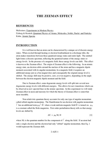
Thus, for the neon 2P5 3P1 configuration, the possible values of L are 0, 1, and 2, resultingin S, P, and D states. The 2P5 3S1 configuration can only lead to a P state. For mercury,the 6S1 7S1 configuration leads to an S state, while 6S1 6P1 leads to a P state.In L-S coupling, the total spin (Eq. 6) is!!S s!1 s[26]2with triangle rule, s1 - s2 * S * s1 s 2[27]Therefore, all states under consideration have S 0 or 1, giving rise to singlet and tripletstates.Finally, L and S are coupled to J with a final triangle rule L - S * J * L SE.[28]Transitions Studied in this ExperimentProblem 2For the neon green line at 585 nm, where the upper state is 1S0 (S 0, L 0,J 0) and the lower state is 1 P1 (S 0, L 1, J 1), show that the frequencyof the "MJ 1 transition is'0!1 '0 - g(J'L'S') µ BHz/h[29]while that of the "MJ -1 transition is,'0!-1 '0 g(J'L'S') µ BHz/h[30]Also, show that the "MJ 0 frequency is unaffected by the magnetic field.MJ01S0"M 1M J' 10-1"M -12-AZE-71P1
Fig. 1 Zeeman splitting of the neon 585-nm lineProblem 3For the neon red line at 603 nm, where the upper state is 3 P1 (S 1, L 1,J 1) and the lower state is 3 P1 (S 1, L 1, J 1), show that the frequenciesof the "MJ 1 transitions are'0!1 '0 - g(J'L'S') µ BHz/h'-1!0 '0 - g(JLS) µ BHz/h[31][32]while that of the "MJ -1 transitions are'1!0 '0 g(JLS) µ BHz/h'0! 1 '0 g(J'L'S') µ BHz/h[33][34]The frequencies of the "MJ 0 transitions are'1!1 '0 [g(JLS) - g(J'L'S')] µBHz/h'-1! 1 '0 - [g(JLS) - g(J'L'S')] µBHz/h[35][36]The '0!0 is absent since it is forbidden.MJ10-13P1"M 1M J' 10-1"M -13P1Fig. 2 Zeeman splitting of the neon 603-nm lineProblem 4Compute the predicted g-factors for all of the neon states analyzed above.Problem 5(OPTIONAL) For the mercury green line at 546 nm, where the upper stateis 3 S1 (L 0, S 1, J 1) and the lower state is 3 P2 , (L 1, S 1, J 2), showthat the possible "MJ 1 transitions are2-AZE-8
'1!2 '0 - [2g(J'L'S') - g(JLS)] µBHz/h'0!1 '0 - g(J'L'S') µ BHz/h'-1!0 '0 - g(JLS) µ BHz/h[37][38][39]while the "MJ -1 transitions are'1!0 '0 g(JLS) µ BHz/h'0! 1 '0 g(J'L'S') µ BHz/h'-1! 2 '0 [2g(J'L'S') - g(JLS)] µBHz/hMJ10-13S1[40][41][42]"M 1M J'210-1-2"M -13P2Fig. 3 Zeeman splitting of the mercury 546-nm lineF.Polarization of the Emitted LightWhen an atom undergoes a ) transition ("MJ 0), its angular momentum about thez-axis does not change. The atom satisfies this requirement by having its optically activeelectron oscillate along the z-axis, thereby giving rise to an electric field polarized in thisdirection.On the other hand, when the atom undergoes a ( transition ("MJ 1), its opticallyactive electron performs a rotary motion in the x-y plane in order that the photon emittedcarry angular momentum about the z-axis. The electric field then lies predominately in thex-y plane. Seen edge on, this constitutes a linear polarization perpendicular to the z-axis.Using a linear polarizer then one can separate these two types of transitions.2-AZE-9
EXPERIMENTObservetheZeemaneffectin the two lines of neon analyzedabove.Comparethe gfrom fringe matchingwith thosepredictedon the basisof L-S coupling.factorscalculatedNote that L-S couplingis an imperfectmodelfor neon. In particular,the g-factorofthe 3P1 stateof neonis poorly predicted.A bettercalculationby Shortley(PhysicalReview47,295 ( 1935))givesa valueof I .34. However,the remainingneonstatesunderconsiderationhave g-factorsnot very different from the Lande g-factorspredictedby L-Scoupling. Finally, measurethe g-factorsfor the 622 nm line in neon, and predict thequantumnumbersL, S, and J for the two statesinvolved in this transition.Mercury spectrum: get your TA or instructorto changethe light sourcefromneonto mefcury. DON'T ATTEMPT TO MAKE THIS CHANGE YOURSELF. THELIGHT SOURCESARE VERY DELICATEI Then observethe green 546 nm line andthe blue 436 nm line (bestobservedwith the blue glassfilter) in mercury. Compareyourg-f-actorswith thosepredictedby L-S coupling.A.ApparatusThe centralanalyticaldevicein this experimentis an etalon,which is a slabofquartz(thickness:d 6.029mm, index of refraction:n 1.46)havingthe two opposingsidesaccuratelyparallel.On thesesidesis depositeda reflectingmaterial.The etalonissteeltubeand shouldnot be removedfrom it. DO NOT TOUCHhousedin a stainlessTHE REFLECTINGSURFACESOF THE ETALON!m rrofs()lensetalon(b)(a)Fig.4 (a) Lighr parh through an etalon;(b) Fringepattern.2-AZE-lO
The etalon (Fig. 4a) generates a series of circular interference fringes as shown inFig. 4b. The location of these fringes is given by the condition1 -sin2 !m" 22ndn[43]where d is the etalon thickness, " is the wavelength in free space, n in the index ofrefraction of the etalon and m is an integer called the "order of interference". Eq. 43 can bederived from the geometry shown in Fig. 4a. Successive fringes differ in m by one, butthe center most fringe does not have an m of zero. Setting ! equal to zero in Eq. 43 definesthe smallest value of m, which is generally a large number.After the light leaves the etalon, it passes through a linear polarizer. There are infact two linear polarizers, one above the other, so that the upper half of the field of viewhas one polarization, the lower half the other. One should arrange the polarizer orientationso that the upper half of the field of view is polarized parallel to the z-axis, the lower half,perpendicular to it.For the neon green line at 585 nm, there will be one # transition which (accordingto Eq. 3) will be unaffected by the magnetic field. Thus in the upper half of the field ofview the fringe pattern will not change as the magnetic field is applied. Also there are two transitions, one of which, according to Eq. 29, decreases in frequency as the magneticfield is increased. The other, according to Eq. 30, increases in frequency. Now atransition that decreases in frequency must increase in wavelength, and as seen in Eq. 43must increase in angle !. That is, it moves outward in the fringe pattern. A transition thatincreases in frequency moves inward in the fringe pattern.Therefore, a single fringe of the neon green line must be unchanged in the upperhalf of the field of view, but split in two in the lower half. The right-hand part of thefringe, where it crosses the horizontal axis, must look as shown in Fig. 5.Fig. 5 Split fringe pattern. The arrows indicate the direction the fringemoves as the magnetic field increases.2-AZE-11
Problem 6Sketchthe fringe patternthat a singlefringe breaksinto for the neon 603nm line. Then sketchthe fringe pattem for the neon 640-nm line(tD. -" Pr) andfor the mercury 546 nm line.Turning backto the neongreenline,if onefringe componentmovesoutwardandthe othermovesinward,therewill be a field at which the outwardmovingcomponentofonefringe will exactlyoverlapthe inward-movingfringe from the next order outwards. Itis this magneticfield that is to be measured.at the sameangle0, andWhenan exactoverlapoccurs,therearetwo frequenciesusingEq.43,thereforemlu (m 1) ),6lM)of the two fringesbeingoverlapped.where)"uand1"6arethe wavelengthsProblem7Showthatthe frequencydifferencebetweenthe two greenlinesof neonbeingoverlappedisc17;rJ .t,0 1l -sin20ml4sland that the exact overlap that occurs with the neon green line gives mAv 2g(J'L,5,)1tsHzlhct46lg(J'L'S')can beF,q.46can be solvedfor g(J'L'S').OnceH, hasbeenmeasured,calculated.The neonline at 603 nm hasg(J'L'S')almostequalto g(JLS),with g(J'L'S')the o linesarenot resolveddueto the broadeningcausedbysfightly larger. Furthermore,the Dopplereffect,coupledwith thefact thatthe g-factorsarealmostequal. However,amatchingof the o lines of adjacentorderscan be doneas before: the matchoccurswhenthe overlappedline is the narrowest.But in this case,the outermostline of one orderismatchingthe innermostline of the adjacentorder. Hence,the matchingcondition,an a lo gousto E q.46 is/znHrc ,Zzn-,Av tg(JLS) g(J'L'S') ffgivesawhereH1 is the magneticfield at which the matchingoccurred.This eQuationrelationbetweeng(JLS)and g(J'L'S').2-AZE-12l47l
Anotherrelationcan be obtainedby increasingthe magneticfield until the n linesmatchtheo linesas well as possible.What this meansis that eachof the n linesmatchesthe averageof the o linesfrom the adjacentorders. At this magneticfield H2, one hasthematchingconditionu o Htc[3g(J ' L ' S ' ) - g ( J L S ) ] ' f f mt 4 8lThis equation,togetherwith Eq.47 , allows one to solvefor g(JLS) and g(J'L'S')separately.To carry out the experimentwith the greenmercury line at 546 nm, considerthefollowing:The greenline of mercuryat 546 nm hasfringesfor the s transitionsfringes,thethat vary widely in intensity.Of the threeoutward-movingintensitiesarein the ratio6:3:1movingfrom the insideout. That is, thevnd\-t- -2 transitions.with thev1brightestfringesareassociated-2Therearetwo very easilyseenoverlapspossiblewith this spectralline. The first is wherethe threefringesfrom one order exactly overlapthethreefringesfrom the adjacentorder,giving a patternof threevery distinctfringeswith almostthe sameintensity.Problem8Find the analogof Eq. 46 for this case.The secondoverlapthatis easyto recognizeis whenthe two brightfringes of one order (thoseof relativeintensity6 and 3) exactlyoverlapthe two bright fringes of the adjacentorder. Then theoverlappedfringeshaverelativeintensity9 while the left-overfringeon eachsidehasrelativeintensity1 andis dim enoughto hardlybeseen.Thus the patternthatis observedis a brightpair of overlappedfrinses.Problem9Find the analogof Eq. 46 for this case.From the magneticfield valuesat which thesetwo overlapsoccur,the valuesof g(JLS)and g(J'L'S')can be calculated.2-AZE-13
B.Apparatus NotesMagnet and power supplyBell gauss meter, model 4048Etalon telescopeNeon lamp on mounting stand, with power supply and variacMercury 202 lamp and power supplyMAGNET POWER SUPPLYThe magnet power supply has no air interlock. WHEN YOU TURN IT ON,CHECK THAT THE BALL RISES IN THE PLASTIC CYLINDER ON THE FRONT OFTHE SUPPLY! If it doesn't rise, turn off the unit and get help.GAUSS METERThe gauss meter has a delicate Hall effect probe. BE CAREFUL NOT TODAMAGE IT! Read the meter's instructions to see how to calibrate it. Place the probe inthe magnetic field close to the lamp, so as to minimize errors due to field inhomogeneities.NEON LAMPThe power supply operates at very high voltages. DON'T TAKE APART THESUPPLY OR THE LAMP HOLDER WITHOUT GETTING ASSISTANCE!To light the lamp, turn the variac to zero, throw the switch on and turn up the variacuntil the discharge starts. One wants the spectral lines to not be power broadened, so oneshould use as low a voltage as possible. However, the magnetic field disturbs the plasmain the lamp and often causes the lamp to go out as the field is increased. The remedy is toturn up the variac with the magnetic field on until the lamp lights.ETALON TELESCOPEInsert the appropriate filter in the holder. DO NOT TOUCH THE GLASS OF THEFILTER, BUT HOLD IT BY THE METAL PARTS ONLY! The filter holder has beenadjusted to the optimum angle – do not change it without consulting your TA or instructor.DO NOT DROP THE FILTER!2-AZE-14
Move the telescopefrom sideto sideto get the brightestpattern. If it is notpushor pull the pin stickingout of the bottomof the telescope.Thisverticallycentered,pin is attachedto the etalon,and allows one to adjustits positionwithout removingit fromthetelescope.Do not removethe etalonfrom the telescopewithout help. DON'T TOUCH THEMIRRORED SURFACESOF THE ETALON UNDER ANY CIRCUMSTANCES!Undernormaloperationof the experiment,the etalonneednot have any adjustmentbeyondpushingor pulling the pin at the bottom.If the fringe patternis not horizontallycentered,adjustthe knurled screwat the farendof the telescope.Checkthat the polarizeris insertedwith a horizontalarrow and a veftical downpointingarrowfacingthe viewer. This causesthe polarizerto deliverthe linearpolarizationsabove.discussedMERCURY 202 LAMP'I'o carry out observationson mercury,get the TA or instructorto changelampsis nofor you. The Hg202lamp is very fragileandcannotbe replaced(themanufacturerlongerin business).The lamp powersupplyshouldbe operatedas follows:.Setthe intensitycontrolto 60. Positionthe probeof an oscilloscopecloseto the coil in the lamp holder. Don'tconnectthe probeto anything- a pickupsignalis desired.Adjust the probepositionuntil an rf signalfrom the coil is observed. Adjust the positionof the tuning plungeron the lamp holder until the rf signalis maximized.on the oscilloscope.Wait until the lamp Iights. This cantake 1 to 5 minutes.If the lamp doesnotfrom the TA, instructor,or Johnlight within 5 minutes,get assistanceMcGrath. Adjust the tuningplungerfor maximumbrightness.The Hg20zlamp is madeof quartz,which is transparentin the ultraviolet,soconsiderableultravioletradiationis emitted,sincemercuryhasa strongline at 254 nm.THIS RADIATION CAN DAMAGE YOUR EYES, SO NEVER LOOK AT THE LAMPtheseEXCEPTTHROUGH A PIECE OF GLASS OR PLASTIC! If you wear eyeglasses,2-AZE- '
will give protection. Likewise, the glass lens in the eyepiece of the etalon telescope willalso protect you.The filters for this line are colored glass. Use both greenish filters together.atomic light sourcemagnetnarrow-band filteretalonobjective lenstwo polarizers at 90 eyepiece lensFig. 6 Top view of optical system.2-AZE-16
2-AZE-2 But electrons also have a different type of angular momentum called intrinsic spin angular momentum, s!. Spin emerges naturally only in relativistic quantum theories, but it can be shown that inserting a term g sµ Bs! ·H! (where g s # 2) into the non-relativistic Hamiltonian gives the correct behavior of spin in a weak field.