Transcription
Journal of Theoretical and Applied Information Technology20th January 2013. Vol. 47 No.2 2005 - 2013 JATIT & LLS. All rights reserved.ISSN: 1992-8645www.jatit.orgE-ISSN: 1817-3195DYNAMIC SIMULATION OF SPIRAL BEVEL GEAR BASEDON SOLIDWORKS AND ADAMS11JIHUI LIANG, 2LILI XINSchool of Automobile and Traffic, Shenyang LIGONG University, Shenyang 110159, Liaoning, China2College of Engineering, Shenyang Agricultural University, Shenyang 110866, Liaoning, ChinaABSTRACTSpiral bevel gears are one of basic mechanical units to transmit motion between concurrent axes. Thetransmission has quite a few merits, such as the big overlap ratio, the high loading capacity, the hightransmitting efficiency, the stability and the small noises, and they are widely used in automotive vehicle,planes, machine tools and all kinds of machines. Mechanical properties of spiral bevel gear have significantinfluence on the whole mechanical structure and play an important role in the system optimization, strengthcheck, fault diagnosis and fault prediction, and gear tooth meshing-dynamic load is an important issue inthe gear research field. Three-dimensional models of spiral bevel gears are created by SOLIDWORKS andthen converted to ADAMS by means of data exchange interface between SOLIDWORKS and ADAMS. Bythe contact algorithm theory of multi-body dynamics and ADAMS, the dynamic simulation of the spiralbevel gears mesh is specified. The curves of angular speed, torque and meshing force on the spiral bevelgears are obtained by simulation calculation, which provide references to research on dynamiccharacteristics of gear driving device.Keywords: Spiral Bevel Gear, ADAMS, Gear Meshing, Dynamics Simulation1.INTRODUCTIONSpiral bevel gear is the most important industrialmechanical part. Its main feature is that the axis ofdrive gear and that of driven gear would intersectvertically here. Due to the influence of overlappingof gear end-face, more than two pairs of gears meshat the same time. Thus it could bear much loading.Moreover, its teeth do not mesh on the full length.Instead of that, one end of the teeth would steertowards the other end steadily, so the gear boaststhe advantages of smooth works, little noise andvibration facilitating the fact that the gear could beused in cars, tractors, machine tools and otherdynamic and motion-transmission devices. Itsmechanical behavior and working performance playan important role in the whole machine.It is essential for reliability design, checkingcalculation and fault diagnosis of gear system toknow how to have a good grasp of mechanicalproperties and movement characteristics of geartransmission, [1, 2, 3] introduce the detection ofmeshing force in gear meshing process. It is verydifficult to detect the interference condition of gearprofile, the force of gear surface and gear impactforce. [4, 5, 6] discuss the influence of vibration,noise, dynamical load, big stress and distortioncaused by high-speed and heavy-duty on the safetyand stability of the machine. It is instant to carry onthe study on the gear transmission system with highproperty.ADAMS developed by American MechanicalDynamics Inc Company is one of famous virtualprototype analytic software with powerful dynamicsimulation ability and post-processing function, andanalysis in statics, kinematics, and dynamics can beapplied easily. For shortcoming of geometricmodeling of ADAMS, SOLIDWORKS operationplatform is used to build 3D solid model of spiralbevel gear and realize virtual assembling of gear.With the help of ADAMS data exchange interface,geometric data generated in SOLIDWORKS systemis introduced into ADAMS/Vieiv2010 module andthen dynamic simulation of gear transmission isbuilt. Through simulation, the study on speed andchanges of meshing force in dynamic meshingprocess of spiral bevel gear could be used asreference for improvement and optimization of theparameter design of bevel gear [7, 8]. At the sametime it would serve as reliable basis for furtherstrength check and fatigue analysis of transmissionsystem. Section 2 mainly introduces the building ofspiral bevel gear model. Building dynamic moduleis analyzed in section 3 which mainly includes thechoices of contacting forces, tooth contactingtheory and contacting parameters. Section 4discusses the result and analysis of simulation, andsection 5 summarizes and concludes the paper.755
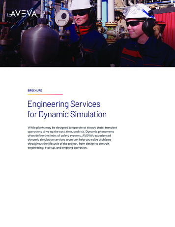
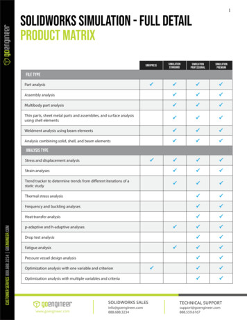
Journal of Theoretical and Applied Information Technology20th January 2013. Vol. 47 No.2 2005 - 2013 JATIT & LLS. All rights reserved.ISSN: 1992-86452.www.jatit.orgMODELING OF SPIRAL BEVEL GEAR3.Plug-in GearTrax of SOLIDWORKS softwarecould help to finish precise modeling of spiral bevelgear [9, 10]. After-assembling gear is just as that inFigure1. The pair of bevel gear belongs to driveaxle and the small bevel gear is drive gear withtwo-way operation and loading in smooth. Themaximum power of transmission of the gear systemis 140KW. The transmission ratio is 6.143. The lifeexpectancy is 10 years. Pinion is made of20CrMnTi with carburization and quenchingtreatment. Its surface hardness is 54 62 HRC.Large gear is made of 20CrMnTi with carburizationand quenching treatment. Its tooth face hardness is52 58 HRC . Parameters of spiral bevel gear are inTable 1.E-ISSN: 1817-3195BUILDING DYNAMIC MODULE3.1 The Choices of Contacting ForcesIn ADAMS, there are two types of contactingforces. One is contacting force based on Impactfunction and the other is based on Restitutionfunction. Impact uses stiffness coefficient anddamping coefficient to calculate contacting forcebut Restitution uses coefficient of restitution. In thearticle, Impact function is employed. And the basicform is Impact ( s, n, s0 , K 0 , j , C0 , d ) : s is actualdistance between objectives in the contactingprocess; n is the relative rotation speed ofobjectives when the two contact ; s0 is initialdisplacement value of contacting force excitation;K 0 is stiffness coefficient; j is contacting forceindex; C0 is damping coefficient ; d is inertiacenter distance of two contacting objectives. Thefunction takes comprehensive consideration ofmany factors in gear incentive, so it is a prettyprecise method of stimulation. Mathematicalcalculation method of impact function is:max(0 ,K 0 ( s0 s ) j C0 n STEP ( s,s0 d,1,s0 ,0))(1)STEP is a haversine step function.Figure 1: Three-Dimensional Models Of Spiral BevelGearsWhen s0 s 0 , impact function value is zeroand two gears do not contact.When s0 s 0 , two gears contact.The value of contacting force is relevant tostiffness coefficient K 0 , deformation s0 s ,contacting force index j and damping coefficientTable 1: The Proper Geometric Parameters Of SpiralBevel GearsParametersDriving gearDriven gearTooth numberEnd module /mmPressure angle /( )Face angle/( )Root angle /( )Breadth of tooth /mmTooth addendum /mmTooth dedendum /mmNodal bevel angle /( )Nodal bevel distance/mmHelix angle /( )Shaft angle /( 659.3427718035903590Change the after-assembling bevel gear moduleinto file format parasolid in SOLIDWORKS andintroduce CAD geometric module by exchangemodule in ADAMS.C0 . Figure 2 is impact force model of ADAMS,when the distance between I and J decreases toinitial displacement value ( s0 ), body I and Jbegin to collide. Collision force is made of elasticforce (rigid force) and damping force (viscousforce), and rigid force is proportional to K 0 andinversely proportional to penetration, which is thepenetration function about free length range of Iand J . Damping force is the function of penetrationvelocity, and its direction is to the oppositemovement direction. Impact force is related tostiffness coefficient ( K 0 ), contacting force index (j),damping coefficient ( C0 ) and inertia centerdistance of two contacting objectives ( d ). K 0depends on material and structure shape of theimpact bodies.756
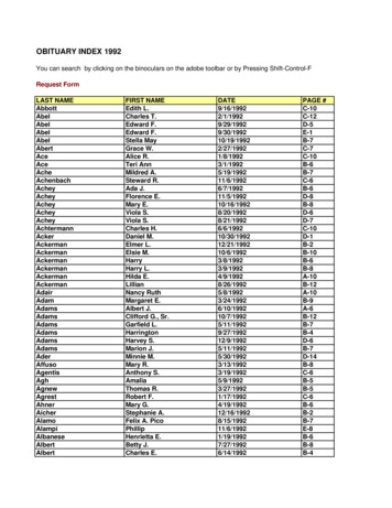
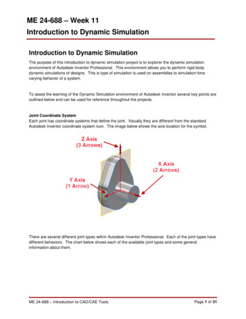
Journal of Theoretical and Applied Information Technology20th January 2013. Vol. 47 No.2 2005 - 2013 JATIT & LLS. All rights reserved.ISSN: 1992-8645www.jatit.orgE-ISSN: 1817-3195Referring to empirical value, contacting index j is2.2; damping coefficient c is 100N s-1; deepfriction and lubrication d is 0.1 mm. To get a realsituation of bevel gear meshing, gear adopts frictionand lubrication, while static friction coefficient is0.5 and dynamic friction coefficient is 0.3.Figure 2: Impact Force Model Of ADAMS3.2 The Choices of Tooth Contacting Theory andContacting ParametersImpact force of teeth contact can be the same tocollision of two variable camber radius cylinders.The problem can be solved in Hertz static elasticcontacting theory [11].According to Hertz contacting theory in whichcontacting area is round:1δ a29P 2 3 ()R16 RE 2(2)3.3 Restriction Imposition of Virtual PrototypeModuleBased on virtual prototype module in the article,add two rotating pairs and a contacting pair to bevelgear. Pinion is set to be driven gear as in Figure 3.Constant speed drive of driving wheel is 900 /s(150r/min). Constant loading torque of motor wheelis 15713000N mm. To prevent loading from drasticchanges, use STEP function to enable the gentleloading imposition in 0.1 second; That is(isSTEP ( time, 0, 0, 0.1, 15713000 )timeindependent variable). Loading torque imposed bySTEP function is in Figure 4. Dynamic simulationis with simulation time of 0.4 second and step sizeof 100[12].So the relation between contacting normal force3P and deformation δ is P K 0δ 2 . Stiffnesscoefficient K 0 depends on the materials andstructural shapes of contacting objectives.14 2R E3(3)111 R R1 R2(4)K0 Among which:Figure 3: Model Of Spiral Bevel Gears In ADAMSR1 and R2 are contacting radius of contactingobjects in the contacting point.1 (1 µ12 ) (1 µ 22 ) EE1E2(5)µ 1 and µ 2 are Poisson ratios of contactingobjectives. E1 and E2 are elastic modulus.Figure 4: Loading Torque On Driving GearSince materials are both 20CrMnTi, its Poissonratioµ 1 µ 2 0.25 , E1 E2 2.07 105N/mm2. Insert the figures into formula 5 andE 1.1 105 N/mm2 . As to formula 4,R 33.061 N/mm2. Insert E and R into formula 3,stiffnesscoefficientK 0 8.433 105N/mm2.4.RESULT AND ANALYSIS OFSIMULATIONFigure 5 is rotation speed curve of drive bevelgear, which shows rotation speed of input shaft isabout 900 /s (150r/min) and stays stable inaccordance with the inputted rotation speed of drivegear.757
Journal of Theoretical and Applied Information Technology20th January 2013. Vol. 47 No.2 2005 - 2013 JATIT & LLS. All rights reserved.ISSN: 1992-8645www.jatit.orgE-ISSN: 1817-3195Figure 7: Torque Of Driven GearFigure 5: Angular Speed Of Driving GearFigure 6 is rotation speed of driven bevel gear.The curve changes as time (t) changes. It shows thatfrom the initial stage of movement of driven bevelgear, under the co-influence of collision betweengears and gradually increasing torque on drivenbevel gear, rotation speed vary a lot. 0.05 secondslater, the gear movement goes smoothly whenrotation speed is about 200 /s in accordance withtheoretical rotation speed.Figure 8: The Curve Of Meshing Force5.Figure 6: Angular Speed Of Driven GearTorque curve of driven gear and teeth meshingforce curve are seen in Figure 7 and Figure 8.Referring to analysis of simulation, in 0 0.1second, since driven gear loading torque increases,the fluctuation range of driven gear torque is greaterand so does the range of meshing force. After 0.1second, the loading torque stays table and so doestorque which is about the same as loading torque(15713000N mm). All meshing forces go up anddown around a mean value(transmission load) incertain amplitude and their cycles and amplitudesare stable. That is periodic tooth mesh in and out.After 0.1 second, compare mean value of meshingforce with the theoretical calculation value and theyare almost the same which verifies the correctnessof simulation.CONCLUSIONSThe precise modeling of spiral bevel gear isbased on SOLIDWORKS software. Throughseamless interface program of SOLIDWORKS andADAMS, virtual prototype of gear meshingparameterization under ADAMS is realized;introduce Hertz contacting theory into simulationmodule and impose contacting force activelybetween main reducer and driven gear. The result isin accordance with theoretical calculating results,which verifies the feasibility of modeling design ofcombination of SOLIDWORKS and ADAMSsoftware and dynamics simulation. The result ofsimulation further verifies that stiffness excitationand meshing impulse excitation could producecyclical fluctuation. The method makes up for thedeficiency of modeling of mechanical parts withcomplicated and accurate positioning; at the sametime, it could serve as reliable basis for strengthcheck, optimization, vibration and noise analysis ofspiral bevel gear transmission system and othergear transmission system, of important engineeringapplication value.ACKNOWLEDGEMENTSThis work was supported by the National NaturalScience Foundation of China under GrantNo.51105259.758
Journal of Theoretical and Applied Information Technology20th January 2013. Vol. 47 No.2 2005 - 2013 JATIT & LLS. All rights reserved.ISSN: 1992-8645[2][3][4][5][6][7][8][9]E-ISSN: 1817-3195Zhenyun Duan, Houjun Chen, Zhilan Ju, JianLiu, “Mathematical model and manufactureprogramming of loxodromic-type normalYongjun Wu, Jianjun Wang, Qinkai Han,circular-arc spiral bevel gear”, Frontiers of“Contact finite element method for dynamicMechanicalEngineering, Vol. 7, No. 3, 2012,meshing characteristics analysis of continuouspp.312-321.engaged gear drives”, Journal of MechanicalScience and Technology, Vol. 26, No. 6, 2012, [10] Faydor L. Litvin, Alfonso Fuentes, IgnacioGonzalez-Perez, Luca Carvenali, Kazumasapp. 1671-1685.Kawasaki, Robert F. Handschuh, “ModifiedA. Palermo, D. Mundo, R. Hadjit, W. Desmet,involute helical gears: computerized design,“Multibody element for spur and helical gearsimulation of meshing and stress analysis”,meshing based on detailed three-dimensionalComputer Methods in Applied Mechanics andcontact calculations”, Mechanism and MachineEngineering, Vol. 192, No. 33–34, 2003, pp.Theory, Vol. 62, 2013, pp. 13-30.3619-3655.A. Fernandez del Rincon, F. Viadero, M.[11]F.L.Litvin, I. Gonzalez-Perez, A. Fuentes, K.Iglesias, P. García, A. de-Juan, R. Sancibrian,Hayasaka,K. Yukishima, “Topology of“A model for the study of meshing stiffness inmodifiedsurfacesof involute helical gears withspur gear transmissions”, Mechanism andlinecontactdevelopedfor improvement ofMachine Theory, Vol. 61, 2013, pp. 30-58.bearing contact, reduction of transmission errors,Faydor L. Litvin, Qiming Lian, Alexander L.and stress analysis”, Mathematical andKapelevich, “ Asymmetric modified spur gearComputer Modelling, Vol. 42, No. 9-10, 2005,drives: reduction of noise, localization ofpp. 1063-1078.contact, simulation of meshing and stressanalysis”, Computer Methods in Applied [12] He Zhang, Lin Hua, Xinghui Han,“Computerized design and simulation ofMechanics and Engineering, Vol. 188, No. 1-3,meshing of modified double circular-arc helical2000, pp. 363-390.gears by tooth end relief with helix”,Faydor L. Litvin, Daniele Vecchiato, EugeneMechanism and Machine Theory, Vol. 45, No. 1,Gurovich, Alfonso Fuentes, Ignacio Gonzalez2010, pp. 46-64.Perez, Kenichi Hayasaka, Kenji Yukishima,“Computerized Developments in Design,Generation, Simulation of Meshing, and StressAnalysis of Gear Drives”, Meccanica, Vol. 40,No. 3, 2005, pp. 291-323.Jiandong Sun, Wenyu Fu, Hong Lei, E. Tian,Ziping Liu, “Rotational swashplate pulsecontinuously variable transmission based onhelical gear axial meshing transmission”,Chinese Journal of Mechanical Engineering,Vol. 25, No. 6, 2012, pp. 1138-1143.X. Hua, T. C. Lim, T. Peng, W. E. Wali, “Dynamic analysis of spiral bevel geared rotorsystems applying finite elements and enhancedlumped parameters”, International Journal ofAutomotive Technology, Vol. 13, No. 1, 2012,pp. 97-107.S. H. Suh, D. H. Jung, S. W. Lee, E. S. Lee,“Modelling,Implementation,andManufacturing of Spiral Bevel Gears withCrown”, The International Journal of AdvancedManufacturing Technology, Vol. 21, No. 10-11,2003, pp. 775-786.REFERENCES:[1]www.jatit.org759
ON SOLIDWORKS AND ADAMS . 1 JIHUI LIANG, 2LILI XIN 1 School of Automobile and Traffic, Shenyang LIGONG University,Shenyang 110159, Liaoning, China . 2 College of Engineering, Shenyang Agricultural University, Shenyang 110866, Liaoning, China . ABSTRACT . Spiral bevel gears are one of basic mechanical units to transmit motion between concurrent .