Transcription
KVM SwitchAP5201AP5202Installation andQuick Start
ContentsProduct Description and Inventory . . . . . . . . . . . . . . . . . . . . . . 1Overview . . . . . . . . . . . . . . . . . . . . . . . . . . . . . . . . . . . . . . . . . 1Inventory . . . . . . . . . . . . . . . . . . . . . . . . . . . . . . . . . . . . . . . . . 1Hardware requirements . . . . . . . . . . . . . . . . . . . . . . . . . . . . . . 1Additional documentation . . . . . . . . . . . . . . . . . . . . . . . . . . . . . 2Front panel (AP5202 shown) . . . . . . . . . . . . . . . . . . . . . . . . . . 3Rear panel (AP5202 shown) . . . . . . . . . . . . . . . . . . . . . . . . . . . 4How to Mount the KVM Switch . . . . . . . . . . . . . . . . . . . . . . . . . 5How to Install a Single KVM Switch . . . . . . . . . . . . . . . . . . . . . . 6Pre-installation . . . . . . . . . . . . . . . . . . . . . . . . . . . . . . . . . . . . . 6Single-station installation . . . . . . . . . . . . . . . . . . . . . . . . . . . . . 6How to Install Multiple KVM Switches . . . . . . . . . . . . . . . . . . . . 8Pre-installation . . . . . . . . . . . . . . . . . . . . . . . . . . . . . . . . . . . . . 8Serial connection . . . . . . . . . . . . . . . . . . . . . . . . . . . . . . . . . . . 8How to Apply Power . . . . . . . . . . . . . . . . . . . . . . . . . . . . . . . . 10Operation . . . . . . . . . . . . . . . . . . . . . . . . . . . . . . . . . . . . . . . . 11Hot Key mode . . . . . . . . . . . . . . . . . . . . . . . . . . . . . . . . . . . . . 11Selecting the active port . . . . . . . . . . . . . . . . . . . . . . . . . . . . . 11Hot Key summary table . . . . . . . . . . . . . . . . . . . . . . . . . . . . . . 12On Screen Display (OSD) operation . . . . . . . . . . . . . . . . . . . . . 12OSD Navigation . . . . . . . . . . . . . . . . . . . . . . . . . . . . . . . . . . . 13OSD functions . . . . . . . . . . . . . . . . . . . . . . . . . . . . . . . . . . . . . 13Specifications . . . . . . . . . . . . . . . . . . . . . . . . . . . . . . . . . . . . . 14KVM Switch — Installation and Quick Starti
Product Description and InventoryOverviewThe KVM Switch can connect up to 32 switches to provide direct control of 16 computers or controlof up to 512 computers through serial connections, using only one keyboard, monitor, and mouse.InventoryQuantityItem1KVM SwitchAP5201 (8 port)AP5202 (16 port)1Configuration cable1L5-15 to IEC power cable2Brackets for a 19-inch enclosure1Installation Manual1KVM Switch Utility CD1Warranty cardHardware requirementsConsole. To use the KVM Switch you will need the following equipment: VGA, SVGA, or Multisync monitor capable of the highest resolution that you plan to use onany computer in the installation PS/2-style mouse PS/2-style keyboardComputer. To use and access the KVM Switch, your computer requires the following: VGA, SVGA or Multisync card 6-pin mini-DIN (PS/2 style) mouse port† Keyboard port‡:– 6-pin mini-DIN (PS/2 style) keyboard port with 5VDC on pin 4 and ground on pin 3, or– 5-pin DIN (AT style) keyboard port with 5VDC on pin 5 and ground on pin 4† The‡KVM Switch does not support serial mice. You cannot use serial-to-PS/2 adapters with the cables.If your computer uses an AT-style keyboard socket, purchase a PS/2-to-AT keyboard adapter to plug the cableinto the keyboard port on the computer.KVM Switch — Installation and Quick Start1
Product Description and InventoryCable. To use the KVM Switch, you need to connect the proper cables to the switch. The followingcables are available for purchase from APC:APC PartNumberCable type940-0247PS/2 cable – 6 ft940-0245PS/2 cable – 12 ft940-0246PS/2 cable – 25 ft940-0256USB cable – 6 ft940-0254USB cable – 12 ft940-0255USB cable – 25 ft940-0250SUN (13W3) cable – 6 ft940-0248SUN (13W3) cable – 12 ft940-0249SUN (13W3) cable – 25 ft940-0253SUN (VGA) cable – 6 ft940-0251SUN (VGA) cable – 12 ft940-0252SUN (VGA) cable – 25 ft940-0257Cascade cable for serial connectionIncorrect installation can cause improper functioning of the device or damage tohardware. Substandard cables can produce toxic fumes if a fire occurs.WarningAdditional documentationThe KVM Switch User’s Guide is available on the supplied CD and on the APC Web site(www.apc.com). The User’s Guide (.\doc\eng\usrguide.pdf) contains additional information aboutthe following topics related to the KVM Switch: On-Screen Display (OSD) and the menu-driven interface User accounts Hot-plugging Hot Key operation2KVM Switch — Installation and Quick Start
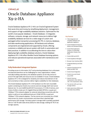
Product Description and InventoryFront panel (AP5202 shown) 12345678910111213141516 F/W UPGRADELOC ALNORMAL RECOVERRESETKVM Switch DISABLEREMOTEPOWERSTATION IDREMOTEREMOTE CONSOLEUPGRADEON LIN E SELECTED ItemDescription Port LEDsEach Port LED provides status information about a corresponding computerport. Each port has a left (Online) and right (Selected) LED pair. Thefollowing list describes the LED light indicators: A GREEN Online LED indicates the corresponding attached computer portis up and running. An ORANGE Selected LED indicates the corresponding attachedcomputer has the KVM focus. Under normal conditions, the LED is steady.When accessing its port under Auto Scan Mode, the LED flashes. Each time the KVM Switch begins to provide power, it performs a self-test.The Online and Selected LEDs blink once in succession during the selftest. Reset switchPress the recessed Reset switch with a thin object (the end of a paper clip orballpoint pen) to perform a system reset. Disable Remote buttonSwitches between local and remote access to the console. Remote consoleTo use a remote console, plug the serial cable into the RJ-45 connector. Whenboth a local and remote console are present, both can access the switch (notsimultaneously). Push the Disable Remote button to toggle between the remote and the localconsole. When the remote console is in control, you can only view through the localconsole. When the local console is in control, you can only view throughthe remote console. The Local and Remote LEDs indicate which console is currently in use. RJ-11 serial portThe firmware upgrade cable plugs into the RJ-11 connector and transfersfirmware upgrade data from the administrator's computer to the KVMSwitch. Power LEDIndicates when the KVM Switch is receiving power. Station ID LEDDisplays the station number of the KVM Switch. The station number is atwo-digit number indicating the switch's position in the cascading sequence. Firmware upgrade resetswitchThe reset switch is in NORMAL position during normal operation or whileperforming a firmware upgrade. If the firmware upgrade operation does notsucceed, slide the reset switch to the RECOVER position, turn the KVMSwitch off, and then restart the KVM Switch. Slide the reset switch back tothe NORMAL position, turn off the KVM Switch, and then restart the KVMSwitch.KVM Switch — Installation and Quick Start3
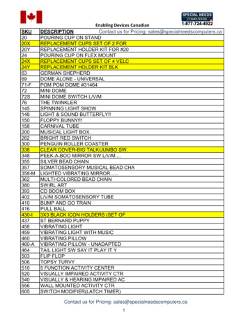
Product Description and InventoryRear panel (AP5202 shown) CONSOLEPOWERCHAIN IN N/A FOR ST No.1161514131211109CHAIN OUT87654321100-240V--1A, 50/60Hz Item4 Description Power inlet3-pin, AC power inlet Power switchRocker-style switch for turning the switch on or off Mouse connectorConnects to a PS/2-style mouse Chain In portSerially connects one KVM Switch to another. (This port is not used forthe highest-level KVM Switch in a cascaded setup.) Computer connectionsMonitors connected computers Chain Out portSerially connects one KVM Switch to another Keyboard connectorConnects to a PS/2-style keyboard Monitor connectorConnects to a VGA, SVGA, or Multisync monitor capable of the highestresolution that you plan to use on any computer in the installationKVM Switch — Installation and Quick Start
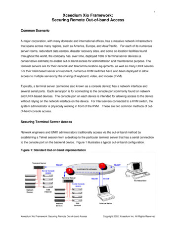
How to Mount the KVM SwitchMounting optionsYou can install the KVM Switch in the front or the rear of the rack or enclosure. To mount the KVMSwitch horizontally in a NetShelter or any other standard EIA-310 rack or enclosure:1. Attach the mounting brackets to the front or rear of the KVM Switch, using flat-head screws(provided).2. Insert caged nuts (provided with the rack) on the vertical mounting rails above a number at thestart of a U-space in your enclosure and below the same number at the lower end of theU–space.211U20193. Align the mounting holes on the brackets with the caged nuts you installed in step 2, and insertfour mounting screws (provided with the rack) to secure the brackets to the enclosure.KVM Switch — Installation and Quick Start5
How to Install a Single KVM SwitchPre-installationTurn off power to all devices that you plan to connect. To prevent damage to your equipment becauseof static-electric discharge, ground all devices on the installation.Consult your device manuals or contact the product’s customer support departmentfor safety and grounding instructions.WarningSingle-station installationIn a single-station installation, no additional KVM Switches are serially connected to the first switch.To install:1. Plug your keyboard, mouse, and monitor into the correct ports on the rear of the KVM Switch.CONSOLECHAIN INN/A FOR ST No.1POWER100-240V--1A, 50/60Hz6KVM Switch — Installation and Quick StartCHAIN OUT
How to Install a Single KVM Switch2. Use custom cable sets (see “Cable” on page 2) to connect any available computer port on therear of the KVM Switch to the Keyboard, Video, and Mouse ports of the computer you areinstalling.111093213. Plug the power cable into the port marked Power on the rear of the KVM Switch, and then plugthe power cable into an AC power source.4. Apply power to the computers.KVM Switch — Installation and Quick Start7
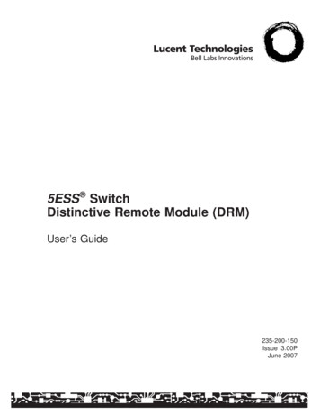
How to Install Multiple KVM SwitchesPre-installationTurn off power to all devices that you plan to connect. To prevent damage to your equipment becauseof static-electric discharge, ground all devices on the installation.Consult your device manuals or contact the product’s customer support departmentfor safety and grounding instructions.WarningSerial connectionTo control additional computers, you can connect up to 31 KVM Switches from the first KVMSwitch. In a complete installation, you can control up to 512 computers from a single console.1. Turn off power to all devices that you plan to connect.2. Use a serial cable to connect the Chain Out port of the first KVM Switch to the Chain In portof the second KVM Switch. (i.e., first station Chain Out to second station Chain In, secondstation Chain Out to third station Chain In, etc.)Do not use the Chain In port of the first station. The Chain In port is the highestlevel parent in the chain.NoteCONSOLECHAIN INN/A FOR ST No.1POWERCHAIN OUT100-240V--1A, 50/60HzCONSOLECHAIN INN/A FOR ST No.1POWER100-240V--1A, 50/60HzCHAIN OUTCONSOLECHAIN INN/A FOR ST No.1POWER100-240V--1A, 50/60Hz8KVM Switch — Installation and Quick StartCHAIN OUT
How to Install Multiple KVM Switches3. Use custom cable sets (see “Cable” on page 2), to connect any available computer port on theKVM Switch installation to the Keyboard, Video, and Mouse ports of the computers you areinstalling.111093214. See “How to Apply Power” on page 10 to complete the multi-switch installation.KVM Switch — Installation and Quick Start9
How to Apply PowerTo apply power for a mutiple-switch system:1. Plug in the power cable for the first KVM station. Wait for the switch to discover and display itsstation ID on the Station ID LED. (The station ID for the first station is 01, the ID for thesecond station is 02, the ID for the third station is 03, and so on.)2. Plug in the power cables for each KVM Switch on the system in order of second station, thirdstation, and so on. In each case, wait for the station ID to be discovered and displayed on thecurrent KVM Switch before plugging in the next one.3. After all the KVM Switches are running, apply power to the computers.Powering off and restartingAlways follow this procedure after turning off the KVM Switch.1. Remove power from all connected computers.Unplug the power cord of any computer with the Keyboard Power On functionenabled; otherwise, the station continues to receive power from the computers.Note2. Wait 10 seconds, and then plug in the KVM Switch.3. Apply power to the computers only after the KVM Switch is running.If you shut down more then one station, apply power to the highest-numberedstation first, continuing down to the lowest-numbered station.Note10KVM Switch — Installation and Quick Start
OperationSelect ports using one of the following two methods: entering Hot Key combinations from thekeyboard or using the On-Screen Display (OSD).Hot Key modeTo activate or deactivate Hot Key mode, press NUM LOCK and the hyphen key at the same time.Release the hyphen key within ½ second. Otherwise Hot Key activation stops and hasno effect.NoteWhen Hot Key mode is active, the following changes occur: Caps Lock and Scroll Lock LEDs flash in succession. These stop flashing and revert to normalstatus after you exit Hot Key mode. The screen displays the words Hot Keys and all subsequent keyed-in Hot Key information. Ordinary keyboard and mouse function have no effect. You may only input Hot Key-compliantkeystrokes and mouse clicks.Press ESC to exit Hot Key mode.See the User’s Guide on the provided KVM Switch Utility CD for additionalinformation about Hot Key functions.See alsoSelecting the active portEach computer port is assigned a Port ID. Directly access any computer on the installation with a HotKey combination that specifies the Port ID of the connected computer’s port.To select the active port:1. Activate Hot Key mode by pressing NUM LOCK and the hyphen key at the same time.2. Enter the Port ID.NoteThe Port ID displays on the Command Line as you type each number. Forexample, enter 0305 to switch to Port 5 of the third KVM Switch on the chain.Use BACKSPACE to erase an incorrectly typed number.Press ENTER. The KVM Switch will focus on the designated computer and exit Hot Key mode.KVM Switch — Installation and Quick Start11
OperationHot Key summary tableThe following table summarizes Hot Key operations on the KVM Switch:ActionNUM LOCK hyphenDescriptionPort IDT number1–255ASwitches access to the computer corresponding to the Port ID.Sets the Auto Scan interval to a number of seconds from 1 to 255. Activates Auto Scan mode. To pause Auto Scan, press P or left-click the mouse. To resume Auto Scan, press any key or left-click the mouse.Activates Skip mode and skips from the current port to the precedingport.Activates Skip mode and skips from the current port to the next port.Activates Skip mode and skips from the current port to the last portof the previous KVM station.Activates Skip mode and skips from the current port to the first portof the next KVM station.BToggles the beeper on or off.On Screen Display (OSD) operationTo activate the OSD main menu:1. Press the pre-assigned hotkey, SCROLL LOCK, twice to access the login window.Optionally, you can assign the control key as the main menu hotkey. See the User’sGuide on the provided KVM Switch Utility CD for additional information.See also2. Do either of the following:– Enter a valid password in the password field, and press ENTER.– For a first-time OSD activation, or if the password has not been set, leave the password fieldblank, and press ENTER.The OSD main menu appears in Administrator mode. Administrator mode provides access to bothAdministrator and User functions and lets you set up operations (including future passwordauthorization).12KVM Switch — Installation and Quick Start
OperationOSD navigationUse any of the following methods to navigate the OSD main menu screen: To dismiss the main menu and deactivate the OSD, press ESC or click the X at the upper-righthand corner of the screen. To log off of the OSD, press F8 or click F8 LOUT at the top of the screen. To move up or down through the list one line at a time, press the up or down arrows key or clickthe up or down arrow symbols on the OSD’s right scroll bar. To move up or down through the list one screen at a time, press the PGUP or PGDN key or clickthe up or down arrow symbols on the OSD’s right scroll bar. To activate a port, double-click its name in the list or highlight the name, and press ENTER.Each action returns you to the menu.OSD functionsThe OSD provides a series of function keys to configure and control various computer operations.For example, you can switch to any port, scan selected ports, and limit the list of ports you want toview. You can also manage port names or make OSD setting adjustments.To access any OSD function do one of the following: Press the desired function key on your keyboard. Click a function key menu option located at the top of the main menu screen.A submenu appears that corresponds to your selected function key.Press ESC to return to the previous menu level.See the User’s Guide on the provided KVM Switch Utility CD for additionalinformation on the On Screen Display and its functions.See alsoKVM Switch — Installation and Quick Start13
SpecificationsElectricalPower supply100–240 V; 50 or 60 HzConnectorsConsole VGAConsole K/MCPU PortsSerial connectionRemote accessFirmware UpgradePowerHDB - 15F(2) pin mini DIN F (keyboard: purple; Mouse: green)(16) SPDB - 15FDB - 25 F, 1 DB - 25 MRJ-45RJ-113-pin AC power jackEmulationKeyboardMousePS/2PS/2Scan intervalUser specified: 1 to 255 secondsPower consumptionDC 9V, 8W (max)PhysicalSwitchesPowerFirmware recoverResetRemote accessRocker switchSlide switchSemi-recessed push-buttonLocking push-buttonLEDsOn-lineSelectedPowerStation ID16 (Green)16 (Orange)1 (Blue)2 7 segmentsVideo1920 1440, DDC2BHousingMetalWeight7.9 lb (3.56 kg)Dimensions (L W H)17 8.25 1.75 in (43.2 21 4.5 cm)Environmental14TemperatureOperatingStorage0 to 50º C (32º to 122º F)–20 to 60º C (–4º to 122º F)Humidity0–80% RHKVM Switch — Installation and Quick Start
Radio Frequency InterferenceWarningChanges or modifications to this unit notexpressly approved by the partyresponsible for compliance could void theuser’s authority to operate thisequipment.USA—FCCThis equipment has been tested and found to comply with the limits for aClass A digital device, pursuant to part 15 of the FCC Rules. These limits aredesigned to provide reasonable protection against harmful interference whenthe equipment is operated in a commercial environment. This equipmentgenerates, uses, and can radiate radio frequency energy and, if not installedand used in accordance with this user manual, may cause harmfulinterference to radio communications. Operation of this equipment in aresidential area is likely to cause harmful interference. The user will bear soleresponsibility for correcting such interference.Canada—ICESThis Class A digital apparatus complies with Canadian ICES-003.Cet appareil numérique de la classe A est conforme à la norme NMB-003 duCanada.Japan—VCCIThis is a Class A product based on the standard of the Voluntary ControlCouncil for Interference by Information Technology Equipment (VCCI). Ifthis equipment is used in a domestic environment, radio disturbance mayoccur, in which case, the user may be required to take corrective ��基づくクラス A �求されることがあります。aa
APC Worldwide Customer SupportCustomer support for this or any other APC product is available at no charge in any of the following ways: Visit the APC Web site to find answers to frequently asked questions (FAQs), to accessdocuments in the APC Knowledge Base, and to submit customer support requests.– www.apc.com (Corporate Headquarters)Connect to localized APC Web sites for specific countries, each of which provides customersupport information.– www.apc.com/support/Global support with FAQs, knowledge base, and e-support. Contact an APC Customer Support center by telephone or e-mail.– Regional centers:Direct InfraStruXure Customer SupportLine(1)(877)537-0607 (toll free)APC headquarters U.S., Canada(1)(800)800-4272 (toll free)Latin America(1)(401)789-5735 (USA)Europe, Middle East, Africa(353)(91)702000 (Ireland)Japan(0) 35434-2021Australia, New Zealand, South Pacificarea(61) (2) 9955 9366 (Australia)– Local, country-specific centers: go to www.apc.com/support/contact for contact information.Contact the APC representative or other distributor from whom you purchased your APC product forinformation on how to obtain local customer support.Entire contents copyright 2003 American Power Conversion. All rights reserved.Reproduction in whole or in part without permission is prohibited. APC, the APC logo, andNetShelter are trademarks of American Power Conversion Corporation and may beregistered in some jurisdictions. All other trademarks, product names, and corporate namesare the property of their respective owners and are used for informational purposes only.990-1744*990-1744*12/2003
To use and access the KVM Switch, your computer requires the following: VGA, SVGA or Multisync card 6-pin mini-DIN (PS/2 style) mouse port† Keyboard port‡: - 6-pin mini-DIN (PS/2 style) keyboard port with 5VDC on pin 4 and ground on pin 3, or - 5-pin DIN (AT style) keyboard port with 5VDC on pin 5 and ground on pin 4