Transcription
Parametric ModelingwithPro/ENGINEER Wildfire 5.0An Introduction to Pro/ENGINEER WILDFIRERandy H. ShihOregon Institute of TechnologySDCPUBLICATIONSSchroff Development Corporationwww.schroff.comBetter Textbooks. Lower Prices.
Parametric Modeling with Pro/ENGINEERChapter 1Parametric Modeling Fundamentals Create Simple Extruded Solid Models. Understand the Basic ParametricModeling Process. Create 2-D Sketches. Understand the "Shape before Size"approach. Use the Dynamic Viewing commands. Create and Modify ParametricDimensions.1-1
1-2Parametric Modeling with Pro/ENGINEERIntroductionThe feature-based parametric modeling technique enables the designer to incorporatethe original design intent into the construction of the model. The word parametric meansthe geometric definitions of the design, such as dimensions, can be varied at any time inthe design process. Parametric modeling is accomplished by identifying and creating thekey features of the design with the aid of computer software. The design variables,described in the sketches and features, can be used to quickly modify/update the design.In Pro/ENGINEER, the parametric part modeling process involves the following steps:1. Set up Units and Basic Datum Geometry.2. Determine the type of the base feature, the first solid feature, of the design.Note that Extrude, Revolve, or Sweep operations are the most commontypes of base features.3. Create a rough two-dimensional sketch of the basic shape of the base featureof the design.4. Apply/modify constraints and dimensions to the two-dimensional sketch.5. Transform the two-dimensional parametric sketch into a 3D feature.6. Add additional parametric features by identifying feature relations andcomplete the design.7. Perform analyses/simulations, such as finite element analysis (FEA) or cutterpath generation (CNC), on the computer model and refine the design asneeded.8. Document the design by creating the desired 2D/3D drawings.The approach of creating three-dimensional features using two-dimensional sketches isan effective way to construct solid models. Many designs are in fact the same shape inone direction. Computer input and output devices we use today are largely twodimensional in nature, which makes this modeling technique quite practical. This methodalso conforms to the design process that helps the designer with conceptual design alongwith the capability to capture the design intent. Most engineers and designers can relateto the experience of making rough sketches on restaurant napkins to convey conceptualdesign ideas. Note that Pro/ENGINEER provides many powerful modeling and designtools, and there are many different approaches to accomplish modeling tasks. The basicprinciple of feature-based modeling is to build models by adding simple features one ata time. In this chapter, a very simple solid model with extruded features is used tointroduce the general feature-based parametric modeling procedure.
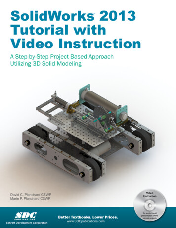
Parametric Modeling Fundamentals1-3The Adjuster designStarting Pro/ENGINEERHow to start Pro/ENGINEER depends on the type of workstation and the particularsoftware configuration you are using. With most Windows and UNIX systems, you mayselect Pro/ENGINEER on the Start menu or select the Pro/ENGINEER icon on thedesktop. Consult your instructor or technical support personnel if you have difficultystarting the software.1. Select the Pro/ENGINEER option on the Start menu or select thePro/ENGINEER icon on the desktop to start Pro/ENGINEER. ThePro/ENGINEER main window will appear on the screen.2. Click on the New icon, located in the Standardtoolbar as shown.
1-4Parametric Modeling with Pro/ENGINEER3. In the New dialog box, confirm the model’s Type is set to Part (Solid Subtype).4. Enter Adjuster as the part Name asshown in the figure.5. Turn off the Use default templateoption.6. Click on the OK button to accept thesettings.7. In the New File Options dialog box,select EMPTY in the option list tonot use any template file.8. Click on the OK button to accept thesettings and enter thePro/ENGINEER Part Modelingmode. Note that the part name, Adjuster, appears inthe title area of the main window and in theNavigator Model Tree window.
Parametric Modeling Fundamentals1-5Step 1: Units and Basic Datum Geometry Setups Units SetupWhen starting a new model, the first thing we should do is to choose the set of unitswe want to use.1. Use the left-mouse-button and select File inthe pull-down menu area.1. Pick File2. Use the left-mouse-button and selectProperties in the pull-down list as shown. Note that the Pro/ENGINEER menu system iscontext-sensitive, which means that the menuitems and icons of the non-applicable optionsare grayed out (temporarily disabled).2. Pick Properties3. Select the Change option that is to the left of the Units option in the ModelProperties window.
1-6Parametric Modeling with Pro/ENGINEER4. In the Units Manager – Systems of Unitsform, the Pro/ENGINEER default settingInch lbm Second is displayed. The set ofunits is stored with the model file when yousave. Pick Inch Pound Second (IPS) byclicking in the list window as shown.5. Click on the Set button to accept the selection.6. In the Changing Model Units dialog box,click on the OK button to accept the defaultoption to change of the units. Note that Pro/ENGINEER allows us tochange model units even after the model hasbeen constructed; we can change the unitsby (1) Convert dimensions or (2) Interpretdimensions.7. Click on the Close button to exit the Units Manager dialog box.8. Pick Close to exit the Model Properties window.
Parametric Modeling Fundamentals1-7 Adding the First Part Features – Datum Planes Pro/ENGINEER provides many powerful tools for model creation. In doing featurebased parametric modeling, it is a good practice to establish three reference planes tolocate the part in space. The reference planes can be used as location references infeature constructions. Move the cursor toward the right side of the main windowand click on the Datum Plane Tool icon as shown.Datum planes In the Navigator Model Tree window and the display area, three datum planesrepresented by three rectangles are displayed. Datum planes are infinite planes andthey are perpendicular to each other. We can consider these planes as XY, YZ, andZX planes of a Cartesian coordinate system.1. Notice in the model tree window, DTM3 is highlighted; clickthe model name, Adjuster.prt, in the navigator window todeselect DTM3.
1-8Parametric Modeling with Pro/ENGINEERStep 2: Determine/Setup the Base Solid Feature For the Adjuster design, we will create an extruded solid as the base feature.1. In the Feature Toolbars(toolbars aligned to theright edge of the mainwindow), select theExtrude Tool icon asshown. The Feature Option Dashboard, which contains applicable construction options, isdisplayed below the Standard toolbar of the Pro/ENGINEER main window.2. On your own, move the cursor over the icons andread the descriptions of the different optionsavailable. Note that the default extrude option is setto Extrude as Solid.3. Click the Placement Option andchoose Define to begin creating anew internal sketch.
Parametric Modeling Fundamentals1-9Sketching plane – It is an XY CRT, but an XYZ WorldDesign modeling software is becoming morepowerful and user friendly, yet the system stilldoes only what the user tells it to do. Whenusing a geometric modeler, we therefore needto have a good understanding of what itsinherent limitations are. We should also havea good understanding of what we want to doand what to expect, as the results are based onwhat is available.In most 3D geometric modelers, 3D objectsare located and defined in what is usuallycalled world space or global space. Althougha number of different coordinate systems canbe used to create and manipulate objects in a3D modeling system, the objects are typicallydefined and stored using the world space. Theworld space is usually a 3D Cartesiancoordinate system that the user cannotchange or manipulate.In most engineering designs, models can be very complex, and it would be tedious andconfusing if only the world coordinate system were available. Practical 3D modelingsystems allow the user to define Local Coordinate Systems (LCS) or User CoordinateSystems (UCS) relative to the world coordinate system. Once a local coordinate systemis defined, we can then create geometry in terms of this more convenient system.Although objects are created and stored in 3D space coordinates, most of the geometricentities can be referenced using 2D Cartesian coordinate systems. Typical input devicessuch as a mouse or digitizer are two-dimensional by nature; the movement of the inputdevice is interpreted by the system in a planar sense. The same limitation is true ofcommon output devices, such as CRT displays and plotters. The modeling softwareperforms a series of three-dimensional to two-dimensional transformations to correctlyproject 3D objects onto the 2D display plane.The Pro/ENGINEER sketching plane is a special construction approach that enables theplanar nature of the 2D input devices to be directly mapped into the 3D coordinatesystem. The sketching plane is a local coordinate system that can be aligned to anexisting face of a part, or a reference plane.Think of the sketching plane as the surface on which we can sketch the 2D sections of theparts. It is similar to a piece of paper, a white board, or a chalkboard that can be attachedto any planar surface. The first sketch we create is usually drawn on one of theestablished datum planes. Subsequent sketches/features can then be created on sketchingplanes that are aligned to existing planar faces of the solid part or datum planes.
1-10Parametric Modeling with Pro/ENGINEERDefining the Sketching Plane The sketching plane is a reference location where two-dimensional sketches arecreated. The sketching plane can be any planar part surface or datum plane. Note thatPro/ENGINEER uses a two-step approach in setting up the selection and alignment ofthe sketching plane. In the Section Placement window, theselection of the sketch plane and theorientation of the sketching plane areorganized into two groups as shown in thefigure. The Sketch Plane can be set to anysurfaces, including datum planes. TheSketch Orientation is set based on theselection of the Sketch plane.1. Notice the Plane option box in the Sketchwindow is activated, and the message“Select a plane or surface to define sketchplane.” is displayed in the message area.2. In the graphic area, select DTM2 by clickingon the text DTM2 as shown. Notice an arrow appears on the edge ofDTM2. The arrow direction indicates theviewing direction of the sketch plane. Theviewing direction can be reversed by clickingon the Flip button in the Sketch Orientationsection of the popup window.
Parametric Modeling Fundamentals1-11Defining the Orientation of the Sketching Plane Although we have selected the sketching plane, Pro/ENGINEER still needs additionalinformation to define the orientation of the sketch plane. Pro/ENGINEER expects usto choose a reference plane (any plane that is perpendicular to the selected sketchplane) and the orientation of the reference plane is relative to the computer screen. To define the orientation of the sketching plane, select the facingdirection of the reference plane with respect to the computer screen.The selected sketching plane,DTM2, will be aligned parallelto the 2D computer screen.We will orient the sketchingplane by setting the positiveside of DTM3 to face towardthe bottom edge of thecomputer screen.1. Notice the Reference option box in the SketchOrientation window is now activated. The message“Select a reference, such as surface, plane or edgeto define view orientation.” is displayed in themessage area.2. In the graphic area, select DTM3 by clicking on the text DTM3 as shown in theabove figure.3. In the Orientation list, pick Bottom to set theorientation of the reference plane.
1-12Parametric Modeling with Pro/ENGINEER4. Pick Sketch to exit the SectionPlacement window and proceed to enterthe Pro/ENGINEER Sketcher mode. Pro/ENGINEER will now rotate the three datum planes: DTM2 aligned to thescreen and the positive side of DTM3 facing toward the bottom edge of thecomputer screen. The orientation of the sketching plane can be very confusing to new users. Readthrough this section carefully again to make sure you understand the stepsinvolved.
Parametric Modeling Fundamentals1-13Step 3: Creating 2D Rough Sketches Shape Before Size – Creating Rough SketchesQuite often during the early design stage, the shape of a design may not have any precisedimensions. Most conventional CAD systems require the user to input the precise lengthsand location dimensions of all geometric entities defining the design, and some of thevalues may not be available during the early design stage. With parametric modeling, wecan use the computer to elaborate and formulate the design idea further during the initialdesign stage. With Pro/ENGINEER, we can use the computer as an electronic sketchpadto help us concentrate on the formulation of forms and shapes for the design. Thisapproach is the main advantage of parametric modeling over conventional solidmodeling techniques.As the name implies, rough sketches are not precise at all. When sketching, we simplysketch the geometry so it closely resembles the desired shape. Precise scale or dimensionsare not needed. Pro/ENGINEER provides us with many tools to assist in finalizingsketches, known as sections. For example, geometric entities such as horizontal andvertical lines are set automatically. However, if the rough sketches are poor, much morework will be required to generate the desired parametric sketches. Here are some generalguidelines for creating sketches in Pro/ENGINEER: Create a sketch that is proportional to the desired shape. Concentrate on theshapes and forms of the design. Keep the sketches simple. Leave out small geometry features such as fillets, rounds,and chamfers. They can easily be placed using the Fillet and Chamfer commandsafter the parametric sketches have been established. Exaggerate the geometric features of the desired shape. For example, if thedesired angle is 85 degrees, create an angle that is 50 or 60 degrees. Otherwise,Pro/ENGINEER might assume the intended angle to be a 90-degree angle. Draw the geometry so that it does not overlap. The sketched geometry shouldeventually form a closed region. Self-intersecting geometric shapes are not allowed. The sketched geometric entities should form a closed region. To create a solidfeature, such as an extruded solid, a closed region section is required so that theextruded solid forms a 3D volume. Note: The concepts and principles involved in parametric modeling are verydifferent, and sometimes they are totally opposite, to those of the conventionalcomputer aided drafting systems. In order to understand and fully utilizePro/ENGINEER’s functionality, it will be helpful to take a Zen approach to learningthe topics presented in this text: Temporarily forget your knowledge andexperiences using conventional computer aided drafting systems.
1-14Parametric Modeling with Pro/ENGINEER The Pro/ENGINEER SKETCHER and INTENT MANAGERIn previous generation CAD programs, construction of models relies on exactdimensional values, and adjustments to dimensional values are quite difficult once themodel is built. With Pro/ENGINEER, we can now treat the sketch as if it is being doneon a napkin, and it is the general shape of the design that we are more interested indefining. The Pro/ENGINEER part model contains more than just the final geometry. Italso contains the design intent that governs what will happen when geometry changes.The design philosophy of “shape before size” is implemented through the use of thePro/ENGINEER Sketcher. This allows the designer to construct solid models in a higherlevel and leave all the geometric details to Pro/ENGINEER.One of the main improvements in Pro/ENGINEER since Release 20 is the introductionand enhancements of the Intent Manager in the Pro/ENGINEER Sketcher.The Intent Manager enables us to do: Dynamic dimensioning and constraintsAdd or delete constraints explicitlyUndo any Sketcher operationThe first thing that Pro/ENGINEER Sketcher expects us to do, which is displayed in theReferences window, is to specify sketching references. In the previous sections, wecreated the three datum planes to help orient the model in 3D space. Now we need toorient the 2D sketch with respect to the three datum planes. At least two references arerequired to orient the sketch in the horizontal direction and in the vertical direction. Bydefault, the two planes (in our example, DTM1 and DTM3) that are perpendicular to thesketching plane (DTM2) are automatically selected. Note that DTM1 and DTM3 are preselected as the sketching references.In the graphics area, the tworeferences are displayed with twodashed lines. In Pro/E, a 2D sketch needs to beFully Placed with respect to at leasttwo references. In this case, DTM1is used to control the horizontalplacement of geometry, whereDTM3 is used to control the verticalplacements. Next, we will create a rough sketch by using some of the visual aids available, andthen update the design through the associated control parameters.
Parametric Modeling Fundamentals 1-15Move the graphics cursor to the Line icon in theSketcher toolbar. A help-tip box appears next to thecursor to provide a brief description of the command. The Sketcher toolbar, located on the right side of the main window, provides tools forcreating the basic 2D geometry that can be used to create features and parts.Graphics Cursors Notice the cursor changes from an arrow to anarrow with a small crosshair when graphical inputis expected.1. Move the cursor near the intersection of the tworeferences, and notice that the small crosshair attached tothe cursor will automatically snap to the intersection point.Left-click once to place the starting point as shown.2. As you move the graphics cursor, you will see different symbols appear atdifferent locations.Constraint Symbol3. Move the cursor along the vertical reference andcreate a short horizontal line by clicking at alocation above the starting point (Point 2) asshown. Notice the geometric constraint symbol, H,indicating the created line segment is Horizontal.Point 2
1-16Parametric Modeling with Pro/ENGINEERGeometric Constraint Symbols Pro/ENGINEER displays different visual clues, or symbols, to show you alignments,perpendicularities, tangencies, etc. These constraints are used to capture the designintent by creating constraints where they are recognized. Pro/ENGINEER displays thegoverning geometric rules as models are built.VVerticalindicates a segment is verticalHHorizontalindicates a segment is horizontalLEqual Lengthindicates two segments are of equal lengthREqual Radiiindicates two curves are of equal radiiTTangentindicates two entities are tangent to each otherParallelindicates a segment is parallel to other entitiesPerpendicularindicates a segment is perpendicular to other entitiesSymmetryindicates two points are symmetricalPoint on Entityindicates the point is on another entityPoint 3Point 1Point 2Point 44. Complete the sketch asshown, a closed regionending at the starting point(Point 1). Watch thedisplayed constraint symbolswhile sketching, especiallythe applied Equal Lengthconstraint, L1, to the twoshort horizontal edges.Point 5 Note that all segments areeither vertical or horizontal.5. Inside the graphics area, click twice with the middle-mouse-button to end thecurrent line sketch.
Parametric Modeling Fundamentals1-17 Pro/ENGINEER’s Intent Manager automatically places dimensions and constraintson the sketched geometry. This is known as the Dynamic Dimensioning andConstraints feature. Constraints and dimensions are added “on the fly.” Do not beconcerned with the size of the sketched geometry or the displayed dimensionalvalues; we will modify the sketched geometry in the following sections.Dynamic Viewing Functions Pro/ENGINEER provides a special user interface, Dynamic Viewing, which enablesconvenient viewing of the entities in the display area at any time. The DynamicViewing functions are controlled with the combinations of the middle mouse button,the [Ctrl] key and the [Shift] key on the keyboard.Zooming – Turn the Mouse-wheel or [Ctrl] key and [middle-mouse-button]Use the Mouse-wheel to perform the Zooming option, turning the wheelforward will reduce the scale of display. Hold down the [Ctrl] key and pressdown the middle-mouse-button in the display area. Drag the mouse verticallyon the screen to adjust the scale of the display. Moving upward will reduce thescale of the display, making the entities display smaller on the screen. Movingdownward will magnify the scale of the display.CtrlZoom Middle mouse buttonPanning – [Shift] key and [middle-mouse-button]Hold down the [Shift] key and press down the middle-mouse-button in thedisplay area. Drag the mouse to pan the display. This allows you to repositionthe display while maintaining the same scale factor of the display. Thisfunction acts as if you are using a video camera. You control the display bymoving the mouse.PanShift Middle mouse button On your own, use the Dynamic Viewing functions to reposition and magnify the scaleof the 2D sketch to the center of the screen so that it is easier to work with.
1-18Parametric Modeling with Pro/ENGINEERStep 4: Apply/Modify constraints and dimensions As the sketch is made, Pro/ENGINEER automatically applies geometric constraints(such as Horizontal, Vertical and Equal Length) and dimensions to the sketchedgeometry. We can continue to modify the geometry, apply additional constraintsand/or dimensions, or define/modify the size and location of the existing geometry. Itis more than likely that some of the automatically applied dimensions may not matchwith the design intent we have in mind. For example, we might want to havedimensions identifying the overall-height, overall-width, and the width of the insidecut of the design, as shown in the figures below.Current SketchSketch in mind
Parametric Modeling Fundamentals1-191. Click on the Dimension icon in the Sketchertoolbar as shown. This command allows us tocreate defining dimensions.2. Select the inside horizontal line by left-clickingonce on the line as shown.2. Pick the insidehorizontal line as thegeometry to dimension.3. Place the dimensionat a location that isbelow the line.3. Move the graphics cursor below the selected line and click once with the middlemouse-button to place the dimension. (Note that the value displayed on yourscreen might be different than what is shown in the above figure.)4. Pick the right verticalline as the geometry todimension.5. Place the dimensiontoward the right side. 4. Select the right verticalline.5. Place the dimension, byclicking once with themiddle-mouse-button at alocation toward the rightof the sketch. The Dimension commandwill create a lengthdimension if a single lineis selected.Notice the overall-height dimension applied automatically by the Intent Manager isremoved as the new dimension is defined.
1-20Parametric Modeling with Pro/ENGINEER Note that the dimensions we just created are displayed with a different color thanthose that are applied automatically. The dimensions created by the Intent Managerare called weak dimensions, which can be replaced/deleted as we create specificdefining dimensions to satisfy our design intent.6. Select the top horizontal line as shown below.7. Select the inside horizontal line as shown below.8. Place the dimension, by clicking once with the middle-mouse-button, at a locationin between the selected lines as shown below.6. Pick the top line as the1st geometry to dimension8. Place the dimensionin between the twoselected lines.7. Pick this line asthe 2nd geometry todimension When two parallel lines areselected, the Dimensioncommand will create adimension measuring thedistance in between. Examine the establisheddimensions and constraintsin the sketch that you havecreated, is the sketch fullydescribed? Or should weadd additional dimensions?
Parametric Modeling Fundamentals1-21Modifying the dimensions of the sketch1. Click on the Select icon in the Sketcher toolbar asshown. The Select command allows us to performseveral modification operations on the sketchedgeometry and dimensions.2. Select the overall height dimension of thesketch by double-clicking with the leftmouse-button on the dimension text.2. Modify the overallheight-dimension.3. In the dimension value box, the currentlength of the line is displayed. Enter 3 asthe new value for the dimension.4. Press the ENTER key once to accept theentered value. Pro/ENGINEER willupdate the sketch using theentered dimension value.Since the other dimensionsare much larger, the sketchbecomes greatly distorted.We will take a differentapproach to modify thegeometry.5. Click on the Undo icon in the Standard toolbar to undo the Modify Dimensionperformed. Notice that the Redo icon is also available in the Standard toolbar.
1-22Parametric Modeling with Pro/ENGINEER6. In the pull-down menu area, click on Edit to display the option list and select thefollowing option items:Edit Select All (Note that Crtl Alt A can also activate this option.)7. In the Sketcher toolbar, click onthe Modify icon as shown. With the pre-selection option, all dimensions are selected and listed in the ModifyDimensions dialog box.8. Turn off the Regenerateoption by left-clicking onceon the option as shown.
Parametric Modeling Fundamentals1-239. On you own, adjust the dimensions as shown below. Note that the dimensionselected in the Modify Dimensions dialog box is identified with an enclosed boxin the display area.10. Inside the Modify Dimensions dialog box, click on theAccept button to regenerate the sketched geometry andexit the Modify Dimensions command.Repositioning Dimensions1. Confirm the Select icon, in the Sketcher toolbar, isactivated as shown.2. Press and hold down the left-mouse-button on anydimension text, then drag the dimension to a newlocation in the display area. (Note the cursor is changedto a moving arrow icon during this operation.)
1-24Parametric Modeling with Pro/ENGINEERStep 5: Completing the Base Solid Feature Now that the 2D sketch is completed, we will proceed to the next step: creating a 3Dpart from the 2D section. Extruding a 2D section is one of the common methods thatcan be used to create 3D parts. We can extrude planar faces along a path. InPro/ENGINEER, the default extrusion direction is perpendicular to the sketchingplane, DTM2.1. In the Sketcher toolbar, click Done to exitthe Pro/ENGINEER 2D Sketcher. The 2Dsketch is the first element of the Extrudefeature definition.2. In the Feature Option Dashboard, confirm the depth value option is set as shown.This option sets the extrusion of the section by Extrude from sketch plane bya specific depth value.3. In the depth value box, enter 2.5 as the extrusion depth.4. In the message area, click Accept to proceedwith the creation of the solid feature. Note that all dimensions disappeared from the screen. All parametric definitions arestored in the Pro/ENGINEER database, and any of the parametric definitions can bedisplayed and edited at any time.
Parametric Modeling Fundamentals1-25The Third Dynamic Viewing Function3D Dynamic Rotation – [middle mouse button]Press down the middle-mouse-button in the display area. Drag the mouse onthe screen to rotate the model about the screen.Middle mouse button3D Rotation On your own, practice the use of the Dynamic Viewing functions; note thatthese are convenient viewing functions at any time.ZoomMouse WheelZoomCtrl Middle mouse buttonPanShift Middle mouse button
1-26Parametric Modeling with Pro/ENGINEERDisplay Modes: Wireframe, Shaded, Hidden Edge, No Hidden The display in the graphics window has four display-modes: wireframe, hidden edgedisplayed as hidden lines, no hidden lines, and shaded image. (The last icon is theenhanced realism button, to be used with the shaded image option.) To change thedisplay mode in the active window, click on one of the display mode buttons on theStandard toolbar, as shown in the figure below. Wireframe Image:The first icon in the display mode button group allows the display of3D objects using the basic wireframe representation scheme. Hidden-Line Display:The second icon in the display mode button group can be used togenerate a wireframe image of the 3D object with all the back linesshown as hidden lines. No Hidden-Edge Display:The third icon in the display mode button group can be used togenerate a wireframe image of the 3D object with all the back linesremoved. Shaded Solid:The fourth icon in the display mode button group generates a shadedimage of the 3D object. Enhanced Realism:The fifth icon in the display mode button group generates a moreenhanced shaded image of the 3D object. Note that this option workswith the Shaded Solid option. On your own, use the different viewing options described in the above sections tofamiliarize yourself with the 3D viewing/display commands.
Parametric Modeling Fundamentals1-27Step 6: Adding additional features Next, we will create another extrusion feature that will be added to the existing solidobject.1. In the Feature Toolbars (toolbars aligned to the rightedge of the main window), select the Extrude Tooloption as shown.2. Click the Placement option andchoose Define to begin creating a newinternal sketch.3. Pick the right vertical face of the solid model as the sketching plane as shown inthe figure below.Select this face of the basefeature as the sketchingplane for the 2nd solidfeature.4. On your own, confirm the viewing direction is set as shown in the figureabove.
1-28Parametric M
Parametric Modeling Fundamentals 1-3 The Adjuster design Starting Pro/ENGINEER How to start Pro/ENGINEER depends on the type of workstation and the particular software configuration you are using. With most Windows and UNIX systems, you may select Pro/ENGINEER on the Start menu or select the Pro/ENGINEER icon on the desktop. Consult your instructor or technical support personnel if you have .