Transcription
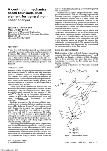
A continuum mechanicsbased four-node shellelement for general nonlinear analysisEduardo N. Dvorkin andKlaus-Jürgen BatheDepartment of MechanicalEngineering,Massachusetts Institute of Technology,Cambridge,MA 02139, USA(Received December 1983)ABSTRACTA new four-node (non-flat) general quadrilateral shellelement for geometric and material non-linear analysis ispresented. The element is formulated using threedimensional continuum mechanics theory and it is applic able to the analysis of thin and thick shells. The for mulation of the element and the solutions to various testand demonstrative example problems are presented anddiscussed.INTRODUCTIONthin and thick shells of arbitrary geometries for generalnon-linear analysis.The objective in this paper is to present a simple 4-nodegeneral shell element with the following properties: theelement is formulated using three-dimensional stress andstrain conditions without use of a shell theory; theelement is applicable to thin and thick shells and can beemployed to model arbitrary geometries; the element isapplicable to the conditions of large displacements androtations but small strains, and can be used effectively inmaterially non-linear analysis.The formulation of the element is quite simple andtransparent, and the element has good predictive capa bility without containing spurious zero energy modes.In the next section of the paper we discuss some basicconsiderations with respect to the assumptions used, andin the following section we present the element for mulation for non-linear analysis. The results obtained innumerical solutions that demonstrate the properties ofthe element are given in the final section.BASIC CONSIDERATIONSThe formulation of the 4-node shell element represents anextension of the shell element discussed previously2,3, andwe therefore use the same notation as in those references.Also, to focus attention onto some key issues of theformulation, we consider in this section only linearanalysis conditions.The geometry of the element (see Figure 1) is describedusing2:The finite element analysis of general shell structures hasbeen a very active field of research for a large number ofyears14,29. However, despite the fact that many differentshell elements have already been proposed, the search fora shell element capable of representing the general non linear behaviour of shells with arbitrary geometry andloading conditions in an effective and reliable manner isstill continuing very actively.During recent years it has become apparent that twoapproaches for the development of shell elements are veryappropriate: (1) the use of simple elements, based on thediscrete-Kirchhoff approach for the analysis of thinshells 2,5-9 ; (2) the use of degenerated isoparametricelements in which fully three-dimensional stress andstrain conditions are degenerated to shellbehaviour 2,3,5,7,17,19,24,29 .The latter approach has the advantage of being inde pendent of any particular shell theory, and this approachwas used by Bathe and Bolourchi3 to formulate a generalshell element for geometric and material non-linearanalysis. This element has been employed very success fully when used with 9 or, in particular, 16 nodes.However, the 16-node element is quite expensive, andalthough it is possible to use in some analyses only a fewelements to represent the total structure (see later exa mples) in other analyses still a fairly large number ofelements need by employed5.Considering general shell analyses, much emphasis hasbeen placed onto the development of a versatile, reliableand cost-effective 4-node shell element16'17,22,28. Suchelement would complement the above high-order 16-nodeelement and may be more effective in certain analyses. Thedifficulties in the development of such element lie in thatthe element should be applicable in a reliable manner to0264-4401/84/010077-12 2.00 1984 Pineridge Press LtdEng. C o m p u t , 1984, Vol. 1 , March77
A four-nodeshell element for non-linearanalysis: E. N. Dvorkin and K. J. Bathebeen proposed 17,22,23 but there is still much room formore effective and reliable elements for general non-linearanalysis.Considering our element formulation - because theproblem lies in the representation of the transverse shearstrains - we proceed to not evaluate these shear strainsfrom the displacements in (2), but to introduceseparate interpolations for these strain components. Sincewe consider non-flat shell elements, the separate in terpolations are performed effectively in a convectedcoordinate system†.The choice of the interpolation for the transverse shearstrain components is the key assumption in our elementformulation, because adequate coupling between theelement displacements and rotations must be introducedand the element should not exhibit any spurious zeroenergy modes. For our element we use (see Figure 2):Since the kinematic relations for the above shear strainsare not satisfied using (3), we impose them usingLagrange multipliers 2,27 to obtain,where the hk(rl,r2) are the two-dimensional interpolationfunctions corresponding to node k; the ri are the naturalcoordinates; and 1xi Cartesian coordinates of any pointin the element; Cartesian coordinates of nodal point componentsof director vector at node k (which:is not necessarily normal to the midsurface of theelement); and ak is the shell thickness at node k, measuredalong the vectorThe left superscript is zero for theinitial geometry of the element and is equal to 1 for thedeformed element geometry. Note that the thickness ofthe element varies and the element is in general non-flat.The displacements of any particle with natural coor dinates ri of the shell element in the stationary Cartesiancoordinate system are:where theare the nodal point displacements into theCartesian coordinate directions, and the ak and Bk are therotations of the director vectorabout theandaxes (see Figure 1).A basic problem inherent in the use of the aboveinterpolation of the displacements, and the derivation ofthe strain-displacement matrices therefrom, is that theelement 'locks' when it is thin. This is due to the factthat with these interpolations the transverse shear strainscannot vanish at all points in the element, when it issubjected to a constant bending moment. Hence, al though the basic continuum mechanics assumptionscontain the Kirchhoff shell assumptions, the finite elementdiscretization is not able to represent these assumptionsrendering the element not applicable to the analysis ofthin plates or shells 2,5,7 . To solve this deficiency, variousremedies based on selective and reduced integration have78Eng. Comput., 1984, Vol. 1 , Marchwhere theare the contravariant components of theCauchy stress tensor 13,15 , theare the covariant com ponents of the infinitesimal strain tensor, theare the Lagrange multipliers, theare thetransverse shear strains evaluated using the displacementinterpolations in (2), andis the potential of theexternal loads. For the Lagrange multipliers we choosethe following interpolations,where 5(.) is the Dirac-delta function. This represents aweakening of the Lagrange multiplier constraint in(4)10. Substituting from (5) into (4) and invokingthatgives the distinct constrains:Hence, the complete element stiffness matrix is calculatedusing the functional:† Note that in refs. 2 and 3, the shell element formulation is discussed inthe global stationary coordinate system, because all displacementcomponents are interpolated in the same way. To emphasize that we usehere stress and strain measures in the convected coordinate system, weplace a tilde ( ) over these quantities.
A four-nodeshell element for non-linearanalysis: E. N. Dvorkin and K. J. Bathethat the bending stress predictions are relatively littleaffected by element distortions (see examples).To employ (7), we also need to use the appropriateconstitutive relations:whereis the fourth-order contravariant constitutivetensor in the convected coordinates ri. The constitutivelaw is known in the local Cartesian system of orthonormalbase vectorsi 1,2,3, with the conditionequal tozero 2 , (see Figure 3). Denoting this constitutive tensor bythe constitutive tensor for (8) is obtained usingthe transformation:where the gi are the contravariant base vectors of theconvected coordinates ri. These vectors are calculated,using the covariant base vectors gi, where:with stress and strain components in convected coor dinates and (1) and (2) to evaluate the straincomponents(3) to evaluate the straincomponents; and (6) to express the variablesin terms of the nodal point displace ments and rotations of (2).Considering the representation that we have chosen forthe transverse shear strains, we can make the followingthree important observations:(1) The element is able to represent the six rigid bodymodes. The element contains the rigid body modesbecause zero strains are calculated in the formulationwhen the element nodal point displacements and rota tions correspond to an element rigid body displacement.This can be verified by using (1) to (6) to evaluatethe strains, but more easily we can use the fact thatthe 4-node shell element of reference 3 satisfies the rigidbody mode criterion. Hence, for a rigid body displace ment theare zero, from which it follows thatalso the shear strains in (3) are zero, and the rigid bodymode criterion is satisfied.(2) The element can approximate the Kirchhoff-Lovehypothesis ofnegligible shear deformation effects and can beused for thin shells. Various demonstrative solutions aregiven in the fourth section.(3) Based on our studies the element does not contain anyspurious zero energy modes (using a 'full' numerical in tegration). We reach this observation by studying thestrains along the element sides. If the element were tocontain a spurious zero energy mode, the strains alongevery side should vanish for a displacement pattern (to beidentified) other than the displacements corresponding toa true rigid body mode. However, such displacementpattern could not be identified.Considering the practical use of the element the in terpolation employed for the transverse shear strainsshows thatisconstant with r1 and in generaldiscontinuous at(between elements), andsimilarlyis constant with r2 and in general discon tinuous atAs a consequence, the accuracy withwhich transverse shear stresses are predicted depends to asignificant degree on the mesh used and the geometricdistortions of the elements. However, our experience iswhere Dij is the cofactor of the term gij in the matrix of themetric tensor and J is the determinant of the Jacobianmatrix at the point considered.TOTAL LAGRANGIAN FORMULATIONThe large displacement formulation of the shell element isbased on the derivation given in ref. 2 (Section 6.3.5), andthe concepts and interpolations presented in the previoussection.The geometry of the element at any time t is defined asin (1) but using the nodal point coordinates,anddirector vectorswhere we imply summation over k. The displacements,and incremental displacements, ui, of a particle of theelement at time t are hence given by:where theare the nodal point displacements at time t,the are the incremental nodal point displacements fromthe configuration at time t, and the variablesand βk are defined as in (2) but referred to the configu ration at time t.This kinematic description implies the following hy† Note that the superscript t on a variable denotes the configuration attime t in the incremental solution, and does not imply a dynamicanalysis.Eng. Comput., 1984, Vol. 1 , March79
A four-nodeshell element for non-linearanalysis: E. N. Dvorkin and K. J. Bathepotheses: the director vectors remain straight during thedeformations; the 'thickness' of the element measuredalong the director vectors remains constant during thedeformations; hence only small strain conditions areconsidered.Using the assumptions in (13) and (14) thegeometric and material non-linear response is analysedusing an incremental formulation2, in which the con figuration is sought for time (load step) 't t', when theconfiguration for time t is known. The basis of thisincremental formulation is the use of the virtual workprinciple applied to the configuration at time t t. Inessence, two approaches can be employed leading to theupdated Lagrangian and the total Lagrangian formu lations. These approaches are, from a continuum me chanics point of view, equivalent, and in the following wedevelop the governingfiniteelement relations for the totalLagrangian formulation.The principle of virtual work applied to the con figuration at time t At is:where theare the contra variant components of thesecond Piola-Kirchhoff stress tensor at timeandreferred to the configuration at time 0, and thearethe covariant components of the Green-Lagrange straintensor at timeand referred to time 0. Both sets oftensor components are measured in the convected coor dinate system/ 1,2,3. The external virtual work isgiven byand includes the work due to the appliedsurface tractions and body forces.For the incremental solution, the stresses and strainsare decomposed into the known quantities,and unknown increments,so thatIn addition, the strain increment can be written as a linearpart,and a non-linear part,henceSubstituting from (16) to (18) into (15) and usingthe linearized expressionswe obtain the linearized equation of motion:This equation is the basic equilibrium relation employedto develop the governing finite element matrices. For theactual solution of problems it is frequently important touse equilibrium iterations, but the finite element matricesand vectors used in these iterations can be derived directlyfrom the matrices obtained using (19)2. Note thatis now obtained using (9) with the condition 0, which implies the more natural conditiononly in the small strain case.80Eng. Comput., 1984, Vol. 1, MarchThe basic problem of the finite element discretizationof (19) lies in expressing the strain terms of (19) interms of the finite element interpolations. Using thedefinition of the Green-Lagrange strain components:and the relations in (13) and (14) we obtain:with the notationFurther, we obtain for the transverse shear strains,using (3) and (6):
A four-nodeshell element for non-linearanalysis: E. N. Dvorkin and K. J. BatheNote that, since we assume the thickness of the shell tobe constant, the strainthrough the element thicknessis zero.The expressions in (21) to (24) are substituted into(19) which in the standard manner yields the linearstrain incremental stiffness matrixthe non-linearstrain (or geometric) incremental stiffness matrixandthe nodal point force vectorin the finite elementincremental equilibrium relations2,The element matrices in (25) correspond to fivedegrees of freedom per node (see Figure 1) but in someapplications it is convenient to use instead ofthree rotations about the global coordinate axes (seeexamples). In this case, we simply transform the matricesof (25) in the standard manner2.NUMERICAL TESTS AND EXAMPLESOLUTIONSWe have implemented our shell element in the ADINAcomputer program and have performed various numeri cal tests to study the predictive capabilities of the element.The following solutions were all obtained using 2 x 2Gauss integration in the r3 0 surface of the element, and2 and 4 point Gauss integration in the r3 direction, forelastic and elastoplastic analyses, respectively.Some simple testsAs afirststep to test the element, the eigenvalues of thestiffness matrices of undistorted and distorted elementswere calculated. In all cases, as expected, the elementdisplayed the six rigid body modes and no spurious zeroenergy modes.Patch tests. For the patch test2,18 the mesh shown inFigure 4a was used. In the first analysis (Figure 4b) themesh was loaded with the constant moment indicated anda constant curvature (linear distribution of rotations) wasobtained for both plate thicknesses in the two platedirections. The transverse displacements predicted by themodel were, as expected, those of Kirchhoff-Love platetheory at nodes 7 and 8.In the second analysis (Figure 4c) the rotational degreesof freedom were deleted and the mesh was subjected toshear forces. As expected, for both plate thicknesses alinear distribution of transverse displacements wasobtained.In the third analysis (Figure 4d) the mesh was subjectedto an external twisting moment. In the thin plate analysis,constant curvatures were obtained in both plate direc tions and the transverse displacements agreed with theanalytical thin plate theory solution. In the thick plateanalysis, a slight non-symmetry in the displacementresponse (the third digit) was obtained due to theunsymmetric representation of the transverse shear defor mations. This non-symmetry is not observed, if the sheardeformations are suppressed (which corresponds to thinEng. Comput., 1984, Vol. 1 , March81
A four-nodeshell element for non-linearanalysis: N. Dvorkin and K. J. Batheplate theory) by choosing a large value for the shearcorrection factor k (or when using rectangular elements inthe mesh)2.Finally, it should be noted that the patch test is ofcourse passed for the three membrane stress states (Τ 1 1 ,τ22 andτT 12 constants).Cantilever linear analyses. A cantilever of unit width,thickness 0.1 and lengths lOand 100 was subjected to a tipbending moment. The structure was modelled using onesingle element and two distorted elements as shown inFigure 5. The results obtained in these analyses for thedisplacements and rotations at the cantilever tip and thestresses were those of Bernoulli beam theory.Next, the cantilever in Figure 6a was analysed for thetransverse tip load shown. Using 4 equal size elements toidealize the cantilever, again good results were obtainedwhen compared with beam theoretical results (see Figure6b and Table 1).Finally, the elements modelling the cantilever weredistorted as shown in Figure 6c for a thin and a thickcantilever. The results given in Figure 6d and Table 2 showthat the transverse displacements and normal bendingstresses are almost insensitive to the element distortions.However, the calculated transverse shear stresses (notshown in the Figure) are not accurate.Linear analyses of a simply-supported plate. A simplysupported plate was considered for a static and a fre quency analysis using a consistent mass matrix. To modelone quarter of the plate the 4 x 4 mesh of equal elements(Figure 7a) was used. Figure 7b and Tables 3 and 4 give acomparison of the numerically and analytically predictedresults. The same plate was also analysed using thedistorted element mesh also shown in Figure 7a and theresults of Figure 7b and Tables 3 and 4 were obtained.82Eng. Comput., 1984, Vol. 1, MarchTable 1 Cantilever tip transverse displacement: non-distorted me shes of N elements14Table 20.7500.984Cantilever tip transverse IpointA0.9960.995η) (u3 distorted mesh)/(u 3 non-distorted mesh)
A four-nodeshell element for non-linearanalysis: N. Dvorkin and K. J. BatheAnalysis of a rhombic cantilever. The rhombic canti lever shown in Figure 8, fixed at one side and subjected toconstant pressure was analysed using a 4 x 4 elementmesh. In Table 5, the results for the transverse displace ments at six locations are compared against the solutionsobtained using the DKT triangular element6, experimen tal measurements1 and using the 16-node isoparametricelement (with 4 x 4 x 2 Gauss integration). In all cases aone step geometric non-linear analysis with equilibriumiterations was performed. Good correspondence betweenthe experimental results and the solution obtained usingour new 4-node element is observed.Linear analysis of a cylindrical (Scordelis-Lo) shellThe shell structure shown in Figure 9a has frequentlybeen used to test the performance of shell elements 12 .Figure 9b shows the solutions obtained with our elements.In each of the solutions uniform meshes with equal sizedelements were employed over one-quarter of the shell.Solutions obtained using the 3-node DKT triangularelement25 and the 16-node isoparametric element 25 arealso shown.Linear analysis of a pinched cylinderThe pinched cylinder problem shown in Figure 10a wasalso frequently analysed to test shell elements. Figure 10band Tables 6 and 7 show the convergence behaviourobtained with our new element, when comparing the finiteelement solutions11'21. Note that using the isoparametricshell element3 also a fairly large number of degrees offreedom are required to predict the response of the cylinderaccurately.Table 3 Non-dimensional displacements at centre of simplysupported plate: distorted and non-distorted meshesModelu3FEM/u3thinnon-dist.dist.plateat centre0.9950.992Table 4 Non-dimensional frequencies f (cycles/sec) for a simplysupported plate: distorted and non-distorted meshesMode shape1-11-33-3f FEM /f thin1.021.181.17plateLarge deflection analysis of a cantileverThe cantilever shown in Figure 11a was analysed for itslarge displacement and large rotation response. This is atypical problem considered to test the geometric non linear behaviour of beam and shell elements25. Figure 11aalso shows the models used in the analysis.The first two models are single element, cubic andparabolic isoparametric degenerate shell element models.Model I predicts the response of the cantilever veryaccurately, whereas model II yields an accurate responsesolution in linear analysis but locks once the element iscurved in the non-linear response solution. This obser vation is in accordance with the results reportedelsewhere5.The same nodal point layouts were next employed formodels IN and IV using our new 4-node shell element.Figures 11b-11d give the results obtained with thesemodels. It is seen that model III yields an accurate largedisplacement response prediction, and even model IVyields quite accurate results up to about 60 degrees ofrotation. The computer time required in these analyseswere only little different using models I, III and IV.Another important result is shown in Table 8. Asreported earlier5, the cubic shell element is sensitive to'in-plane' distortions, and hence it is interesting to studythe effect of using a distorted element mesh in the analysisof the cantilever (see Figures 12a and 12b). Table 8summarizes the results obtained using the one cubicelement and three 4-node elements with a nodal layoutthat corresponds to distorting the elements. It is seen thatthe predictive capability of our new 4-node element isconsiderably less sensitive to the element distortions.Eng. Comput., 1984, Vol. 1, March 8 3
A four-nodeFigure 8shell element for non-linearanalysis: E. N. Dvorkin and K. J. BatheResponse of rhombic cantilever subjected to constant pressure. q 0.26066; 10.5x10 6 ; thickness 0.125; v 0.3Table 5Deflection at locationCPU timeCPU time of x21.00approx. 2approx. 0.0480.0560.0240.0190.0190.022Geometric non-linear response of a shallow spherical shellFigure 13a shows the spherical shell that was alsoanalysed3 with one cubic shell element, modelling onequarter of the shell. To test our new 4-node shell element,the same nodal point layout was used3, giving a meshof nine elements. Figure 13b shows the responsecalculated, including the post-buckling response (notreported in ref. 3) with the automatic load steppingalgorithm 4 . Good correspondence with the analyticalsolution of Leicester2.0 and the solution of Horrigmoe 16was obtained. The solution with the 16-node element wasalmost twice as expensive as the 4-node element solution(using in both cases the same parameters for the auto matic step-by-step solution algorithm).Linear buckling analysis and large deflection response of asimply-supported stiffened plateThe stiffened plate shown in Figure 14a was analysed forits buckling reesponse. Since we expect the buckling modeto be symmetric 26 only one-quarter of the plate ismodelled using symmetry boundary conditions. Themodel consists of nine 4-node shell elements and three 2node isoparametric beam elements. At the nodes where ashell element connects to a beam element, three rotationaldegrees of freedom aligned with the global axes areconsidered for the shell element. In order to avoid lockingof the isoparametric beam elements, one point Gaussintegration along the beam axes was used. This does notintroduce spurious zero energy modes in the modelalthough the bending stiffness of the beam isunderestimated.The linearized buckling problem was solved as de scribed in reference 4(37) and we obtained:84Eng. Comput., 1984, Vol. 1, March
A four-nodeshell element for non-linearanalysis: E. N. Dvorkin and K. J. BatheNext, an initial imperfection with the shape of the firstbuckling mode and a maximum amplitude of 1/5 of theplate thickness was introduced. Figure 14b shows the largedeflection response of this model as calculated using theautomatic load stepping scheme of reference 4 with a tightenergy convergence tolerance.Analysis of elastoplastic response of a circular plateThe thin circular plate shown in Figure 15a was analysedfor its elastoplastic response, when subjected to a con centrated load at its centre. The plate is simply-supportedwith its edges restrained from moving in its plane.In a first solution, the plate model shown in Figure 15awas used to analyse the plate assuming small displace ments (materially-non-linear-only conditions). Figure 15cshows that the theoretical collapse load is overestimated,but for the coarse mesh used, the predicted response isquite reasonable.In a second solution, large displacements and elasto plastic conditions were assumed and in this case thestiffening behaviour of the plate shown in Figure 15c waspredicted. In order to have a comparison, also the modelof five axisymmetric 8-node elements shown in Figure 15bwas solved. Figure 15c shows that both models predict inessence the same response; however, in this case relativelylittle plasticity was developed for the range of displace ments considered.CONCLUSIONSTable 6Convergence study for 4-node element: pinched cylinderMesh for1/8thof shellNumber of .830.96A new four-node non-flat general non-linear shell elementhas been presented with the following important elementproperties: (1) the element is formulated using threedimensional continuum mechanics theory; hence the useof the element is not restricted by application of a specificshell theory; (2) the element is reliable and has goodpredictive capability in the analysis of thick and thinshells; (3) the amount of computations required tocalculate the element stiffness matrix are very closelythose that are used in standard isoparametric formu lations. The computer time used could be reduced con siderably in elastic analysis by using analytical integrationthrough the element thickness.In this paper we have presented the formulation andsome applications of the element. The solution resultsobtained are most encouraging, but a formal mathemati cal convergence study of the element would be veryvaluable, and we are currently pursuing such research.Finally, it should be noted that the element presentedhere provides a very attractive basic formulation thatcould be extended to large strain analysis and analysis ofcomposite shells. Also, the concepts applied here toformulate a 4-node element could equally well be em ployed in an effective manner to formulate higher-ordershell elements.ACKNOWLEDGEMENTSTable 7Comparison between displacements for 4-node and 16node elements: pinched cylinderElementMesh for 1/8thof shellNumber 045300.960.98We are grateful for the financial support by the U.S. Armycontract no. DAAK11-82-K-0005 and the ADINA usersgroup for this work.Note added in proof — We have just learned — and regretnot to have known of it earlier — that R. H. MacNeal[J. Nucl. Eng. Design, 70, 3-12 (1982)] proposed a plateelement for linear analysis that is very close to the elementpresented above.Eng. Comput., 1984, Vol. 1 , March85
A four-nodeshell element for non-linearanalysis: E. N. Dvorkin and K. J. BatheREFERENCES341286Adini, A. Analysis of shell structures by the finite element method,PhD Dissertation, Department of Civil Engineering, University ofCalifornia, Berkeley (1961)Bathe, K. J. Finite Element Procedures in Engineering Analysis,Prentice-Hall, Englewood Cliffs, New Jersey (1982)Eng. Comput., 1984, Vol. 1, March5Bathe, K. J. and Bolourchi, S. A geometric and material nonlinearplate and shell element, J. Comput. Struct., 11, 23-48 (1979)Bathe, K. J. and Dvorkin, E. N. On the automatic solution ofnonlinear finite element equations, J. Comput. Struct. 17, (5-6),871-879 (1983)Bathe, K. J.,Dvorkin, E. N. and Ho, L. W. Our discrete-Kirchhoffand isoparametric shell elements for nonlinear analysis - anassessment, J. Comput. Struct., 16, (1-4), 89-98 (1983)
A four-nodeshell element for non-linear67891011121314151617analysis: E. N. Dvorkin and K. J. BatheBathe, K. J. and Ho, L. W. A simple and effective element foranalysis of general shell structures, J. Comput. Struct., 13,673-382 (1980)Bathe, K. J. and Ho, L. W. Some results in the analysis of thinshell structures, Nonlinear Finite Element Analysis in StructuralMechanics, (Ed. W. Wunderlich et al.). Springer-Verlag, Berlin(1981)Batoz, J. L., Bathe, K, J. and Ho, L. W. A study of three-nodetriangular plate bending elements, Int. J, Num. Meth. Eng., 15,1771-1812(1980)Batoz, J. L. and Ben Tahar, M. Evaluation of a new quadrilateralplate bending element, Int. J, Num. Meth. Eng., 18, 1655-1677(1982)Bercovier, M., Hasbgni, V., Gilon, Y, and Bathe, K, J, On a finiteelement procedure for nonlinear incompressible elasticity, Hy brid and Mixed Finite Element Methods, (Ed, S. M. Atluri et al.),John Wiley, New Yo
dimensional continuum mechanics theory and it is applic able to the analysis of thin and thick shells. The for mulation of the element and the solutions to various test and demonstrative example problems are presented and discussed. INTRODUCTION The finite element analysis of general shell structures has been a very active field of research .