Transcription
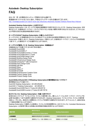
Modelling KLH structures withAUTODESK Robot Structural Analysis ProfessionalThis FAQ will help you to model your KLH structure with AUTODESK Robot Structural Analysis Professional(further referred to as “Robot Structural” within this document). It is assumed that a model has already beenbuilt and only KLH-specific information is missing.Step 1: Material DefinitionEnsure that KLH default settings are applied in the “Job Preferences” with Eurocode material set. A “CLT KLH”material (which is used independently from the panel type) can be defined as shown:Note: The material values you aplly here do not influence the results as long as the stiffness parameters are given correctly.The Specific weight will be used to calculate the self weight of the structure (in combination with the total thickness “Th”).–1/6–
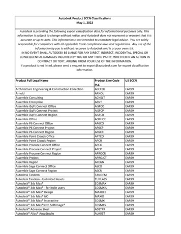
Modelling KLH structures withAUTODESK Robot Structural Analysis ProfessionalStep 2: Definition of the KLH panel type – overviewStep 2a:Name the KLH panel type by clicking on “ ” and define the panel by clicking on “Definition method”.Note: When the name and the values are entered onto a computer, they will always be available. The definition also canbe transferred between machines by copying the file.–2/6–
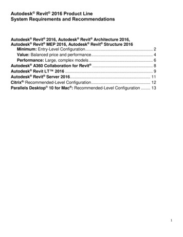
Modelling KLH structures withAUTODESK Robot Structural Analysis ProfessionalStep 2b: Panel name and thicknessSwitch to the “Orthotropy” tab: Name the “Label” with the KLH panel you want to calculate. Define the“Thicknesses” “Th”, and select the “Material” from the drop-down menu as “CLT KLH”, as shown in followingwindow and click “Define” by “Stiffness matrices (orthotropy)”.Note: The thicknesses “Th”, “Th1” and “Th2” (total and sums of in x- and y-direction) have to be added manually. Theydo not influence the results, if the correct stiffness parameters are given (see step 2d).–3/6–
Modelling KLH structures withAUTODESK Robot Structural Analysis ProfessionalDefinition of local system axes (panel directions)You can view local systems in Robot Structural by clicking the box in the bottom left corner, and change panelorientation as shown below:Note: The local x-direction of the panel is always the direction of outer layers (according to the definitions in KLHdesigner).–4/6–
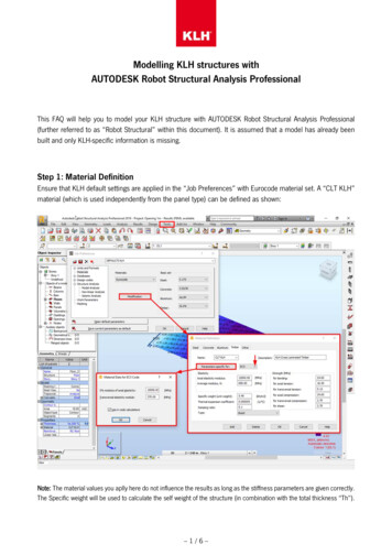
Modelling KLH structures withAUTODESK Robot Structural Analysis ProfessionalStep 2c: Stiffness propertiesOpen your browser and go to www.klhdesigner.at or open your KLHdesigner desktop application. Choose theKLH panel you want to use in Robot Structurual to obtain the associated stiffness properties.Shear stiffness matrix H (kN/m)Flexure stiffness matrix K (kN*m)Membrane stiffness matrix D (kN/m)Note: You are able to change the units by clicking on the button as shown in the graphic above.–5/6–
Modelling KLH structures withAUTODESK Robot Structural Analysis ProfessionalStep 2d: Stiffness Matrices in Robot StructuralReturn to Robot Structural and fill in the stiffness values obtained from KLHdesigner into the defined array asshown below and finally click “Add”.Membrane stiffness matrix D (kN/m)Flexure stiffness matrix K (kN*m)Shear stiffness matrix H (kN/m)Note: Once you have defined a KLH panel with this procedure, it can be used for future models on this computer.–6/6–
AUTODESK Robot Structural Analysis Professional - 1 / 6 - This FAQ will help you to model your KLH structure with AUTODESK Robot Structural Analysis Professional (further referred to as "Robot Structural" within this document). It is assumed that a model has already been built and only KLH-specific information is missing.