Transcription
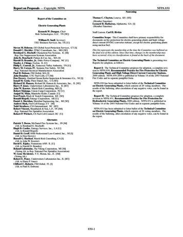
National Fire Sprinkler Association 20161TOP 10 CHANGES TO THE2016 EDITION OF NFPA 13 –WHAT’S NEW FORSPRINKLERS?Victoria B. Valentine, P.E.NFPA 13 – 2016 Edition2 First Revisions – August 2013Second Revisions – June 2014Membership Vote – June 2015Published – October 2015Public Input Due for the 2019 Edition June 2016 National Fire Sprinkler Association 2015
10. Main Drain Sizing3Main Drain Sizing4 No longer mandates a maximum size for maindrainsThis allows the main drain as a method forperforming forward flow tests for backflowpreventions devices, if desired. National Fire Sprinkler Association 2015
Main Drain Sizing5Riseri or MainiSize (inches)2013 – DrainiConnection(inches)2016 – DrainiConnection(inches)Up to 2¾ or larger¾ or larger2 ½,, 3,, 3 ½1 ¼ or largerg1 ¼ or largerg4 and larger2 only2 or larger9. Adjacent Hazards/DesignM h dMethods6
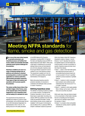
Adjacent Hazards7 11.1.2* Adjacent Hazards or Design Methods.– (1) Increase highest design area by 15 feet,feet– (2) barrier located above an aisle, horizontally a minimumof 2 ft (0.6 m) from an adjacent hazard,– (3) a change in ceiling height between adjacent hazards,which is at least 2 feet, and located above an aisle,horizontally a minimum of 2 ft (0.6m) from an adjacenthhazardd.Adjacent Hazards8Light Hazard2 ft. minimumaisle widthOrdinary Hazard2 ft. minimumaisle width
Adjacent HazardsClass IV 15 ft High Storage2 ft. mminimumaisle width2 ft. mminimumaisle width9Group A Plastic 20 ft High Storage8. Pipe Stands10
Pipe Stands11 Registered professional engineer is permitted todesign an alternativealternati eCalculations must include system details and safetyfactors incorporatedConsidered structure equivalentPipe Stands (continued)12 Must be ferrous OtherOh materialsi l proven bby firefi testingiSpaced per distances in Table 9.2.2.1
Pipe Stands (continued)13 Sizing PerPTableT bl 9.2.6.3.192631 Short pipe stand exception Maximum4 ft (base of pipe stand to centerlineof the supported pipe) 2-inch pipe stand Can Mustsupport up to 10-inch Schedule 40be axially loadedPipe Stands (continued)14SystemyPipe1½Diameter inch1 ½ inch 6.6 ftPipe Stand Diameter22½34inch inch inch inch9.9 ft2 inch 4.4 ft11.32 ½ inch8.1 ft ft3 inch5.2 ft4 inch to8 inch13.8ft18.0ft14.7ft6inch26.8fft
Pipe Stands (continued)15 Base SecuredSdbyb approvedd methodh d Minimum of four anchors attached to the floor Allowances for short pipe stands meeting the previousexceptionPipe Stands (continued)16 U-bolt or equivalent connection to system pipingMMaximumcantilever attachment off 1 ftf Bracket sized by section modulus in Table 9.2.6.5.3Thrust from system operation accounted for
Pipe Stands (continued)17 Additional Considerations ExteriorEiapplicationli i Areas subject to earthquakes7.Openings in Concealed Spaces18
Small Openings in Concealed Spaces19 8.15.1.2.1.2. Small openings with a combined totalarea of not more than 20 percent of the ceiling,ceilingconstruction feature, or plane used to determine theboundaries of the concealed space shall bepermitted where length greater than 4 ft (1.2 m)shall not have a width greater than 8 in. (200 mm). National Fire Sprinkler Association 20156. Clearance to Obstructions20
3x and 4x Spacing Rule21 When applying the rules of 8.6.5.2.1.3 (“threetimes rrule”)le”) the maximumma im m clear distance for spraysprasprinklers of 24 inches has been eliminated forobstructions in the vertical orientation such ascolumnsSimilar changes were made to the 4x rule forextended coverage sprinklers National Fire Sprinkler Association 20153x and 4x rule22 8.6.5.2.1.3* Minimum Distance from Obstructions. Unlessthe requirements of 8.6.5.2.1.48 6 5 2 1 4 through 8.6.5.2.1.98 6 5 2 1 9 aremet, sprinklers shall be positioned away fromobstructions a minimum distance of three times themaximum dimension of the obstruction (e.g., structuralmembers, pipe, columns, and fixtures) in accordancewith Figure 8.6.5.2.1.3(a) and Figure 8.6.5.2.1.3(b).(A) The maximum clear distance required shall be 24 in.(B) The maximum clear distance shall not be applied toobstructions in the vertical orientation (e.g., columns). National Fire Sprinkler Association 2015
3x and 4x rule23 National Fire Sprinkler Association 20155. Air Vents24
Air Venting25 7.1.5 Air Venting. A single air vent with a connectionconforming to 8.16.68 16 6 shall be providedpro ided on each wetpipe system utilizing metallic pipe.This section is clear that all wet pipe sprinklersystems installed in accordance with the 2016edition of NFPA 13 and using metallic pipe requirethe inclusion of an air vent.Air Venting26 7.1.5.1 Venting from multiple points on each systemshall not be required.req iredThis section clarifies that it is not required to ventfrom multiple locations in a system National Fire Sprinkler Association 2015
Air Venting27 Starting in the 2013 edition of NFPA 13, thedefinition of a systems stem was changed to clarifyclarif that asystem is the piping that includes a water supplysource, a control valve, a waterflow alarm and adrain.This means that each floor of a multi-story buildingwith a FCVA is a separate system each with an airvent. National Fire Sprinkler Association 2015Air Venting28 8.16.6* Air Venting. The vent required by 7.1.5shall be located near a high point in the ssystemstem toallow air to be removed from that portion of thesystem by one of the following methods:(1) Manual valve, minimum ½ in. size(2) Automatic air vent(3) Other approved means
4. Concrete Anchors29Concrete Anchors30 Prying Factor (3.11.9) Affactor bbasedd on fittingfi i geometry andd bracebanglelfrom vertical that results in an increase in tension loaddue to the effects of prying between the upper seismicbrace attachment fitting and the structure. Indicated with manufacturers data
Concrete Anchors (continued)31 Prequalified for seismic application with ACI 355.2,Q lifi tiQualificationsoff PPost-Installedt I t ll d MechanicalM h i lAAnchorsh iinConcrete and CommentaryUse Table 9.3.5.12.2(a) through Table 9.3.5.12.2(f)for loadsConcrete Anchors (continued)32 Allowable load can be calculated SoftwareS fpermittedi d as longlas iti accounts ffor pryingiwith concrete anchors Has to be seismically prequalified Calculated ASD values are per ACI 318 Chapter 17and consider prying effecting, brace angle, andoverstrength factor Alternative designed by professional engineer perbuilding codes
3. Commodity Classification33Classification of Commodities34 5.6.1.1.1 CommodityClassification and thecorrespondingdi protectionirequirements shall bedetermined based on themakeup of individual storageunits (i.e, unit load, palletload).5.6.1.1.1.1 The type andamount of materials used aspart of the product and itsprimary packaging as well asthe storage pallet shall beconsidered in the classificationof the commodity.
Pre-2016 Mixed Commodity35 5.6.3.3.2 - Class III Commodity ClassIII commodity shall be permitted to contain alimited amount (5 % by weight or volume or less) ofGroup A or Group B plastics. 5.6.3.4.1 – Class IV Commodity ClassIV commodity shall be defined as a product, withor without pallets, that meets one of the followingcriteria: (1)Constructed partially or totally of Group B plastics (2) Consists of free-flowing Group A plastic materials (3) Contains within itself or its packaging an appreciableamount (5 % to 15 % by weight or 5 % to 25 % by volume)of Group A plastics5.6.3.4.1 – Class IV Commodity(Graphical Representation of old text)IVIII
2016 Class III & Class IV37 Class III and Class IV can contain a limited amountof GroupGro p A plastics:plasticsCartoned – Figure 5.6.3.3(A)Exposed – Figure 5.6.3.3(B)2016 National Fire Sprinkler Association2016 Edition – Figure 5.6.3.3.3(a)38Commodities Containing a Mixture of Expandedand Unexpanded Group A Plastics – Cartoned
2016 Edition – Figure 5.6.3.3.3(b)39Commodities Containing a Mixture of Expandedand Unexpanded Group A Plastics – Exposed5.6.4.1 – Plastics Reclassified40 Added to Group A Plastics: (5)CellulosicsCll l i (cellulose( ll lacetate, cellulosell lacetatebutyrate, ethyl cellulose) (Formerly (8)Group B)Natural rubber (not expanded) (Formerly (10)Nylon (nylon 6,6 nylon 6/6) (Formerly (20)Group B)Group B)PVF (polyvinyl fluoride) (FormerlyGroup C)
2. Cloud Ceilings41Cloud Ceilings42 National Fire Sprinkler Association 2015
Cloud Ceiling43Definition (3.3.5.1). “AnyA ceiling system installed in the same plane withhorizontal openings to the structure above on allsides. This does not include sloped ceilings asdefined in 3.3.5.4.” National Fire Sprinkler Association 2015Cloud Ceiling44 Cloud Ceilings (8.15.24)N section provides guidance on when sprinklersNewmay be omitted from above a cloud ceiling.Based upon the results of a Fire Protection ResearchFoundation projectThe basic premise is that under a certain set ofcircumstances, sprinklers located below the cloudsonly will provide adequate fire protection. National Fire Sprinkler Association 2015
Cloud Ceiling45 Sprinklers shall be permitted to be omitted aboveclo d ceilings where both of the following apply:cloudappl Theopenings around the cloud and the maximumsprinkler protection area meet the requirementsof 8.15.1.2.1.2 and Table 8.15.24.1 The requirements of 8.15.24.2 are met. (Note:8.15.1.2.1.2 was intended to be 8.15.1.2.1.3) National Fire Sprinkler Association 2015Cloud Ceiling46 8.15.1.2.1.3The space above cloud ceilings meeting therequirements in 8.15.24.1 and having openings witha combined total area of not more than 20 percentof the ceiling, construction feature, or plane used todetermine the boundaries of the concealed spaceshallh ll beb permitted.itt d National Fire Sprinkler Association 2015
Cloud Ceiling47 Table 8.15.24.1 Maximum Sprinkler Protection AreaBased on Ceiling Cloud Width and Opening WidthCeiling Cloud —Minimum WidthDimension (ft)Maximum AreaMaximum AreaMaximum Area(ft2) — Opening (ft2) — Opening (ft2) — OpeningWidth 0.5 in./ ft Width 0.75 in./ ft Width 1 in./ ft ofof Ceiling Height of Ceiling Height Ceiling Height2 to 2.517570NP2.5 to 422512070 4225150150 National Fire Sprinkler Association 2015Annex to 8.15.24.1(1)48 The maximum allowed gap distance for omission ofsprinklers above cloud ceilings formula.formulaA/B XA inches of gap between clouds or between a cloud and a wallB ceiling heightX maximum inches of gapExample:pA 8 in. maximum gap dimensionB 14 ft ceiling heightX 8/14 0.57 inch of gap/ft of ceiling height
49Cloud Ceiling Installation Rules8.15.24.2 All sprinklers shall be quick response standardspra or extendedspraye tended coverageco erage pendent or uprightprightsprinklers.Where extended coverage sprinklers are used, themaximum distance between sprinklers shall notexceed 16 ftMaximum cloud ceiling height shall not exceed 20ft. National Fire Sprinkler Association 2015Cloud Ceiling Example50Cloud Array (6ft x 6ft) 14 ft elev.4-inch gap between clouds & wall
Cloud Ceiling Example51Step 1:Does Cloud Meetdefinition?YesStep 2:Is Cloud 20 ft orless?YesCloud Ceiling Example52Step 3: What isMax spacingMax.allowed?
Annex to 8.15.24.1(1)53 A/B XA inchesi h off gap betweenb tcloudsl d or betweenb ta cloudl d anddawallB ceiling heightX maximum inches of gap Example:4/14 0.30 3 inch of gap/ft of ceiling height National Fire Sprinkler Association 2015Table 8.15.24.154 Maximum Sprinkler Protection Area Based onCeiling CloudClo d Width and Opening WidthMaximum Area Maximum Area Maximum AreaCeiling Cloud — (ft2) — Opening (ft2) — Opening (ft2) — OpeningMinimum Width Width 0.5 in./ ft Width 0.75 in./ Width 1 in./ ftDimension (ft)of Ceilingft of Ceilingof CeilingHeightHeightHeight2 252– 2.517570NP2.5–422512070225150150 4 National Fire Sprinkler Association 2015
Cloud Ceiling Example55Step 3: What isMax spacingMax.allowed?225 sq. ft.Cloud Ceiling Example56QR Sprinklers spaced at 225 sq. ft.
1. Exposed Expanded Group APl iPlastic57Exposed Expanded Plastics on expanded-group-a-plastics2016 National Fire Sprinkler Association
Exposed Expanded Plastic up to 25 ft59 17.2.3.5* Protection of Exposed Expanded GroupA Plastics.PlasticsThe maximum storage height shall be 25 ft.The maximum ceiling height shall be 40 ft.Sprinklers shall be intermediate temperature–ratedESFR pendent sprinklers with a nominal K-factor ofK-25.2Exposed Expanded Plastic up to 25 ft60 12 sprinklers design areaThe minimum operating pressure shall be either 30psi or 60 psiA) 30 psi for storage heights up to 25 ft with a maximumceiling height of 30 ftB) 60 psi (4.1 bar) for storage heights up to 25 ft. (7.6 m)withith a maximumiceilingili hheighti ht off 40 ft (12.2(12 2 m).) The minimum aisle width shall be 8 ft (2.4 m).
61Vertical Barriers for ExposedExpanded PlasticsPicture courtesy of FPRF Report6217.2.3.5.8 Vertical Barriers forExposed Expanded Solid vertical face of rack to face of rack, spacedat a maximum 16.516 5 ft (5.0(5 0 m) intervalinterval.Extend a maximum of 4 in. (102 mm) above thefloor to the maximum storage height.Area of storage between vertical barriers andaisles not exceed 124 ft2 (11.52 m2)Extend across the longitudinal flue.Commodity shall be permitted to extend a nominal4 in. (102 mm) beyond the vertical barrier at theaisle.
Exposed Expanded Plastic over 25 ft63 Section 17.3.3.5Similar requirements as storage over 25 feet.fDifferences include: Maximumstorage height of 35 ft (10.6 m). Maximum ceiling height of 40 ft (12.2 m). Minimum operating pressure of 60 psi (4.1 bar). National Fire Sprinkler Association 2016THANK YOU!valentine@nfsa.org64
Adjacent Hazards 7 11.1.2* Adjacent Hazards or Design Methods. - (1) Increase highest design area by 15 feet, - (2) barrier located above an aisle, horizontally a minimum of 2 ft (0.6 m) from an adjacent hazard, - (3) a change in ceiling height between adjacent hazards, which is at least 2 feet, and located above an aisle, horizontally a minimum of 2 ft (0.6m) from an adjacent

![Public Input No. 12-NFPA 497-2014 [ Chapter 2 ]](/img/62/497-a2016-eec-aaa-fd-piresponses.jpg)