Transcription
White paper Version 01.00LTE-Advanced Pro IntroductioneMBB Technology Components in3GPP Release 13/14White paperLTE-Advanced-Pro Introduction White paper en 5215-8258-52 v0100.indd 104.05.2018 10:47:46
Table of contentsIntroduction.42LTE-Advanced Pro technology components relevant to eMBB.52.1Efficient use of unlicensed frequency d access (LAA, Release 13).92.1.2.1 Overview.92.1.2.2 Frame structure type 3.92.1.2.3 Listen before talk.112.1.2.4 Discontinuous transmission.132.1.2.5 Discovery reference signal in LAA.142.1.2.6 Radio resource management in LAA .152.1.3Enhanced LAA (eLAA, Release 14).162.1.3.1 Introduction.162.1.3.2 New uplink waveform for eLAA.172.1.3.3 LBT for eLAA.182.1.4LTE-WLAN radio level integration and inter working enhancement(LWA and enhanced LWA).182.1.4.1 LWA mobility.192.2Carrier aggregation beyond 5CC.212.2.1Physical layer impact of CA beyond 5CC.222.3Multiuser superposition transmission (MUST).242.3.1Multiuser superposition transmission schemes.262.3.2MUST signaling aspects for network and UE.302.4Dual connectivity enhancements.312LTE-Advanced-Pro Introduction White paper en 5215-8258-52 v0100.indd 204.05.2018 10:47:46
2.5Single-cell point-to-multipoint (SC-PTM).322.6Base station antenna evolution.352.6.1Radiated requirements for active antenna systems (AAS).372.6.1.1 Radiated transmitter characteristics.382.6.1.2 Radiated receiver characteristics.392.6.2Full dimension MIMO (FD-MIMO).402.6.3Enhanced full dimension MIMO (eFD-MIMO).433Conclusion.454LTE/LTE-Advanced frequency bands .465Literature.486Additional information.49When LTE was first specified as a fourth generation cellular communication technology, the main targetuse case was to provide high data rate services to mobile end users, e.g. smartphones. With the recentenhancements provided by 3GPP Release 10 through 3GPP Release 12, also known as LTE-Advanced, themobile data use case remained dominant although additional improvements such as NB-IoT and device-todevice communications indicated optimization towards new and diverse use cases. From 3GPP Release 13onwards, further improvements clearly lead towards the support of a triangle of use cases similar to thoseaddressed by 5G. In addition to efficient support of enhanced mobile broadband services, the aim is to costefficiently support massive machine type connectivity as well as low latency and reliable communicationsmotivated by vertical industries such as automotive, eHealth and robots. This white paper summarizes theLTE-Advanced Pro enhancements in 3GPP Releases 13 and 14 that address the mobile broadband use case.More detailed descriptions of the enhancements in 3GPP Releases 10, 11 and 12 are available in [1], [2] and[3].Rohde & Schwarz White paper LTE-Advanced Pro Introduction 3LTE-Advanced-Pro Introduction White paper en 5215-8258-52 v0100.indd 304.05.2018 10:47:46
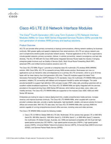
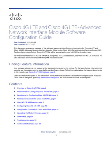
IntroductioneMBBUltra-reliable low-latency communications (URLLC) opens up an entirely new use casefamily whose aim is to support new requirements from vertical industries, e.g. autonomous driving from automotive, remote surgery from eHealth and robotics from Industry4.0. The LTE-Advanced Pro technology components provided by 3GPP Releases 13 and14 indicate a transition phase towards the coverage of this 5G use case triangle. Fig. 1.1illustrates the technology component dependency on top of LTE-Advanced as specifiedup to and including 3GPP Release 12. Section 2 of this white paper provides a detaileddescription of the eMBB technology components.URLLCmMTCConcrete and confined use cases such as mobile voice in 2G and mobile data in 4G dominated the definition of past cellular technologies. In contrast, 5G introduces a paradigmchange towards a user/application centric technology framework that aims to supportthe following triangle of important use case families. The enhanced mobile broadband(eMBB) use case represents the well-known continuation of the ever-increasing requirement to support both higher peak data rates per user and more system capacity. Massivemachine type communications (mMTC) describes a use case family that allows billionsof devices to be connected in a cost-efficient way while not overloading the cellular network. In 5G, this is sometimes also referred to as massive Internet of Things (mIoT).Fig. 1.1: LTE-Advanced Pro 3GPP Release 13/14 technology component dependencies.LTE-Advanced Pro 3GPP Release 13/14 technology component acityenh.eFD MIMOeLWIPenh. LWALAAeMTCLightconnectionLWIPDC enh.LWAAASSC-PTMFD MIMOCA enh.NB-IoTL2 latencyreductionV2XservicesfeMTCeNB-IoTURLLCMTCPHX enh.for MTCNAICSEnh.DRXMIMOeIMTADCD2DLTE Releases 8 - 12FDD / TDDeMBMSeICICCACoMPV2V basedon sidelinkSOND2D enh.Section 3 concludes this white paper. Sections 4, 5 and 6 provide additional information,including a summary of LTE frequency bands and literature references.4LTE-Advanced-Pro Introduction White paper en 5215-8258-52 v0100.indd 404.05.2018 10:47:46
2LTE-Advanced Pro technology componentsrelevant to eMBBSince it was first introduced in 2010, LTE/LTE-Advanced technology has been continuallyimproved by adding new technology components and enhancing existing ones. 3GPPhas used the UE category concept since the initial specification of the LTE technology.For LTE specified in Release 8 to Release 11, a single UE category describes an overallcapability. The UE also indicates support for individual capabilities via dedicated signalingas listed in [11]. This includes physical layer and RF parameters (e.g. supported frequencybands), inter-RAT parameters (e.g. FDD or TDD) and many more. Table 2.1 summarizesthe UE capabilities in the DL and UL described by the UE category.Table 2.1: UE capabilities based on UE category up to 3GPP Release 11.UE categoryMax. datarate in MbpsCCDLULDL1 10 512 50 25 503 1004 1505 300 756 300 50MIMOModulationULDLULDLUL11164QAM16QAM241127 300 10014141 3000 150055849 450 50212/41 450 1002 600 50211 100216QAM2/424/412/2/44 60064QAM2/2/231264QAMIncluding enhanced MIMOschemes(DL/UL) andDL carrier aggregation as of3GPP Release112/2/231116QAM281064QAM2/23Initial specification asof 3GPP Release 864QAM2/22Comment2/2/2/214/432/2/442/2/2/22The base station needs to respect the signaled UE radio access capability parameterswhen configuring and scheduling the UE.3GPP Release 12 introduced new separate categories in the downlink and uplinkdirection, i.e. instead of a single UE category, UE DL category and UE UL category fieldsare defined. This separation is maintained in subsequent 3GPP Releases. Table 2.2 provides an overview of DL capabilities related to the DL category field. Note that the number of component carriers (CC), the number of spatial layers (MIMO) and the modulationsin Table 2.2 and Table 2.3 are examples, i.e. additional combinations are possible.Rohde & Schwarz White paper LTE-Advanced Pro Introduction 5LTE-Advanced-Pro Introduction White paper en 5215-8258-52 v0100.indd 504.05.2018 10:47:46
Table 2.2: UE DL capabilities based on UE DL category field up to 3GPP Release 14.UE DLMax. datacategory rate AM256QAM added in 3GPPRelease 122/2/464QAM2/2/2256QAM 600342/2/2/264QAM4256QAM13 40012214 400058256QAM15 750 - 2/2256QAM16 100017 25000328256QAM18 /4256QAM44/4/4/8256QAM34/8/8256QAM1920 1600 2000Carrier aggregation beyond 5CC added in 3GPPRelease 13Table 2.3 provides an overview of UL capabilities related to the UL category field.Table 2.3: UE UL capabilities based on the UE UL category field up to 3GPP Release 14.UE ULcategoryMax. datarate inMbpsCCMIMOModulationComment13 1502164QAM256QAM added in3GPP Release 1414 960032264QAM15 2253164QAM16 10511256QAM17 210054256QAM18 21021256QAM19 13500164256QAM20 31531256QAM21 3004164QAM6LTE-Advanced-Pro Introduction White paper en 5215-8258-52 v0100.indd 604.05.2018 10:47:46
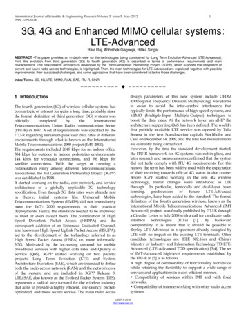
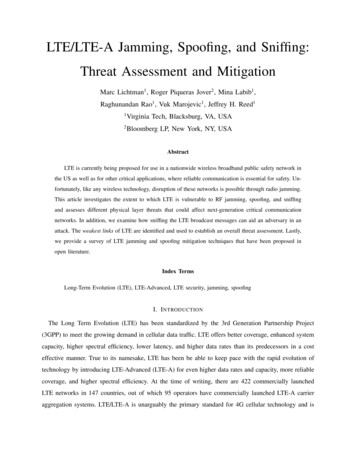
2.1Efficient use of unlicensed frequency spectrum2.1.1IntroductionSpectrum is not an infinite resource, and spectrum assets used by already deployed wireless systems – both commercial and non-commercial – cannot easily be revoked. Regulators worldwide have therefore started looking into alternatives to use the available spectrum more efficiently while exploring the concept of shared spectrum. In the meantime,the cellular industry, led by several network operators, infrastructure vendors and chipsetmanufacturers, has eyed unlicensed spectrum, particularly the 5 GHz industrial, scientificand medical (ISM) band, to serve the immediate need for additional spectrum for mobilebroadband applications due to the ever increasing mobile data traffic.The ISM bands are generally defined by the ITU Radio Regulations (Article 5) [21], but areregulated differently by each region (e.g. ETSI in Europe or FCC in USA). The exact frequency allocation and detailed regulation depends on the country (e.g. South Korea vs.Japan). Fig. 2.1 shows as an example of the IEEE channel assignments for the 5 GHz ISMband in the United States.Fig. 2.1: 5 GHz IEEE channel assignment in the United States.5 GHz IEEE channel assignment in the United StatesUsed for LTE-U in the USA, Korea, India and LAA globally5170MHzIEEE channel #UNII-15250MHzUNII-25330MHz36 40 44 48 52 56 60 645835MHzWeatherradar5490MHz5710MHzUNII-2e100 104 108 112 116 120 124 128 132 136 140 1445735MHzUNII-35815MHz149 153 157 161 16520 MHz40 MHz80 MHz160 MHz38465442625850Channels 116 and 132 may be used in some c frequency selection (DFS) required3GPP has defined multiple ways to access the 5 GHz band. Which of these methods isused depends on the network operators’ overall strategy and their existing network deployments. Fig. 2.2 shows these different methods from a high-level perspective.Rohde & Schwarz White paper LTE-Advanced Pro Introduction 7LTE-Advanced-Pro Introduction White paper en 5215-8258-52 v0100.indd 704.05.2018 10:47:47
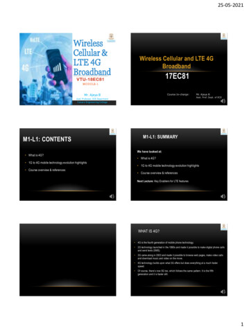
Fig. 2.2: Multiple methods defined in 3GPP to access unlicensed spectrum.Multiple methods defined in 3GPP to access unlicensed spectrumeNB(licensedfrequency band)Link aggregationLWA, LWIPeNB(unlicensedfrequency band)Carrier aggregationLAA, eLAAWLAN offloadingWi-FiWi-Fi access point2.4 GHz or 5 GHzISM bandIn the following two sections, we discuss licensed assisted access (LAA, Release 13, section 2.1.2) and enhanced licensed assisted access (eLAA, Release 14, section 2.1.3). LAA/eLAA is the dominant method for accessing the unlicensed 5 GHz ISM band. It is favoredby the majority of network operators worldwide and is therefore the focus of this section.For operators with existing WLAN deployments, two additional methods exist to combine both access technologies. These two methods are LTE-WLAN aggregation (LWA)and LTE-WLAN radio level integration with IPsec tunnel (LWIP). A high-level description is provided in section 2.1.4. For an introduction to WLAN offloading, please see theRohde & Schwarz white paper [4].To provide a complete picture, there are other non-standard-based industry alternatives,such as LTE in unlicensed spectrum (LTE-U) 1) and MuLTEFire 2), used to gain access to unlicensed spectrum. These two additional methods are not discussed in this white paper.1)2)See http://www.lteuforum.org/ for more details.MuLTEFire is a trademark of Qualcomm Incorporated; see https://www.multefire.org/ for further details.8LTE-Advanced-Pro Introduction White paper en 5215-8258-52 v0100.indd 804.05.2018 10:47:47
2.1.2Licensed-assisted access (LAA, Release 13)2.1.2.1OverviewLicensed-assisted access (LAA) is a 3GPP Release 13 feature that takes advantage of carrier aggregation. In LAA, the primary cell (PCell) is deployed in any licensed 3GPP bandacting as an anchor carrier. Secondary cells (SCell) are used in Release 13 for downlinkonly operation and are deployed in the 5 GHz ISM band (3GPP frequency band 46) toboost data rates. The regulatory requirements to access this frequency band have beencaptured in section 4 of [18]. Release 13 foresees deploying up to four LAA SCells in thisfrequency band. To enable this new functionality, additional features were introduced inRelease 13 that can be summarized as follows: Frame structure type 3 and discontinuous transmission (partial subframe) Listen before talk Additional UE signal quality measurements for carrier selectionThese features are analyzed in more detail in the following sections. The requirements forthis feature set are based on the deployment scenarios and design targets listed in [18].2.1.2.2Frame structure type 3The need to ensure fair sharing and coexistence with other technologies made it necessary to introduce frame structure type 3, which is defined in [7]. It is applicable to LAAsecondary cell operation with normal cyclic prefix only. The radio frame duration for framestructure type 3 is still 10 ms. All 10 subframes [1 ms each] are available for downlinktransmission, where a transmission can occupy one or more consecutive subframes,starting within a subframe at the first or second slot boundaries.Limiting the flexibility to start a transmission only to slot boundaries simplifies implementation at the eNB end. The transmission also does not need to end with the subframe.Instead, the downlink pilot time slot (DwPTS) architecture from frame structure type 2(TDD) is reused. That means the last subframe of the “LAA radio frame” can either befully occupied or follow one of the DwPTS durations listed in Table 2.4.Table 2.4: Configuration of special subframe 3).Configuration of special subframe (lengths of DwPTS, GP, UpPTS)Special subframe configuration0123456789103)Normal cyclic prefix in downlinkDwPTS6952 TS19760 TS21952 TS24144 TS26336 TS6952 TS19760 TS21952 TS24144 TS13168 TS13168 TSSubset of Table 4.2-1 in [7].Rohde & Schwarz White paper LTE-Advanced Pro Introduction 9LTE-Advanced-Pro Introduction White paper en 5215-8258-52 v0100.indd 904.05.2018 10:47:47
To simplify implementation on the user equipment (UE) end, the start position and thenumber of OFDM symbols of the current and next downlink subframe in that LAA SCell issignaled to the device [see Fig. 2.3].Fig. 2.3: Subframe transmitting start position via RRC signaling [14].The number of occupied OFDM symbols in the last subframe of the transmission is signaled via downlink control information (DCI) format 1C scrambled with the cell controllingradio network temporary identifier (CC-RNTI).Table 2.5: Subframe configuration for LAA in current and next subframe.Value of ‘Subframe configuration forLAA’ field in current subframeConfiguration of occupied OFDM symbols (current subframe, next subframe)0000(–, 14)0001(–, 12)0010(–, 11)0011(–, 10)0100(–, 9)0101(–, 6)0110(–, 3)0111(14, *)1000(12, –)1001(11, –)1010(10, –)1011(9, –)1100(6, –)1101(3, –)1110reserved1111reservedNote:(–, Y) means the UE may assume the first Y symbols in the next subframe are occupied and other symbols inthe next subframe are not occupied.(X, –) means the UE may assume the first X symbols in the current subframe are occupied and other symbols inthe current subframe are not occupied.(X, *) means the UE may assume the first X symbols in the current subframe are occupied and at least the firstOFDM symbol of the next subframe is not occupied.No PBCH is transmitted within frame structure type 3.10LTE-Advanced-Pro Introduction White paper en 5215-8258-52 v0100.indd 1004.05.2018 10:47:47
2.1.2.3Listen before talkLAA ensures fair sharing and coexistence with other technologies using the 5 GHz ISMband by applying the listen before talk (LBT) principle to ensure minimum channel occupancy time. A category 4 LBT mechanism based on clear channel assessment (CCA) wasadopted in LAA. Category 4 describes LBT mechanisms that use random backoff with avariable-sized contention window. The following flow chart describes the LBT procedurefor LAA in the downlink direction.Fig. 2.4: LAA Downlink LBT procedure in line with [18].LAA Downlink LBT procedure in line with (18)Idle stateNoNoYesNeed to transmit?Another TXOPneeded?YesYesChannel idle forinitial CCA period?Transmit(TXOP)NoGenerate random counternumber N out of [0, CWS]NoUpdate CWS basedon HARQ-ACKHas channelbeen idle for enhanced CAAdefer period?YesYesN 0?NoN N–1NoSense medium for oneeCCA slot durationIs channelbusy?YesLAA applies CCA in two steps: an initial CCA and an enhanced CCA. In LAA, CCA isbased on energy detection (ED) over a defined time duration that does not exceed a certain threshold value (ED threshold). In the presence of other technologies, such as Wi-Fi,the ED threshold is defined as shown in Equation 2 1. In general, the threshold is scenarioand deployment dependent since Tmax(dBm) –75 dBm/MHz 10 log10 BW, PH is definedwith 23 dBm and TA is an adjustable parameter that depends on the type of transmission. For data transmission TA 10 dB; for transmission of the discovery signal (see section2.1.2.5), TA 5 dB.Rohde & Schwarz White paper LTE-Advanced Pro Introduction 11LTE-Advanced-Pro Introduction White paper en 5215-8258-52 v0100.indd 1104.05.2018 10:47:47
Equation 2.1: Definition of energy detection (ED) threshold in LAA [9].X Thres max 72 10 log10( BWMHz / 20 MHz ) dBm, max Tmax , min T T (P 10 log10( BWMHz / 20 MHz ) P ) AHTX max With a channel bandwidth (BW) of 20 MHz for LAA SCells and a maximum base stationoutput power of 24 dBm that corresponds to a typical small cell ( local area base station, see [6]), the detection threshold ED can vary between –72 dBm/20 MHz (for data)and –68 dBm/20 MHz (for the discovery signal). The detected energy level needs to bebelow this threshold for a certain amount of time with a slot duration Tsl and defer timeTd. Tsl is 9 µs, where Td Tf mp with Tf 16 μs. mp is based on the channel access priorityclass and is therefore traffic type dependent and has a duration of at least one slot. Thedefer time is required to specifically protect Wi-Fi ACK/NACK transmission between access points and clients. As a result, the channel needs to be idle for an initial CCA periodof 34 μs and a maximum wait time of 88 µs before an LAA-capable eNB can start itstransmission.Fig. 2.5: LAA LBT procedure for downlink.LAA LBT procedure for downlinkIs channel idleduring this period?(below threshold?)Tm cot,peNB needsto transmitTXLAA SCellTslTfTimemp,minmp,maxTsl Slot durationTd Defer timemp Number of consecutive slotsTm cot,p Maximum channel occupancy timeTd,minTd,maxIf the channel is sensed to be clear, the transmitter can only transmit for a limited amountof time defined as the maximum channel occupancy time (Tm cot,p). If the channel is sensedto be occupied during that time or after a successful transmission, the “enhanced CCA”period is started by generating a random number that is within the contention window(CW). Since there are different traffic types (VoIP, video, background traffic, etc.), differentchannel priority access classes have been defined with different CW sizes and Tm cot,p[Table 2.6].Table 2.6: Channel access priority class for LAA downlink.4)Channel accesspriority class (p)4)mpCWmin,pCWmax,pTmcot,pallowed CWp sizes11372 ms{3,7}217153 ms{7,15}3315638 or 10 ms{15,31,63}471510238 or 10 ms{15,31,63,127,255,511,1023}For access classes 3 and 4, T(m cot,p) is 8 ms in the presence of other technologies such as Wi-Fi, otherwise it is 10 ms.12LTE-Advanced-Pro Introduction White paper en 5215-8258-52 v0100.indd 1204.05.2018 10:47:47
CWp ( CW size) is selected before every transmission and set to be CWmin,p based onthe channel access priority class. The random backoff counter N is now chosen from thatrange, e.g. channel priority class 3 (best effort traffic) takes a value between 0 and 15.The eNB now senses the channel for one slot duration [9 μs] and if the channel is idle, itdecrements the counter by 1. Assuming the channel stays idle, the base station continues with this procedure until N 0. If the channel is not idle after one slot duration, theeNB has to sense the channel for an additional period – the defer time Td. If the channel isdetected to be idle during Td, the eNB decrements the counter N by 1 and continues withthe procedure until N 0.The counter N is impacted by the HARQ process. If more than 80% of all transmissions inreference subframe k are NACK/DTX, CWp is incremented to the next possible value. Forpriority class 3, that would be 31.2.1.2.4Discontinuous transmissionFor LAA operation in some geographical regions (e.g. Japan), discontinuous transmissionis part of the specification. An eNB can transmit again on the LAA SCell for a maximumduration of 4 ms (Tj) immediately after sensing the channel to be idle for a sensing intervalof 34 µs (Tjs).Fig. 2.6: Discontinuous transmission for LAA, e.g. Japan.Discontinuous transmission for LAA, e.g. JapanTTotal 1000 * Tm cot,p [ Tm cot,p / Tj –1 ] * Tjs μsIs channel idleduring this period?(below threshold?)Tjs 34 μsTXTj 4 msTXLAA SCellTimeThe total transmission time needs to be less than the equation shown in Fig. 2.6. Thetransmission time Tj can therefore only become maximum if the maximum channel occupancy time (T(m cot,p)) is 2 or 3 ms, i.e. if the channel access priority class is either 1 or 2.Rohde & Schwarz White paper LTE-Advanced Pro Introduction 13LTE-Advanced-Pro Introduction White paper en 5215-8258-52 v0100.indd 1304.05.2018 10:47:47
2.1.2.5Discovery reference signal in LAAThe discovery reference signal (DRS) was introduced in 3GPP Release 12 as part of a feature set for enhancement towards small cell operation. A small cell (typically deployed asa secondary cell (SCell)) does not need to be ‘on’ all the time. However in this case, a UEcannot make quality measurements on that SCell and thus the network cannot efficientlydecide when to turn the cell back on. DRS was therefore introduced to allow a small cellto quickly transition from the off state to the on state and transmit a low duty cycle signalfor radio resource management (RRM) purposes. In Release 12, DRS consists of the first5 subframes of a radio frame to include PSS/SSS, PBCH and reference signals 5) that aretransmitted with a periodicity of 40, 80 or 160 ms.This concept has been adopted for LAA. DRS can be transmitted in any subframe withinthe discovery measurement timing configuration (DMTC) occasion that is 6 ms long. Onlyone subframe and only the first 12 OFDM symbols of this subframe are used for transmission. No PBCH is transmitted. PDSCH is only transmitted if it is scheduled in that particular subframe, in which case DRS is embedded with the data. Generally speaking, DRStransmission can be seen as a transmission on an unloaded carrier.The radio frame and subframe in which DRS can be transmitted depends on the RRC parameters (dmtcOffset, dmtcPeriodicity) that are signaled to the device.Fig. 2.7: Transmission of discovery reference signal (DRS) for LAA.Transmission of discovery reference signal (DRS) for LAADMTC periodicity (40, 80 or 160 ms)DMTC occasion (6 ms)LAA SCell #1SFN mod T [ dmtcOffset10]with T dmtcPeriodicity/10subframe dmtcOffset mod 10DMTCoffsetLAA SCell #2Primary synchronization signal (PSS)Cell-specificreferencesignalLAA DRS occupies first 12 OFDMsymbols within a subframe [1 ms]Secondary synchronization signal (SSS)DRS is subject to the LBT principle and is therefore not necessarily transmitted as periodically as indicated in Fig. 2.7.5)Cell-specific reference signals and channel state information reference signals (CSI-RS; if configured).14LTE-Advanced-Pro Introduction White paper en 5215-8258-52 v0100.indd 1404.05.2018 10:47:47
2.1.2.6Radio resource management in LAACoexistence with other technologies is very important for LAA and therefore accessingand using already congested frequencies/channels that are used by Wi-Fi access pointsand clients should be avoided. Since radio resource management (RRM) is critical for thistask, LTE defines signal quality measurements such as reference signal received power(RSRP [dBm]) and reference signal received quality (RSRQ [dB]). RSRQ is derived fromRSRP over RSSI [10], where RSSI can serve as the key performance indicator for interference on a given carrier. To measure RSSI, DRS needs to be present. But since DRSis subject to LBT, any RSSI measurement report of an LAA-capable UE needs to includetime information on when the measurements were taken. Therefore higher layers configure an RSSI measurement time configuration (RMTC) with a measurement period [40, 80,160, 320 or 640 ms], a subframe offset [0 639] and a measurement duration [1, 14, 28,42 or 70 OFDM symbols]. The device averages the RSSIs over the measurement durationand takes measurements according to the signaled periodicity [see Fig. 2.8].Fig. 2.8: Example of RMTC configuration for channel occupancy measurements based on RSSI.Example of RMTC configuration for channel occupancy measurements based on RSSIAverage over e.g. 28 RSSImeasurement samplesAverage over e.g. 28 RSSImeasurement samples0 1 2 27measDuration-r13e.g. 28 OFDM symbols 0 1 2 271 subframe [1 ms] rmtc-SubframeOffset-r13 rmtc-Period-r13. e.g. 40rmtc-Period-r13e.g. 80 ms [ 80 subframes]measDuration-r13e.g. 28 OFDM symbols rmtc-SubframeOffset-r13 rmtc-Period-r13. e.g. 40rmtc-Period-r13e.g. 80 ms [ 80 subframes]The device reports the average RSSI as well as the channel occupancy (CO), which is defined as the percentage of measured RSSI samples above a predefined (RSSI) thresholdthat is also signaled by higher layers. Both measures provide an indication of the load andinterference situation on the given LAA SCell.Rohde & Schwarz White paper LTE-Advanced Pro Introduction 15LTE-Advanced-Pro Introduction White paper en 5215-8258-52 v0100.indd 1504.05.2018 10:47:47
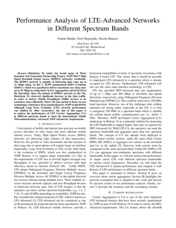
2.1.3Enhanced LAA (eLAA, Release 14)2.1.3.1IntroductionEnhanced licensed assisted access (eLAA) is part of 3GPP Release 14. It defines how userequipment can access the 5 GHz ISM band to transmit data in the uplink direction. Thefirst major difference to LAA is that generally all uplink transmissions in LTE are scheduledand therefore under the control of the serving LTE base station (eNB). Since this affectsthe channel contention between devices, the required LBT scheme that was defined inLAA for downlink operation needs to be adapted to work in the uplink direction.The second major difference is the regulatory requirements that have to be fulfilled whileusing the 5 GHz ISM band in certain regions. For example, the European Telecommunication Standardization Institute (ETSI) mandates that the occupied channel bandwidth,defined by 3GPP to be the bandwidth containing 99% of the power of the signal, shallbe between 80% and 100% of the declared nominal channel bandwidth. As an initial approach, multi-cluster PUSCH operation, standardized in 3GPP Release 10, was considered to fulfill this ETSI requirement. Multi-cluster PUSCH allows two clusters of resourceblocks to be scheduled far enough from each other to fulfill e.g. the 80% bandwidth requirement. The upper portion of Fig. 2.9 illustrates this requirement.Fig. 2.9: Regulatory requirements mandated by ETSI to transmit on 5 GHz ISM band.Regulatory requirements mandated by ETSI to transmit on 5 GHz ISM bandOccupied bandwid
LTE-Advanced Pro Introduction eMBB Technology Components in . LTE-Advanced Pro enhancements in 3GPP Releases 13 and 14 that address the mobile broadband use case. . Concrete and confined use cases such as mobile voice in 2G and mobile data in 4G domi-nated the definition of past cellular technologies. In contrast, 5G introduces a paradigm