Transcription
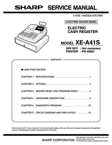
SERVICE MANUALCODE : 00ZXEA41SUSMELEAD-FREE SOLDER MODELELECTRICCASH REGISTERMODELXE-A41SSRV KEY : Not necessaryPRINTER : PR-45MIICONTENTS LEAD-FREE SOLDERCHAPTER 1. SPECIFICATIONS . . . . . . . . . . . . . . . . . . . . . . . . . . . . 1CHAPTER 2. OPTIONS . . . . . . . . . . . . . . . . . . . . . . . . . . . . . . . . . . . 4CHAPTER 3. MASTER RESET AND PROGRAM RESET. . . . . . . . . 4CHAPTER 4. HARDWARE DESCRIPTION . . . . . . . . . . . . . . . . . . . . 5CHAPTER 5. DIAGNOSTIC PROGRAM . . . . . . . . . . . . . . . . . . . . . 10CHAPTER 6. CIRCUIT DIAGRAM AND PWB LAYOUT . . . . . . . . . 15Parts marked with "!" are important for maintaining the safety of the set. Be sure to replace these parts with specifiedones for maintaining the safety and performance of the set.This document has been published to be usedfor after sales service only.The contents are subject to change without notice.
CAUTIONRISK OF EXPLOSION IF BATTERY IS REPLACEDBY AN INCORRECT TYPE.DISPOSE OF USED BATTERIES ACCORDINGTO THE INSTRUCTIONS.AVOID: SHORT-CIRCUITING THE BATTERY TERMINALS.KEEP THE BATTERY AWAY FROM FIRE.* WHEN DISPOSING THE BATTERY, FOLLOW THE LOCALRULES AND REGULATIONS.“BATTERY DISPOSAL”THIS PRODUCT CONTAINS NICKEL-METAL HYDRIDE BATTERY.THIS BATTERY MUST BE DISPOSED OF PROPERLY.REMOVE THE BATTERY FROM THE PRODUCT AND CONTACT FEDERAL ORSTATE ENVIRONMENTAL AGENCIES FOR INFORMATION ON RECYCLING ANDDISPOSAL OPTIONS.XE-A41S
LEAD-FREE SOLDERThe PWB’ s of this model employs lead-free solder. The “LF” marks indicated on the PWB’s and the Service Manual mean “Lead-Free” solder. Thealphabet following the LF mark shows the kind of lead-free solder.Example: Solder composition code of lead-free solder Lead-Free5mmSolder compositioncode (Refer to thetable at the right.)aSolder compositionSolder composition -BiiSn-Cu-NinSn-Ag-SbsBi-Sn-Ag-PBi-Sn-Agp(1) NOTE FOR THE USE OF LEAD-FREE SOLDER THREADWhen repairing a lead-free solder PWB, use lead-free solder thread. Never use conventional lead solder thread, which may cause a breakdown or an accident.Since the melting point of lead-free solder thread is about 40 C higher than that of conventional lead solder thread, the use of the exclusive-use soldering iron isrecommendable.(2) NOTE FOR SOLDERING WORKSince the melting point of lead-free solder is about 220 C, which is about 40 C higher than that of conventional lead solder, and its soldering capacity is inferior toconventional one, it is apt to keep the soldering iron in contact with the PWB for longer time. This may cause land separation or may exceed the heat-resistive temperature of components. Use enough care to separate the soldering iron from the PWB when completion of soldering is confirmed.Since lead-free solder includes a greater quantity of tin, the iron tip may corrode easily. Turn ON/OFF the soldering iron power frequently.If different-kind solder remains on the soldering iron tip, it is melted together with lead-free solder. To avoid this, clean the soldering iron tip after completion of soldering work.If the soldering iron tip is discolored black during soldering work, cleanand file the tip with steel wool or a fine filer.XE-A41SLEAD-FREE SOLDER
PC-UM10MCHAPTER 1. SPECIFICATIONS Key names1. APPEARANCERegister front viewKEY TOPRegister rear viewCustomer display(Pop-up type)Operator displayPrinter coverReceipt paperJournal windowACpower cordMode switchKeyboardDrawer lockSD memorycard slotDrawerUSB portDESCRIPTION2 (RECEIPT)Receipt paper feed key2 (JOURNAL)Journal paper feed keyRA/AMTRCPT/POReceived-on account/Amount keyReceipt print/Paid-out keyVOIDVoid keyESC/HELPEscape/Help key%1, %2Percent 1and 2 keyRFNDRefund key-Discount key@/FORMultiplication keynDecimal point keyCLClear key00, 0-9Numeric KeysPLU/SUBPLU/Sub-department keyDEPT#Department code entry keyDEPT SHIFTDepartment shift keyCLK# CONVClerk code entry/Conversion keyDept1-40Department keysINQInquiry keyTax 1 SHIFT, Tax 2 SHIFTTax 1 and 2 shift keyAUTOAutomatic sequence keyTAXTax keyCHKCheck keyCH1, CH2Charge 1 and 2 keysMDSE SBTLMerchandise subtotal key#/TM SBTLNon-add code/Time display/Subtotal keyCA/AT/NSTotal/Amount tender/Non Sale keyPrinterTake-up spoolPaper roll cradlePaper chutePrint headrelease lever2. RATINGModelWeightDimensionsPower sourcePower consumptionWorking temperatureXE-A41S12.5 kg420 (W) x 430 (D) x 302 (H) mmAC 120V, 60HzStand-by 10.0W, Operating 44.0W (max.)32 F to 104 F (0 C to 40 C)4. MODE SWITCH4-1. LAYOUT3. KEYBOARD Rotary type3-1. KEYBOARD LAYOUTManager key (MA)MAOPNormal keyboardSTD/MAX 5919 (W) x 19 (H) mmFixed typeMATypeKey positionKey pitchKey layoutREGOPX/ZOFFVOID3-2. KEY LISTX2/Z2Operator key (OP)OPPGMMGRX1/Z1 Keyboard layout[XE-A41S]RECEIPT %24561232001-NUMBERVOID 9233FDEPT CLK#SHIFT /CONVS3616TINQ AUTOUXTAX1SHIFTTAX2SHIFTVYThe mode switch can be operated by inserting one of the two suppliedmode keys - manager (MA) and operator (OP) keys. These keys can beinserted or removed only in the “REG” or “OFF” position.TAX CH1WZCHK CH2MDSE #/TMSBTL SBTLCA/AT/NSNote: The small characters on the bottom or lower right in each keyindicates functions or characters which can be used for characterentries for text programming.XE-A41S SPECIFICATIONS–1–
PC-UM10M Operator displayThe mode switch has these settings:OFF:This mode locks all register operations. (AC power turns off.)No change occurs to register data.Function message display areaClerk code or mode nameOP X/Z: To take individual clerk X or Z reports, and to take flashreports.It can be used to toggle receipt state “ON” and “OFF” by pressing he [RCP/PO] key.REG:For entering sales.PGM:To program various items.VOID:Enters into the void mode. This mode allows correction afterfinalizing a transaction.MGR:For manager’s entries. The manager can use this mode for anoverride entry.Receipt OFF indicatorNumeric entry display areaRepeat / Sentinel mark / Power save mark Clerk code or Mode nameThe mode you are in is displayed. When a clerk is assigned, theclerk code is displayed in the REG or OP X/Z mode. For example,“*01*” is displayed when clerk 01 is assigned.X1/Z1: To take the X/Z report for various daily totals.X2/Z2: To take the X/Z report for periodic (weekly or monthly) consolidation. RepeatThe number of repeats is displayed, starting at “2” and incrementalwith each repeat. When you have registered ten times, the displaywill show “0” (2 3 3.9 3 0 3 1 3 2.)5. DISPLAY Sentinel mark5-1. OPERATOR DISPLAYDisplay device: STN LCD moduleNumber of line: 2 lineNumber of digits: 16 positionsColor of display: Yellow Green / OrangeCharacter form: 5 x 7 dotsCharacter size: 8.0 (H) x 4.8 (W) mmWhen amount in the drawer reaches the amount you preprogrammed, the sentinel mark “X” is displayed to advise you to removethe money to a safe place. Power save markWhen the cash register goes into the power save mode, the powersave mark (decimal point) lights up. Function message display areaLayout:Item labels of departments and PLU/UPCs and function texts youuse, such as %1, (-) and CASH are displayed.When an amount is to be entered, ------ is displayed at the numericentry area with a guidance message “ENTER PRICE”. Numeric entry display area5-2. CUSTOMER DISPLAYDisplay device: LEDNumber of line: 1 lineNumber of digits: 7 digitsColor of display: Yellow GreenStyle: Pop up typeCharacter form: 7 segment DpCharacter size: 14.0mm (H) x 8.0mm (W)Numbers entered using numeric keys are displayed here.Date and time displayDate and time appear on the display in the OP X/Z, REG, or MGRmode. In the REG or MGR mode, press the [#/TM/SBTL] key to display the date and time.Backlight of the LCD displayWhen an error occurs or the [RFND] or [VOID] key is pressed or enterthe void mode, the green backlight will turn red.Error messageLayout:When an error occurs, the corresponding error message is displayedin the function message display area. Customer display (Pop-up type)XE-A41S SPECIFICATIONS–2–
PC-UM10M6. USB port7-3. LOGO STAMP[DEVICE] NoUSB B Type7-4. CUTTER[OUTLINE] Method : ManualThis ECR has 1 port.This is used in order to connect with a personal computer.7-5. PRINTING AREAReceipt & Journal134Number of themal head heater elements 864 )2.512.040.1254.54[SPECIFICATIONS]44.51) Transmission rate : USB 2.0 Full Speed Max 12Mbps2) Connector: USB B type3) Pin assign: 1Pin 5V: 2Pin -D: 3Pin D: 4Pin GNDReceiptJournal (units;mm)[DEVICE]SD Card (Version. 1.01)7-1. PRINTER[OUTLINE] Part number: PR-45M II NO. of station: 2 (Receipt and journal) Validation: NoXE-A41S has a SD Memory Card Slot.[SPECIFICATIONS] Printing system: Line thermal No. of dot: Receipt 288 dotsJournal 288 dots Dot pitch: Horizontal 0.125mmVertical0.125mm Font: 10 dots (W) u 24 dots (H)Variable clock rateOther commands and memory accessBus ProtocolCorrespondence capacityRecommended manufacturer: 0-25MHz: 2.7-3.6V: SPI Bus: 256MB-512MB: SanDisk9. DRAWER Printing capacity : Receipt max. 24 charactersJournal max. 24 characters Character size: 1.25mm (W) u 3.0mm (H) at 10 u 24 dots[OUTLINE] Print pitch: Column distanceRow distance Standard equipment: Yes Print speed: Approximate 50mm/s (13.3 lines/sec)1.5mm3.75mm Max. number of additional drawers: 1 The drawer consists of: Paper feed speed : Approximate 40mm/s(Manual feed)1)2)3)4): Mechanism MCBF 5 million linesHead life 12.5 million characters(at 4 dots/1 character/1 element) Paper end sensor : Set up (Receipt and journal) Cutter0.58. SD MEMORY CARD SLOT7. PRINTER Reliability44.50.5Drawer box (outer case) and drawerCoin caseMoney caseLock (attached to the drawer)[SPECIFICATION]: Manual9-1. DRAWER BOX AND DRAWER Near end sensor : No7-2. PAPERModel name of the drawer boxSJ423 Paper roll dimension: 44.5 m 0.5mm in widthMax. 80mmin diameterSize420 (W) x 427 (D) x 114 (H) mmcolorGray (PB-N8.0) Paper qualityMaterialMetal: (Journal/Receipt)High-quality paperpaper thickness: 0.06 to 0.08mmNihon seisi thermal paper : TF50KS-EOji thermal paper: PD150R,PD160RBell–Release leverStandard equipment: situated atthe bottomDrawer open sensor–XE-A41S SPECIFICATIONS–3–
PC-UM10M10.BATTERY9-2. MONEY CASESeparation from the drawerDisallowedSeparation of the bill compartments from the coincompartmentsAllowedBill separator–Number of compartments5B/6C10-1.MEMORY BACK UP BATTERYType: Rechargeable batteryNumber of battery : 1pcs as standard RBRC license5B/6C9-3. LOCK (LOCK KEY : LKGIM7331BHZZ) Location of the lock: Front Method of locking and unlocking:To lock, insert the drawer lock key into the lockand turn it 90 degrees counter clockwise.To unlock, insert the drawer lock key and turn it90 degrees clockwise.ckunloLoSK1SK1-1 Key No:ckCHAPTER 2. OPTIONS1. OPTIONS (NO)2. SERVICE OPTIONSNO1NAMESpill-proof coverPARTS CODEPRICE RANKXXXXXXXXXXXXXXXPARTS CODEPRICE RANKTPAPR6645RC05AYDESCRIPTION3. SUPPLIESNO1NAMEThermal roll paperDESCRIPTION5 ROLLS/PACK4. SPECIAL SERVICE TOOLS (NO)CHAPTER 3. MASTER RESET AND PROGRAM RESET2. PROGRAM RESETTING (INITIALIZATION)1. MASTER RESETTINGMaster resetting clears the entire memory and resumes initial values.Master resetting can be accomplished by using the following procedure:Procedure A: 1) Unplug the AC cord from the wall outlet.2) Set the mode switch to the PGM position.3) While holding down both the JOURNAL FEED keyand [CL] key, plug in the AC cord to the wall outlet.This resetting resumes the initial program without clearing memory.This resetting can be operated at below sequence in PGM mode.Procedure:XE-A41S OPTIONS–4–1)Unplug the AC cord from the wall outlet.2)Set the mode switch to the PGM position.3)While holding down both JOURNAL FEED key andRECEIPT FEED key, plug in the AC cord to the walloutlet.
PC-UM10MCHAPTER 4. HARDWARE DESCRIPTION1. BLOCK DIAGRAM2. MEMORY MAPThe block diagram of the XE-A41S is shown below.2-1. ADDRESS MAPFRONT DISPLAY(2line LCD backlight)POWER00000h SFRBUZZER00400h Internal RAM 12KByte(00400h-033FFh)033FFh03400hRESET IC16 MHzCPUUSB ONTROLLERM66291GPRenesus32.768kHzUSBB PortM30623MEP-A93GPDECODER/CS3 16K08000h External RAM124KByte/512KByte/CS2 124K27000h4Mbit Flash ROMSDCARD4Mbit SRAM04000h Front DisplayPOPUP DisplayPOPUP DISPLAY(LED 7SEG)28000h USB Controller/CS1 32K30000h/CS0 832K40000h External RAM512KByte(256KByte x 2Bank)PRINTER DRIVER/SENSORKEY IF/POPUPDISPLAYIF80000h External ROM512KBytePRINTERKEYPR-45MMODE SWC0000hD0000hDRAWER IFFFFFFhExternal RAM/CS2 area:When RAMBANK 0, 48000h-66FFFh is shadowCPU40000hRenesus-make M30623MEP-A93GP(Internal RAM 12KB, internal ROM 192KB)48000h /CS2 area50000hEXTERNAL MEMORYRAMFLASH ROMSPANSIONPRINTER512KBCYPRESS FFh67000hPR45M7FFFFh80000h RAMBANK 0 RAMBANK 100000h 40000h 3FFFFh7FFFFFh70000h3. CPU SETTING3-1. OUTLINEModel : M30623MEP-A93GPInternal RAM :12 KByteInternal ROM :192 KByteOperation clock : 16 MHzSub clock :32.768 KHzExternal data bus : 8 bit3-2. WEIGHT SETTINGCS0# (FLASH ROM and EXTERNAL SRAM)CS1# (USB CONTROLLER)CS2# (EXTERNAL SRAM IMAGE SPACE)CS3# (FRONT/POPUP DISPLAY)XE-A41S HARDWARE DESCRIPTION–5–3 BCLK3 BCLK3 BCLK2 BCLK
PC-UM10M4. I/OM16C/24 PORT MEMORY SPACE: NORMAL MODEPROCESSOR MODE: MICRO PROCESSOR MODEIt is used by (SEPARATE BUS 8bit valueOFFMODEFunctionP0088I/OD0Out LP5442O/HLDA(NU)P0187I/OD1D1Out LP5541I/HOLD/HOLDInP0286I/OD2D2Out LP5640OALE(NU)Out LP0385I/OD3D3Out LP5739I/RDY/RDYP0484I/OD4D4Out LP6038OP60DR1P0583I/OD5D5Out LP6137OCLK0FSCK(NU)LOut LFMC FSCKP0682I/OD6D6Out LP6236IRXD0FRD(NU)LOut LFMC FRDP0781I/OD7D7P6335OTXD0FSD (NU)LOut LFMC FSDP1080OP10RASLOut LRECEIPT PAPERFEED AP6434O/RTS1/RSHOut LRS-232 /RSP1179OP11RBSLOut LRECEIPT PAPERFEED BP6533OP65/FRES(NU)LOut LFMC /FRESP1278OP12RCSLOut LRECEIPT PAPERFEED CP6632IRXD1RDInRS-232 RDP1377OP13RDSLOut LRECEIPT PAPERFEED DP6731OTXD1SDHOut LRS-232 SDP1476OP14JASLOut LJOURNAL PAPERFEED AP7030OTXD2SOLOut LPRINTER DATAOUTP1575OP15JBSLOut LJOURNAL PAPERFEED BP7129IRXD2SIP1674OP16JCSLOut LJOURNAL PAPERFEED CP7228OCLK2PCLKP1773OP17JDSLOut LJOURNAL PAPERFEED DP7327OP73P2072OA0A0Out LP7426OP2171OA1A1Out LP7525IP2270OA2A2Out LP7624P2369OA3A3Out LP7723P2468OA4A4Out LP8022P2567OA5A5Out LP8121Out LOut LInLOut LDRAWER 1 DRIVESIGNALInPRINTER DATA INLOut LPRINTER CLOCKDR2LOut LDRAWER 2 DRIVESIGNALP74/ERHOut LRS-232 /ERP75/CDInRS-232 /CDIP76/CSInRS-232 /CSIP77/DRInRS-232 /DROP80BUZZERLOut LOP81VHCOMLInPRINTER HEADCONTROLP2666OA6A6Out LP8220I/INT0POFFP2765OA7A7Out LP8319I/INT1/FRDY(NU)LOut LInFMC /FRDYP3063OA8A8Out LP8418OP84/BUSY(NU)LOut LFMC #BUSYP3161OA9A9Out LP8517I/NMI/NMI(NU)P3260OA10A10Out LP8611OXCOUTXCOUTP3359OA11A11Out LP8710IXCINXCINP3458OA12A12Out LP907IP90MODEInMODE KEY SENSEP3557OA13A13Out LP916IP91MSENSInMISCELLANEOUSSENSEP3656OA14A14Out LP925OP92BA1LOut LBANK signal 1P3755OA15A15Out LP934OP93BA0LOut LBANK signal 0P4054OA16A16Out LP943OP94DATA /CELOut LLCD DATA LATCHsignalP4153OA17A17Out LP952OP95BLONLOut LBACK LIGHT ONP4252OA18A18Out LP961OP96LCDONLOut LP4351OA19A19Out LP97100IP97IPLONInIPL ON signalP4450O/CS0/CS0Out HP10097IAN0TMInHEAD temperaturemonitorP4549O/CS1/CS1Out LP10195IAN1VPTESTInHEAD voltagemonitorP4648O/CS2/CS2Out HP10294IAN2VREFInReference voltageP4747O/CS3/CS3Out LP10393OAN3/STRB1HInPRINTER STORESIGNAL 1P5046O/WR/WROut LP10492OAN4/STRB2HInPRINTER STORESIGNAL 2P5145O/BHE(NU)Out LP10591OP105/STRB3HInPRINTER STORESIGNAL 3P5244O/RD/RDOut LP10690OP106/STRB4HInPRINTER STORESIGNAL 4P5343OBCLKBCLKOut LP10789OP107LATCHLInPRINTER LATCHSIGNALXE-A41S HARDWARE DESCRIPTION–6–In32.768kHz32.768kHzLCD POWER ON
PC-UM10MPower supply/CONTROL pinsPORTPINNo.I/OPin nameBYTE8IBYTEConnected to VCCConnected to GNDFunctionPORTPINNo.Vcc62Vss64VssConnected to GNDAVss96AVssConnected to GNDI/OPin nameVccFunctionConnected to 8VrefConnected to VCCVss14VssConnected to GNDAVcc99AVccConnected to VCCXin15Vcc16IXinConnected to Spectram diffusion ICVccConnected to VCC5. DISPLAY6. KEY SCAN5-1. FRONT DISPLAY6-1. STROBE SIGNALThe 16 strobe signals common with the display digit signal are used.The LCD display of 5 x 7dot, 2 lines, and 16 digits with the parallel IFspecifications using SPLC780C.6-2. RETURN SIGNALLCD-related RegisterFunctionAddressWith the 10 return signal of the CPU port, the key status and the modekey status are detected.R/WLCD Write Data04001h (CS3 space)WLCD Read Data04001h (CS3 space)RLCD Control NH : LCD ONL : LCD OFF121P106LCDRWH : Data readL : Data Write120P107LCDRSH : Data input L : Instruction Input48P135BLON0LCD Backlight Orange ON signal47P136BLON1LCD Backlight Yellow Green ON signal32P73LCDCS#RemarkEnable SignalEnableL : LCD write data latch5-2. REAR (POPUP) DISPLAYSignal nameCPU PORTKR0P90Key Return signal 0RemarkKR1P91Key Return signal 1KR2P92Key Return signal 2KR3P93Key Return signal 3KR4P94Key Return signal 4KR5P95Key Return signal 5KR6P96Key Return signal 6KR7P97Key Return signal 7MODRP124Mode key position read signalRJRP134Receipt/Journal key read signal7. PRINTER CONTROLThe rear display is of 7-digit, 7-segment LED.7-1. STEPPING MOTOR CONTROLDisplay digit signalThe four signals KS0 KS3 are assigned to the CPU port, and decodedThe stepping motor is driven by the STA471A made by Sanken at aconstant voltage.1step : 0.125mm, 1dot : 1stepPrint speed 50mm/sto the strobe signals of 16 lines externally.FunctionPOPUP DISPLAYDIGIT signal andKEY STROBE signalSignalnameCPUPORTKS0P120KS1P121Remark CPU PORT KS3 is decoded as MSB outsidethe CPU to be S0 S15.KS3 is used as the MSB.KS3 KS0 are decoded to be/S0 /S15.(KS3 KS0 are active at “H”)PIN No.CPU PORTUse signal80P10RAS79P11RBS78P12RCS77P13RDSBy writing the segment data to the /CS3 space, the LED segment signal76P14JAScan be 23Display SEGMENT signalFunctionAddressPOPUP DISPLAY Data04000h (CS3 space)Each bit it004000hdpgfedcbaXE-A41S HARDWARE DESCRIPTION–7–
PC-UM10M Drive STEP 8-3. PRITER HEAD VOLTAGE MONITORRECEIPT MOTORThe voltage supplied by the printer head power and passed through theprinter and divided by the resistor is inputted to the AN2 pin.The printable voltage range for the printer is 15V 26.4V (282 497 in A/D conversion value).Driver IC input (CPU output)Motor drive L2LHLHHLHL3LHHLHLLH4HLHLLHLH9. DRAWER CONTROLThe drawer port (1CH) is provided.Drawer solenoid drive time : 45ms (min) - 50ms (max)JOURNAL MOTORDriver IC input (CPU output)Motor drive Signal nameCPU PORTRemark1LHHLHLLHDRAWER drive signalDRAWERP141Drawer drive at H2LHLHHLHL3HLLHLHHL4HLHLLHLH10. BUZZER CONTROLThe piezo-type buzzer is used. The oscillation frequency is4.00kHz m 0.25kHz.7-2. HEAD CONTROLHEAD : All 832 dotsPrintable area (Receipt side) 384 dots(Journal side) 384 dotsFunctionSignal name CPU PORTBUZZER drive signalBUZZERP80RemarkBuzzer drive at H CPU PORT PIN No.CPU PORTUse signal30P70SOPrinter DATA signalRemark29P61SINot used28P72PCLKPrinter Clock signal93P114/STB1Strobe signal 192P115/STB2Strobe signal 291P116/STB3Strobe signal 390P117/STB4Strobe signal 489P110LATCHPrinter DATA Latch21P71VHCOMPrinter power control signal11. USB I/FThe Renesus-make USB general-use ASSP device, M66291, is used toperform USB data send/receive. The M66291 is mapped to the /CS1space (28000H 2FFFFFH).M662915VM16C/62VccIOVccA0A1 A688. A/D CONVERSIONThe following three signals are inputted to the A/D conversion port.A/D conversion is made in 9 bits.CPU PORTUse T1Dreq027D 24DGND1.0µFUSB CONNECTORXout CPU PORT No.CPU PORTUse signalPurpose24P83 (INT1)/DREQUSBUSB DMA channel 0 DMA requestsignal23P84 (INT2)/INTUSBUSB interruption 0 request signal26P81/REUSBUSB controller reset signalThe voltage divided by the thermistor for detecting the printer head temperature and the resistor is inputted to the AN1 pin.OperationLess than -10 C464 511MOTOR LOCK-10 C 0 C435 464Print in the conduction time at 0 C.0 C 70 C116 434Print in the conduction time specified on the PR-45M specifications.0 115Vbus327PRINTER HEAD temperaturePRINTER HEAD voltage8-2. PRINTER HEAD TEMPERATURE70 C or aboveD-124MHzThe reference voltage (2.495V m 0.085V) generated by KIA431F isinputted to the AN2 pin.A/D conversionvalue (DEC)D FunctionReference voltage8-1. REFERENCE VOLTAGEHEADtemperature1.5kCS1RDLWRHWR/BYTEXinPIN No.TrOND0 D7CS1RDWRLWRH CPU PORT VbusD15/AD0AD1 AD67D0 D73.3VCoreVccMOTOR LOCKXE-A41S HARDWARE DESCRIPTION–8–
PC-UM10M12. SD Card I/FOne port for SD card I/F is provided as a standard provision. It is connected with UART1 of the CPU. Communication with the SD card ismade in the SPI mode. CPU PORT PinNo.CPUPORTUse signalPurpose31P74SD WP#SD card write protect detection signal116P113SD CD#SD card insertion detection signal118P111SD CS#SD Card Chip Select signal117P112SD POWER#36P67SD TXDTxD signal38P66SD RXDRxD signal40P65SD CLKSerial CLK signalSD Card Power On signal13. RESETThe RESET signal is canceled when the voltage of the device whichuses the 5V series (VCC, VDD, VLED) power reaches the operating voltage level.The RESET signal is generated under the following conditions. The mode key switch is shifted from SRV’ to another position (exceptfor OFF). The power is turned ON after sec or more from power OFF and VCCreaches 5V. The mode key switch is shifted from OFF to another position (exceptfor SRV’) and VCC reaches 5V.(When the OFF time is 5sec or less, the RESET signal may not be generated.)14. POFFThe POFF signal is changed from 0 to 1 when the 5V series power andthe 24V series power reach the operating voltage level. When it fallsbelow the operating voltage level, it is changed from 1 to 0.POFF, RESET timing chart4.5V5V24V20.8VRESETPOFFPOWER ONINSTANTANEOUSSTOPMODE EXCEPTMODESRV'SRV'POWER OFF* When both the RESET signal and the POFF signal are high, all thefunctions are enabled.XE-A41S HARDWARE DESCRIPTION–9–
PC-UM10MCHAPTER 5. DIAGNOSTIC DESCRIPTIONS1. LIST OF TEST ITEMS AND CODESCodesTest items1)100Display buzzer test2)102Printer print test3)104Keyboard test4)105Mode switch test5)106Printer sensor test6)107Time display test7)110Drawer open test8)116LCD display test9)118LCD backlight test10)120External RAM test11)121Internal RAM test12)130External ROM test13)160AD conversion port test14)520USB communication test15)550Sleep mode test16)620SD card test3. DESCRIPTIONS OF EACH DIAG1) DISPLAY BUZZER TEST1 Key operation100 3 PO2 Details of the testThe decimal point of the LED and the cursor of the LCD are shiftedfrom the lowest digit upward one by one. (Every 200msec)After that, all segments are lighted. (About 1sec)3 Display/PrintOP displayPGMD I S P BUZZER0 1 2 3 4 5 6 7 8 9ABCDEFRear4. 5. 6. 7. 8. 9. 0.4 End of the testPress any key to terminate the test, and the following print is made.1002. DIAG BOOTING2) PRINTER PRINT TESTMode SW :PRG mode1 Key operationKey operation : “Above code” “PO” key102 3 PO2 Details of the testThe following print pattern is printed. For the receipt side, the logomark is also printed and a receipt is issued.3 Display/PrintOP displayPrint contentR / JP R I N T E RPGMPatten enlargement* As shown above, 5 lines of 30 digits are printed.4 End of the testAfter completion of printing, the test is automatically terminated.XE-A41S Diagnostic Descriptions– 10 –
PC-UM10M3) KEYBOARD TEST5) PRINTER SENSOR TEST1 Key operation1 Key operation104 3 PO2KEY sum check code106 3 PO2 Details of the testThe paper end sensor status and the head-up sensor status arechecked.2 Details of the testWith the key code sum check code, the keyboard check is performed.When no sum code is entered, the sum code check is made withdefault key arrangement.The sum check data of each model are entered on the upper 4 digitsof the diag code, and the entered data are compared with the dataaccumulated until the last key (CA/AT/NS) is pressed. If those datacorrespond with each other, the end print is made. If not, the errorprint is made.3 Display/PrintOP displayR / J1 0 6RearKEY1 0 4X:10Y:10Z:10RearPGM***BOARD***ZZ3 Display/Print.OP displaySENSOR XPGMX YYReceipt side paper presenceReceipt side paper emptyJournal side paper presenceJournal side paper emptyNormal positionHead-up position4 End of the test* * * KEY CODEPrint1064 End of the testPrint1046) TIME DISPLAY TEST1 Key operationError printKEY SUM ERROR107 3 POXXXX-YYYY2 Details of the test104The current time is displayed.3 Display/Print4) MODE SWITCH TEST1 Key operationOP displayC H E C K PGMh h mm s sT I ME R105 3 PO2 Details of the testRearShift the mode SW from “PGM” position to “X2/Z2” one by one, andreturn to “PGM” and check that the positions are changed in theproper sequence.OP displayMODE1 0 5* hh hour‚ mm minute‚ ss secWhen any key is pressed, the date and the time are printed and thetest is terminated.PGMSWXPrintRearMODE: PGM VOID OFF OP X/Z REG MGR X1/Z1 X2/Z2 PGM: 12934567* yy year, MM month, dd day,hh hour, mm minute, ss sec1The above “X” must be read in the proper sequence. (“9” is displayedwhen the contact is open.)4 End of the testError printyyMMdd - hhmmss107XPrintmm4 End of the test3 Display/PrintXh h105MODE KEY ERROR105XE-A41S Diagnostic Descriptions– 11 –
PC-UM10M7) DRAWER OPEN TEST10) EXTERNAL RAM TEST1 Key operation1 Key operation110 3 PO120 3 PO2 Details of the testThe drawer is opened.2 Details of the testThe external SRAM (08000H 27FFFH area and 40000H 7FFFFH)of 512Kbyte (standard provision) is checked.The RA test is performed in the following procedures.3 Display/PrintOP displayDRAWERPGM(1) Bus/decoder check4 End of the testAfter opening the drawer, the end print is made and the test is automatically terminated.(2) Device checka) Test area data saveb) Write "00H"Print110c) Rear comparison after "00H", write "55H"d) Rear comparison after "55H", write "AAH"e) Read comparison "AAH"8) LCD DISPLAY TESTf) Save data restore1 Key operation3 Display/Print116 3 POOP display2 Details of the testThe display CG is checked. Check procedures: The built-in 256CG’s are divided into 16 blocks, and each block of 16 characters isdisplayed on the dot-display for check.Check is started with CG code of 00H 0FH. When any key ispressed, the following block is displayed sequentially.PrintError print4 End of the testWhen any key is pressed, the test is terminated and the followingprint is made.RAM ERROR x *****hXX-YY120* x 1 : Data error, x 2 : Address error* XX-YY : XX is the anticipated data. YY is the read data.* In case of an error, the error address is printed on "*****"after the abnormal end print.11611) CPU INTERNAL RAM TEST9) LCD BACKLIGHT TEST1 Key operation1 Key operation121 3 PO118 3 PO2 Details of the testThe backlight ON/OFF test is performed.First, the yellow and the green backlights are lighted. When any keyis pressed, the orange backlight is lighted. When any key is pressedagain, the backlight is turned off.2 Details of the testThe RAM (12Kbyte) in the CPU is checked.The RAM test is performed in the following procedure.Device checka) Test area data save3 Display/PrintOP display120PGMX Yoooooooooooooooo* X and Y: The head code of each block is displayed inhexadecimal number.PrintPGM4 End of the testAfter completion of the test, the end print is made and the test isautomatically terminated.3 Display/PrintOP displayRAM1 2 0b) Write "00H"BA C KL I GHTPGMc) Rear comparison after "00H", write "55H"d) Rear comparison after "55H", write "AAH"4 End of the teste) Read comparison "AAH"When any key is pressed after turning OFF the backlight, the test isterminated and the following print is made.Print118f) Save data restore3 Display/PrintOP displayXE-A41S Diagnostic Descriptions– 12 –RAM1 2 1PGM
PC-UM10M4 End of the testAfter completion of the test, the end print is made and the test isautomatically terminated.Print4 End of the testWhen any key is pressed with VPTEST displayed, the end print ismade and the test is automatically terminated.121Error printPrint***HEAD TEMPHEAD VOLTAGE ***160RAM ERROR x *****h14) USB COMMUNICATION TESTXX-YY1 Key operation121* x 1 : Data error, x 2 : Address error* XX-YY : XX is the anticipated data. YY is the read data.* In case of an error, the error address is printed on"*****" after the abnormal end print.520 3PO2 Details of the testThe USB revision, the vendor ID, the product ID, and the deviceaddress assigned by the host are printed.3 Display/Print12) EXTERNAL ROM TESTOP display1 Key operation130 3 PO2 Details of the testThe check sum of the external Flash ROM is checked, and the ROMversion is printed.Print3 Display/PrintOP displayF L A SH1 3 0ROMROM****************ROM ERROR x *****h********ROM********1 Key operation550 3 POModel nameVersion2 Details of the testAfter execution of the diag, the machine enters the sleep mode.3 Display/PrintModel nameVersionOP display.Rear.4 End of the testWhen any key is pressed, the machine restores from the sleepmode. The following print is made and the diag is terminated.13) AD CONVERSION PORT TEST1 Key operationEnd print160 3 PO2 Details of the testThe AD conversion port voltage is displayed. TM (printer thermalhead temperature) is displayed. When any key is pressed, VPTES(printer voltage) is displayed in 9 bits.3 Display/PrintT E S TTM PGMXXXVP PGMXXXPress any key.A / DWhen the host is connected :1 127When the host is not connected : 015) SLEEP MODE TEST140A / DXXXXXXXXXXXXP GM4 End of the testAfter completion of printing, the test is terminated.* x 1 : Data error, x 2 : Address error* In case of an error, the error address is printed on"*****" after the abnormal end print.OP displayUSB Rev. Ver.VENDOR IDPRODUCT ID
xe-a41s caution risk of explosion if battery is replaced by an incorrect type. dispose of used batteries according to the instructions. avoid: short-circuiting the battery terminals. keep the battery away from fire. * when disposing the battery, follow the local rules and regulations. "battery disposal"