Transcription
Performance Assessment of Penetrant and MagneticParticle Systems used at Hellenic Aerospace IndustryR. MariniSpecial Processes & Labs Dept, Hellenic Aerospace Industry S.A., GREECErmarini@haicorp.comP. RanosNDI Shop, QC Engines Dept., Hellenic Aerospace Industry S.A., GREECEA. DimopoulosNDI Shop, QC Engines Dept., Hellenic Aerospace Industry S.A., sNDI Shop, QC Engines Dept., Hellenic Aerospace Industry S.A., GREECEAbstract -The Hellenic Aerospace Industry NDI facility performs Penetrant and Magnetic particles process control operations (daily, weekly,monthly, quarterly) to ensure the performance of the in-use materials. Taking into consideration that all penetrant materials shall conform to therequirements of SAE AMS 2644 and all magnetic particles materials shall conform to SAE AMS 3044 or SAE AMS 3045 or SAE AMS 3046, aconformance to the as mentioned specifications report is always required fr om the material supplier. However, even though conformance assuresefficiency, performance tests of the materials prior to be used are prerequisite to assess the applicability of the systems-test parameters at HAI’s NDIfacility.Keywords: NDT performance, Penetrant Inspection, Magnetic Particle Inspection, UV Inspection1 IntroductionIn the aerospace industry, Non-Destructive Testing(NDT) and Inspection (NDI) are vital functions inachieving the goals of efficiency and quality at anacceptable cost. In many cases, as in Penetrant Testingand Magnetic Particle Testing, where these functions arehighly critical, the reliability of the method depends a loton the performance of the means (penetrant and magneticsystem), as well as on operator skills, knowledge andability, because final inspection is done visually and underultra violet light.The widely used Liquid Penetrant Testing is areliable, high-sensitive non-destructive method to detectopen to surface discontinuities. The method is based on aplethora of physical and chemical properties, sometimesconflicting each other (e.g. removability/sensitivity) [1].Although liquid penetrant is an easy method to apply,over 40 factors have been identified that can affect theperformance of a penetrant inspection [2]. These factorsinclude variables influenced by (a) the formulation of thematerials, (b) the inspection methods and techniques, (c)the process control procedures, (d) human factors, and (e)the sample and flaw characteristics.In fact, different product families (penetrant,remover/emulsifier, developer] are being used, adapted toparts and structures requirements to optimize results. ier/remover combination or penetrant only forwater washable system) were developed bymanufacturers and qualified as a system in accordancewith the requirements of the aerospace materialspecification SAE AMS 2644 (former MIL-I-25135).Moreover, a qualified commercial list of products underAMS 2644 appears in QPL-AMS-2644, according totheir type, method, and sensitivity level. Listing ofmaterials on the QPL ( Qualified Product List) does notguarantee that subsequent products of the sameformulation will be acceptable; it merely indicates thatthe original raw materials, formulation and compoundingpractice can result in an acceptable product. However,many factors and conditions involved in manufacturingof the penetrant systems may affect their performance.Magnetic Particle Inspection is used to detect open tosurface or slightly subsurface (up to 6mm depth)discontinuities in ferromagnetic materials only. Magneticparticle examination consists of magnetizing the area tobe examined, applying suitably prepared magneticparticles in a appropriate vehicle while the area ismagnetized, and subsequently interpreting and evaluatingany resulting particle accumulations. Since the particlesused are smaller, wet method techniques are generallyused to locate smaller discontinuities than the dry method[3]. Material specification AMS 2641 is applied to theMPI Vehicle (oil-based), whereas SAE AMS 3040, 3041,3042, 3043, 3044, 3045, 3046, are applicable to differentmagnetic particles.Because contrast is invariably higher with fluorescentmaterials, these are invariably utilized in both processexaminations for aerospace applications. Thus, throughoutthe paper the Penetrant Testing (PT) method will bereferred as FPI (Fluorescent Penetrant Inspection) and thewet method used in Magnetic Particle Testing (MT) willbe also referred as MPI (Magnetic Particle Inspection).
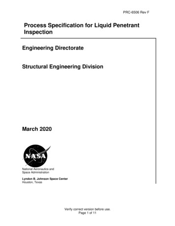
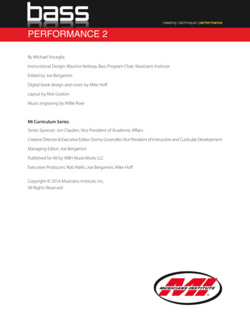
For both methods, evaluation and qualification ofsystems, the control of incoming materials, the in-processcontrol, the qualification of the inspectors and theapplicable inspection standards are primordial to achievethe best results.In the present paper, the qualification of penetrant andmagnetic particle systems was performed comparatively.The testing process described in internationalspecifications was followed providing the bestdetectability of defects in standard specimens. Optimumvalues of the main characteristics of the processesinvolved were predefined.2 FPI Penetrant Systems QualificationIn order to maintain the integrity of a penetrantprocess, the process as a whole and the individualcomponents of the system are regularly checked to ensurethat they meet the required standards. Thus, the in-usepenetrant system overall performance is being dailychecked using the same standardized test panels,according to ASTM E 1417. The comparison is madeusing photographs of initial (previously) obtainedindications using the master panels and unused material(an example is given in Figure 1). When the performanceof the in-use materials falls below the performance of theunused materials, the in-use materials are further checkedprior to conducting any penetrant examinations on realparts. The same procedure was used in order to qualifyfresh penetrant systems, comprising penetrant, emulsifier(if used) and developer. The qualification was performedby processing standardized test panels with known defects(PSM type) at the appropriate processing parameters.These standardized panels are made of stainless steel thatare chrome plated on one half and surfaced finished on theother half to produce the desired roughness (forrinsability/removability check). The chrome plated sectionis impacted from the back side to produce a starburst setof cracks. There are five impacted areas to produce rangeof crack sizes (Figure 1).Figure 1 Initial system capability test of a calibrated testpanel PSM-5 upon receipt. Penetrant Type I(fluorescent), Method D, sensitivity Level 4 (ultra-high),form a (dry developer)For the present study two water washable penetrantsystems of the same sensitivity, Level 3 (high) (SYSTEM2: Method A), as well as one lipophilic post-emulsifiedpenetrant system (SYSTEM 3: Method B) and onehydrophilic post-emulsified penetrant system (SYSTEM4: Method D) were compared. Standard test procedureper ASTM E 1417 was applied. Non-aqueous wetdeveloper is used (form d), which is generally recognizedas the most sensitive when properly applied [1].Conditions of the test are given in Table 1.Table 1 Test ParametersDwell time minimum: 10min. @ 30 ºCWater temperature 28 CWater pressure: 40 psi (275 kPa)Drying @ 65 ºCExamination under UV light, min 1200 μW/cm2 @ 30 cmEvidence of proper PT system performance can beassessed when the minimum number of indications in thetest panel is visible under black light inspection for thespecific sensitivity level of penetrant being used. It has tobe noted that each indication shall be measured to assurethat its longest dimension under UV illumination meetsthe requirements shown in Table 2. It was verified thatthe size of the indications shall be within 20% of thesize measured from the master panel.Table 2 PSM panels artificial discontinuities min sizeArtificialMinimum Diameter SizeDiscontinuity(mm)ANo size limitB1.1C1.9D3.2E4.6For the overall working PSM panels at HAI theminimum number of crack centers for each sensitivitylevel shall be as in the Table 3 below per an internal HAIProcess Specification, which comprises customerscontrol testing requirements.The results are presented in the Figures 2-4.Table 3 Min detectable number of cracks per FPI Method- Level (sensitivity)MinimumSystemMethod - Levelnumber ofcrackcenters1234A-2A-3B-3D-34444
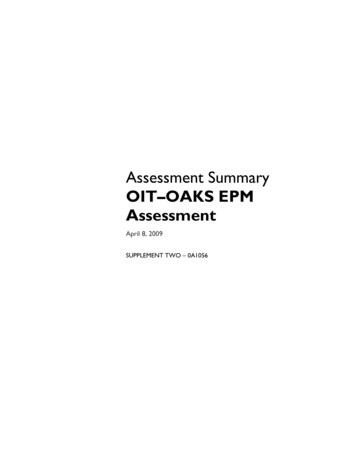
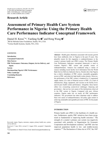
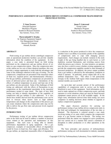
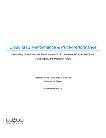
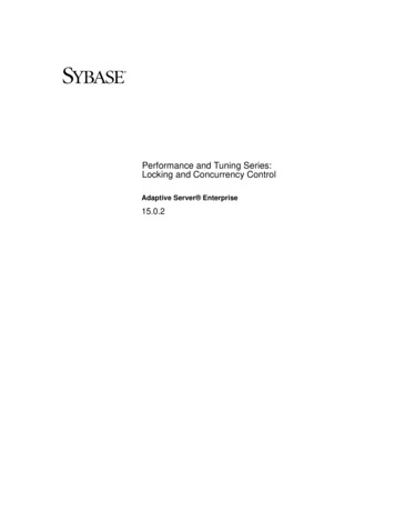
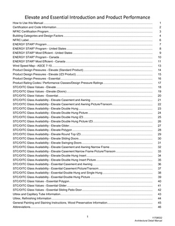
5D-45Figure 4 Results on PSM panel for lipophilicpostemulsifiable penetrant emulsifier; system3: Method B, Level 3, form dAfter each use, all penetrant and developer residuesare cleaned by ultrasounds and the panels are storedsubmerged in protected dry envelope to minimizedegradation. In addition, each test panel is annually sentoff to the supplier for thorough cleaning, crackmeasurement and calibration.3 Magnetic Particle Testing MaterialsQualificationFigure 2 Results on PSM panel for waterwashable systems 2 (Method A, Level 3, form d)Figure 3 Results on PSM panel for hydrophilicpostemulsifiable penetrant remover; system 4:Method D, Level 3, form dTwo magnetic particles systems (Wet MethodFluorescent, magnetic particles in suspension) werecompared in wet horizontal magnetic particle equipmentin which the suspension is retained in a reservoir and recirculated for continuous use. One system is suspended inwater and the other in light petroleum, and they are bothfluorescent ready-to-use at a given concentration andboth are applied to the test surface by pouring. Whenwater is used as a suspension for magnetic particles itshall be conditioned suitable to provide for properwetting, particle dispersion and corrosion protection.Both wet particles meet the requirements of AMS 3045(Magnetic Particles, Fluorescent, Wet Method, OilVehicle, ready-to-use).Proper wetting is determined by water break test.Operating temperature was 280C. The viscosity of theliquid vehicles used is kept below 5cSt (5 mm²/s) toobtain optimum results. The particles concentration in thetest bath was measured to be 0.15 ml.The comparison and the performance tests were carriedout using a Ketos Ring, as described in ASTM E1444(Figure 5) and the following methodology: Theconductor is placed with a diameter between 25 and 31mm and a length longer than 40 cm through the center ofthe ring. The Ketos ring is placed on the length of theconductor. Magnetization is applied to the ring circularlyby passing the current specified in Table 3 through theconductor. The wet suspension is poured to the ring usingthe continuous method. Examination is followed within 1min after current application (examination of fluorescentbaths was conducted under a black light of not less than1200 μw/cm²). The numbers of hole indications shallmeet or exceed these specified in Table 4.Results are given in Figure 6.Table 4 Required Indications When Using the KETOSRing Specimen of Figure 5Particles Wet suspension,1400325005Fluorescent34006
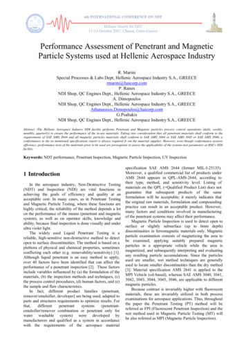
Figure 5 Manufacturing details of a Ketos Ring perASTM E 1444Figure 6 MPI comparative results for two different MPsystems4 Discussion of resultsThe selection of a liquid penetrant system is not astraightforward task. Many factors must be consideredwhen selecting the penetrant materials [penetrant,remover/emulsifier and developer] for a particularapplication.As described in section 2, two FPI commercialproducts of the same Method A (water washable) werecomparatively investigated using the standard PSMpanels. As shown in Figure 2, the performance of the firstone is slightly better that the second, by clearly revealingthe 5 defects, whereas the indications of the second oneare blurred. It has to be also mentioned that under thesame process parameters the washablility (penetrantremovability) of the later was inferior (penetrant residuesin the lower part (rough part) of the panel).Another consideration in the selection of a penetrantsystem is whether water washable, postemulsifiable orsolvent removable penetrants will be used.Postemulsifiable systems are designed to reduce thepossibility of over washing, which is one of the factorsknown to reduce sensitivity. Solvent removablepenetrants, when properly used, can have the highestsensitivity, but are usually not practical for large-areainspection or high-volume production. In Figures 3 & 4the results of a hydrophilic penetrant/remover system anda lipophilic penetrant/emulsifier were given respectively.Considering the Figures 2, 3 & 4 the higher sensitivity ofthe postemulsifiable hydrophilic penetrant can beconcluded.Figure 6 depicts the results of two different MPIsystems under the same parameters using the Ketos ring;only in the first one (oil based vehicle) the maximumnumber of holes can be seen.The influence of various process parameters upondetectability of defects in penetrant testing has beeninvestigated by both researchers and productmanufacturers [2] [4] [5] [6]. An earlier method, referredto as “Two Fold Congruency test”, has been developedby Pratt & Whitney to screen penetrants for sensitivityand reproducibility [7]. This test, performed on controlledparts in the laboratory, statistically evaluates indicationsfound by each penetrant against a standard. Visionsystems and computed algorithms were used to quantifythe results of penetrant testing along with operatingparameters [8] [9]. The developed methodology(software equipment) allows a quantitative evaluation ofdefect indications by its optical and geometricalcharacteristics correlated to the physical undergoingprocesses. These methods and equipment could be apossible solution to assess the quality of a new productfamily used in PT or MT inspection.5 ConclusionsIncreased knowledge of surface chemistry, newchemical compounds and improved methods offormulation have resulted in the development of mainlypenetrant systems, and to a lesser content magneticparticle systems, with increased sensitivity and flawdetection capabilities. Although quality assuranceprovisions are required from material manufacturers, asdescribed in the
per ASTM E 1417 was applied. Non-aqueous wet developer is used (form d), which is generally recognized as the most sensitive when properly applied [1]. Conditions of the test are given in Table 1. Table 1 Test Parameters Dwell time minimum: 10min. @ 30 ºC Water temperature 28 C Water pressure: 40 psi (275 kPa) Drying @ 65 ºCFile Size: 348KBPage Count: 5