Transcription
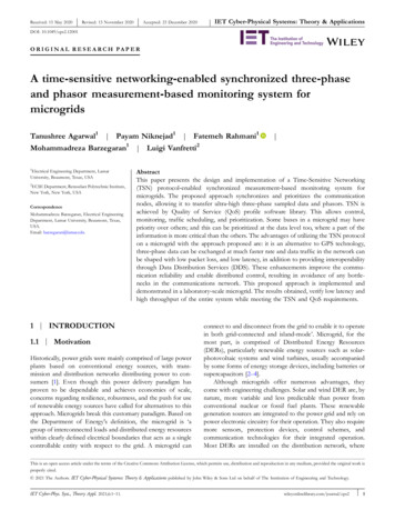
Received: 15 May 2020- - Revised: 13 November 2020Accepted: 23 December 2020IET Cyber‐Physical Systems: Theory & ApplicationsDOI: 10.1049/cps2.12001O R I G I N A L R E S E A R C H PA P E RA time‐sensitive networking‐enabled synchronized three‐phaseand phasor measurement‐based monitoring system formicrogridsTanushree Agarwal1 Payam Niknejad1 Fatemeh Rahmani1Mohammadreza Barzegaran1 Luigi Vanfretti21Electrical Engineering Department, LamarUniversity, Beaumont, Texas, USA2ECSE Department, Rensselaer Polytechnic Institute,New York, New York, USACorrespondenceMohammadreza Barzegaran, Electrical EngineeringDepartment, Lamar University, Beaumont, Texas,USA.Email: barzegaran@lamar.edu. AbstractThis paper presents the design and implementation of a Time‐Sensitive Networking(TSN) protocol‐enabled synchronized measurement‐based monitoring system formicrogrids. The proposed approach synchronizes and prioritizes the communicationnodes, allowing it to transfer ultra‐high three‐phase sampled data and phasors. TSN isachieved by Quality of Service (QoS) profile software library. This allows control,monitoring, traffic scheduling, and prioritization. Some buses in a microgrid may havepriority over others; and this can be prioritized at the data level too, where a part of theinformation is more critical than the others. The advantages of utilizing the TSN protocolon a microgrid with the approach proposed are: it is an alternative to GPS technology,three‐phase data can be exchanged at much faster rate and data traffic in the network canbe shaped with low packet loss, and low latency, in addition to providing interoperabilitythrough Data Distribution Services (DDS). These enhancements improve the communication reliability and enable distributed control, resulting in avoidance of any bottlenecks in the communications network. This proposed approach is implemented anddemonstrated in a laboratory‐scale microgrid. The results obtained, verify low latency andhigh throughput of the entire system while meeting the TSN and QoS requirements.1 INTRODUCTION1.1 MotivationHistorically, power grids were mainly comprised of large powerplants based on conventional energy sources, with transmission and distribution networks distributing power to consumers [1]. Even though this power delivery paradigm hasproven to be dependable and achieves economies of scale,concerns regarding resilience, robustness, and the push for useof renewable energy sources have called for alternatives to thisapproach. Microgrids break this customary paradigm. Based onthe Department of Energy's definition, the microgrid is ‘agroup of interconnected loads and distributed energy resourceswithin clearly defined electrical boundaries that acts as a singlecontrollable entity with respect to the grid. A microgrid canconnect to and disconnect from the grid to enable it to operatein both grid‐connected and island‐mode’. Microgrid, for themost part, is comprised of Distributed Energy Resources(DERs), particularly renewable energy sources such as solar‐photovoltaic systems and wind turbines, usually accompaniedby some forms of energy storage devices, including batteries orsupercapacitors [2–4].Although microgrids offer numerous advantages, theycome with engineering challenges. Solar and wind DER are, bynature, more variable and less predictable than power fromconventional nuclear or fossil fuel plants. These renewablegeneration sources are integrated to the power grid and rely onpower electronic circuitry for their operation. They also requiremore sensors, protection devices, control schemes, andcommunication technologies for their integrated operation.Most DERs are installed on the distribution network, where-This is an open access article under the terms of the Creative Commons Attribution License, which permits use, distribution and reproduction in any medium, provided the original work isproperly cited. 2021 The Authors. IET Cyber‐Physical Systems: Theory & Applications published by John Wiley & Sons Ltd on behalf of The Institution of Engineering and Technology.IET Cyber‐Phys. Syst., Theory Appl. 2021;6:1–11.wileyonlinelibrary.com/journal/cps21
2-there is an absence of effective communication, monitoring,and control infrastructure in its existing state. Thus, this underlines the need for a monitoring and communication systemto enable microgrid operation that meets stringent communication network requirements, including security, reliability, latency, bandwidth, and most importantly, interoperability(specifically in terms of adding more devices from any vendor).Such a monitoring system would improve grid performanceand efficiency significantly, but also brings complexity to theintegrated system design and analysis [5–9].To address these complexities, develop functionalities, andanalyse their performances, a hardware/software smart gridtestbed infrastructure can be used. This testbed needs tosupport the necessary hardware and software environments toperform different experimental scenarios in real time [10].1.2 Literature reviewSeveral microgrids that include hardware and software testbedshave been developed. The hardware structure consists ofgenerators, transmission lines, storage devices, power electronic converters, and loads. The software includes communication and information technologies. However, there is aneed to provide the tools and interfaces to integrate severalplatforms into a scalable system that is expandable and open tonew services, components, and operation scenarios. This oftenleads to a high cost hardware, ad hoc software customization,and highly trained staff requirements. To address some of theseproblems, middleware can be used [11].In this context, a middleware can offer common servicesand ease of software application development by integratingheterogeneous computing and communication devices andsupporting interoperability within the diverse applications andservices running on heterogeneous devices. These could evenreside on the physical devices themselves and provide thenecessary functionalities to enable service deployment [12].The communication middleware is a crucial part of themicrogrid testbed. It provides an abstraction layer that simplifies communication amongst the nodes irrespective of theunderlying hardware architecture [13,14]. A good middlewarealso provides a standard Application Programming Interface(API) that helps in multiple and diverse use cases. Thecommunication middleware can be classified into two subcategories: message centric and data centric. The data‐centricmiddleware technique is used more often because it has moreadvantages over the message‐centric technique. For example, itis more flexible, more reliable, and less prone to errors. It alsoutilizes the network bandwidth more efficiently [15–17].1.3 ContributionsThe research presented exploits a data‐centric approach toaddress some of the challenges described above. It is implemented on the Data Distribution Services (DDS) technologyfrom Real‐Time Innovation (RTI). DDS is an openAGARWALET AL.communication protocol that is used to implement Machine‐to‐Machine (M2M) communication and information exchange.This framework allows to deploy real‐time communication andinformation exchange system that is based on the publisher‐subscriber concept and supports peer‐to‐peer communication.Applying Quality of Service (QoS) profiles using DDS distinguishes the proposed approach from other communicationmethods. Different QoSs can be applied for different datatypes making the framework agile and convergent, and thus itcan be leveraged to deploy different communication and information exchange mechanisms that have a sense of time,prioritization, and synchronization. These capabilities allow tomeet Time‐Sensitive Networking (TSN) requirements. Thecontributions of the proposed microgrid monitoring andcommunication platform can be summarized are: To provide synchronization by offering a common timereference to all the nodes in the network, as an alternate toor in conjunction with Global Positioning System (GPS)technology. To provide prioritization of three‐phase data and phasordata at the nodes from which data is collected. To provide a sense of time, making it time‐critical in realtime, by meeting TSN requirements, through QoS profiles. To enable interoperability, that is devices from any vendorand manufacturers integrated into the proposed frameworkcan be used when adopting the DDS standard To provide means for network traffic shaping so to avoidbottlenecks through QoS profiles. To provide low latency and high throughput required formicrogrid functions through QoS profiles. To provide experimental evidence on the implementation ofthe proposed approach in a laboratory‐scale microgridtestbed.The remainder of this paper is organized as follows: Section 2 describes different microgrid monitoring systems, theirshortcomings, and how the proposed TSN‐enabled approachcan be a viable alternative. Section 3 is the proposed system,that is a TSN‐enabled synchronized three‐phase and phasormeasurement‐based monitoring system for microgrids. Section 4 presents the experimental validation, detailing each partof the testbed and hardware used. Section 5 depicts the resultsobtained using the experimental setup. Finally, Section 6 concludes the major findings of this work.2 MICROGRID MONITORINGSYSTEMSMicrogrids are smaller in size and posses a number of assetswhen compared with the existing power grids, and communication networks are becoming a vital part for their operation[18] as they may need to operate in two different modes: power‐grid connected or standalone. Extensive research has beenconducted and several methods are used for monitoringmicrogrids. Conventionally microgrid monitoring is static and
AGARWAL-ET AL.in non‐real time, resulting in additional time for acquiring themicrogrid's response when operating in dynamic conditions[19]. These are well‐known challenges in systems where Supervisory Control and Data Acquisition (SCADA) is widelyused.2.1 SCADAA SCADA system supervises, controls, and regulates themicrogrid. It acquires data at regular intervals by polling fielddevices asynchronously. The polling rates are 1 3 s, resultingin time‐skewed measurements with limited information. Othershortcomings of this monitoring system include the type ofdata collected is scalar and depend on power network modelsto derive additional information like the phase angle via a stateestimator. A major drawback arises from the way data iscollected that is non‐coherent and a missing common timereference. This power grid monitoring system, that is SCADA,although sufficient for the operation of most of the powertransmission grid infrastructures, is generally consideredinsufficient to meet the monitoring requirements while operating on the status of the newly emerging distributed powersystems and microgrids.2.2 PMUPhasor Measurement Units (PMUs) have emerged as a solution to the above stated problems associated with SCADAsystems [20]. While some use cases are arising for distribution networks [21,22], they are mainly used in real‐worldapplications only in transmission grids [23] and so far, theyare not common for microgrids, but they may enable criticalmicrogrid functions [24,25]. PMUs measure the phasorvoltage and current of the field devices deployed. They allhave a common time reference provided by the GPS technology, and they are also known as Synchrophasors due tothis reason. Synchrophasors provide high‐speed coherentdata. PMU reporting rates vary from 30 to 120 samples/s byproviding an alternative to SCADA. Figure 1 shows a conceptual PMU‐based microgrid monitoring system contrastedwith a conventional power grid PMU‐based monitoringsystem.Analysing Figure 1, significant challenges arise whenconsidering the use of PMUs for a microgrid monitoringsystem, which have been revealed in the experience withtransmission grid applications [26]: Poor data quality: due to poor synchronization of timingmeasurements [27]. Communication: latency, network congestion, and failure ofcommunication nodes [28]. Aggregator: Data transformation may result in errors,delayed arrival of packets dropped due to exceeding timelimits, and unwanted duplication or corruption of dataduring computations, while increasing the overall latency [1].3 GPS issues: Although GPS signal that is widely used incurrent Synchrophasors can provide a sub‐microsecondtiming accuracy, there exist geographical constraints andsignal limitations, and GPS can be subject to spoofing attacks [29].A direct implementation of PMU technology in microgridis therefore not advisable, as the conventional approach todeploy the communication infrastructure is not scalable;however, it is expensive and inflexible. This article proposes analternative approach to leverage the advantages of PMUs, whilemitigating the limitations outlined above.To leverage situation awareness and support timeliness,adequate quality checking methods must be in place. Thisarticle proposes an approach that meets these requirements byenabling TSN capabilities, that can be used for microgridmonitoring using PMUs or even ultra‐high sampling rate three‐phase measurements.2.3 TSNTSN is the advancement of the standard Ethernet, particularlythe IEEE 802.1AS standard that suggests time synchronizationof devices utilizing packet transfer over Ethernet. This helps intraffic scheduling and system configuration thus enablingdeterministic communication over the Ethernet by allowingusers to schedule time‐critical data across a network [30,31].IEEE 802.1AS is an IEEE 1588 profile that provides a common time reference to all the nodes within the IEEE 802.1ASsubnet, hence providing an alternative to the GPS‐based synchronization while simultaneously being part of the dataconnectivity (network) of the system. It synchronizes multipledevices using packet‐based communication and makes itpossible over long distances without any signal propagationdelay impact. I/O synchronization on devices using this profileis less than 1 μs [32,33].Because it is based on open standards, TSN can beimplemented in different ways for different applications. TSNfacilitates: Time synchronization: All devices share a common timereference and can synchronize with each other by synchronizing internal time signals with respect to thatreference. Traffic scheduling: Adding mechanisms to ensure that information is delivered with a certain level of determinismfor real‐time communication without disrupting thecurrently existing prioritization mechanisms of non‐TSNEthernet. System configuration: Standardizing the parameters forconfiguration such as reservation of communication paths,time slots, and bandwidth to handle fault‐tolerance andmission‐critical information transfer. Priority scheduling: To schedule priority traffic amongdifferent end devices and switches with a shared notion oftime.
4-FIGURE 1FIGURE 2devicesAGARWALET AL.A conceptual PMU‐based microgrid monitoring system and a traditional power grid PMU‐based monitoring systemA data packet is transmitted between two TSN‐enabledIn a TSN‐enabled network, each transmission link has aschedule that includes flow IDs, Transmission offsets, andexpected payloads. Figure 2 shows the data packet beingtransmitted between two TSN‐enabled devices, where T is thetotal time taken between devices. There are N periods, andwithin each period there are three slots. Slot 1 that is yellow incolour presents TSN packet reservation containing high priority data, followed by white slot that acts as a transition between slots 1 and 3 and avoids any overlap. Slot 3, in green, isthe best effort packet that avoids repetition and data duplicityin the network.While PMUs have been used at the transmission level, tosynchronize voltage and current phasor estimates, theembedded controllers used for power electronics and invertercontrol are usually not time synchronized. The same applies toother controllers and data acquisition systems that are part ofthe power grid.With the augmentation of the TSN capabilities to amicrogrid, synchronization can be attained. It ensures thatnodes of a microgrid derive their acquisition or generationtiming from the same source. In the absence of proper synchronization, there is no way to know if two measurementshappened simultaneously or, in the case of stimulus/responsetype testing, which stimulus the measurement is a response of.TSN provides the basic infrastructure for synchronization anda common time reference to all devices in the microgrid, whilealso providing traffic scheduling and system management capabilities [34–36].All these are important in any smart grid and/ormicrogrid systems where data exchange between devices mustbe correctly time‐stamped and arrive at its destination withina specific timeframe with minimum jitter. Most advancedcontrol algorithms can take advantage of this capability indistributed systems where a unique time reference anddeterministic communication between devices may enable theimplementation of such concepts as multi‐agent controlsystems while simultaneously improving the observability ofthe system.The authors’ previous work [37] presents the design andimplementation of a multi‐level TSN protocol based on areal‐time communication platform utilizing DDS middleware.The performance of the developed protocol was tested andvalidated using data replay in real‐time, that is replaying thevoltage and current three‐phase waveforms and phasors of awind farm within different case scenarios. Satisfactory resultswere obtained for latency and throughput parameters of TSNat high message rates at the sampling rate of 100K samplesper second. In this article, previous work is leveraged toenable a complete microgrid monitoring system and todemonstrate its feasibility in a laboratory‐scale microgridenvironment.
AGARWAL-ET AL.3 PROPOSED TSN‐ENABLEDMONITORING SYSTEM FORMICROGRIDS To achieve synchronization, traffic shaping, prioritization, andscheduling on a microgrid, a TSN‐enabled synchronized three‐phase and phasor measurement‐based monitoring system formicrogrids is proposed and implemented in a laboratory‐scaletestbed. The proposed system is composed of two layers: ahardware layer for data acquisition and processing, and a virtualization layer for deploying TSN‐enabled networking, asshown in Figure 3.Figure 3 shows the general approach towards the monitoring system for microgrids, where it is bifurcated into thehardware layer and the virtual layer. The implementation of thehardware layer involves not only the hardware components forsignal acquisition, but also the electrical components thatcomprise the microgrid, that is renewable energy sources suchas photovoltaic (PV) panel, wind turbine, and microturbinealong with a battery‐based energy storage system, transmissionline emulators, and alternate current (AC) and direct current(DC) loads are considered. All nodes use the virtual layer forsending the data through a common DDS data bus based on aTSN protocol.In the sequel, only the hardware components related tocommunications are described because they are crucial for theproposed design in this article, while the power componentsare generic; the proposed virtualization layer is also discussedin detail.3.1 Hardware layer for data acquisition andprocessingThis layer can further be divided into data acquisition andcommunication components. Data acquisition: The data is acquired from different nodes.This measurement can be a phasor or three phasedepending on the type of node and measurement equipmentFIGURE 3Proposed microgrid monitoring system architecture 5available. The key to these measurements taken, lie indeterminism that is the shared concept of time. To implement, the same TSN system is used.TSN system components: There are five main componentsin the TSN system.TSN flow: This is the time‐critical communication betweenthe nodes or devices. It follows a fixed time protocol thatevery device in the network follows.Nodes: these are the devices that follow the deterministiccommunication. They are also referred as subscribers(receivers) and publishers (senders).TSN switch: They act as a bridge capable of transmittingand receiving data frames of a TSN flow for a predetermined schedule.Central network controller: As the name suggests, it controls the TSN switches in the network. It is a softwareapplication running on different nodes. It has two mainresponsibilities. First, determining the route and schedulingthe TSN flow through the network and second. configuringthe TSN switches for TSN operation.Centralized user configuration: An application that communicates between Central Network Controller and thenodes. It makes requests for the TSN flow and its pre‐requisites.3.2 Virtualization layerThe communication network requires peer‐to‐peer communication and the nodes are in direct contact with each otherwithout the third‐party intervention. The virtualization layershould abstract complex network details like network topologyand nodal information and provides a simpler interface. DDS: The DDS middleware works on a data‐centricapproach publisher‐subscriber model and focuses mainly onthe algorithm and control method. The standard API for theDDS middleware provides the necessary tools to integratewith different simulation and analysis software with thesupport of several programming languages such as C, C ,and JAVA. Microgrids need low data latency to support fastcontrol actions and maintain stability. TSN offers a widevariety of QoS profiles to meet different needs of controllers and data types. QoS Profiles: TSN is aware of data types and the priority ofeach data type. For this purpose, a new library of QoSprofile is created to control the data exchange. This featurehelps to achieve the TSN capabilities for the network. TheQoS policy defines a distinct set of rules that control howthe data will be sent and handled by the infrastructure. Toattain the TSN features in the network, multiple profileswere developed and assembled in a library.The QoS profile library developed for this work is thecentral component for a complete QoS model. The design ofthe profiles is explained as follows. The time synchronizationfeature of TSN is fulfilled when all publishers or subscribers
6-belong to the same domain and, being the domain participants,share the same time reference. For traffic scheduling, prioritization, and system configuration (path reservation, bandwidth,time slots), scheduling policies such as Round Robin (RR),Earliest Deadline First (EDF), and Highest Priority First(HPF) are utilized. The EDF is used for the proposed modeland QoS library. In this policy, priority can be decideddynamically based on the latency budget and the deadline.Hence, it is ensured that the data packet is neither lost nordelayed.There are two separate profiles for defining latency andthroughput in the library which help in prioritizing the latency‐sensitive data. For the TSN, there is a need for low latencybudget. A time period is specified within which the information must be distributed. This time period starts from themoment the data is written by the publisher until it is availablein the subscriber's data cache ready for use by the readers. Thethroughput profile also helps in defining maximum throughputand preventing peak bursts. A library is created by utilizing thelisted QoS profiles and it is implemented on the proposedTSN‐enabled microgrid.4 EXPERIMENTALIMPLEMENTATIONTo implement the proposed TSN‐enabled synchronized measurement‐based monitoring system for microgrids, the standalone laboratory‐scale microgrid is shown in Figure 4. It isdeveloped based on the concept of Figure 3.Figure 4 illustrates the typical scheme of the intendedmonitoring system including the TSN implementation framework and the data acquisition hardware. Each part of thesystem is explained individually in the next subsections.4.1 Data acquisitionThe data which is the three‐phase voltage or phasor voltageconsisting of frequency, amplitude, and phase, is collected fromdifferent nodes of the microgrid that is nodes #1–5 having thesame time reference. The data is acquired using the BeagleBone‐Black (BBB) from each node. BBB is a low‐cost development board featuring the AM3358 ARM Cortex‐A8 processor from Texas Instruments.Four important nodes (nodes #1, #2, #3, and #5) areselected for monitoring purpose with a BBB based datacollection unit at each node. The advantage of the BBB for thisapplication is the existence of two ‘Programmable Real‐timeUnits’ (PRUs) which are two separate reduced instruction setscomputing CPUs on the same silicon die as the main ARMCPU, with separate data and instruction memories whilesharing the same data bus. The PRUs are clocked at 200 MHzand have access to pins, events, and hardware resources on thesystem‐on‐chip, so they can be tasked with hard real‐timefunctions. They can be given a function to do that whichoperates independently of the operating system on the mainAGARWALET AL.CPU; thus the typical causes of delays that would interfere witha real‐time process are eliminated, while data can be sharedbased on the same memory map between ARM Linux andPRUs.The data is acquired from nodes #1, #2, #3, and #5. Thisdata is transmitted to the master controller through both wiredand wireless connections. Nodes #1, #2, and #3 are wired,whereas node #5 sends data wirelessly. For the wirelesscommunication, Xbee‐S2 is chosen. To ensure that the acquired data is not distorted during wireless communication,Butterworth low pass filter (LPF) of order 2 is used with anamplifier circuitry as shown in Figure 5.4.2 TSN systemAfter the data is acquired, it is received in the TSN system,Cisco IE‐4000. It supports delay‐sensitive applications andtime‐sensitive networks. It has the capability to support upto eight devices and the bandwidth and capacity of 20‐Gbpsnon‐blocking switching capacity with up to 20‐GB Ethernetports per switch. It consists of a 1GB DRAM, a 128‐MBonboard flash memory, a 1‐GB removable SD flash memory card, a mini‐USB connector, and RJ‐45 connector.Figure 6 depicts the PV, battery bank, bidirectional DC‐ACconverter, and the TSN system and PXIe connection. TheCisco IE‐4000 system benefits from a robust design anduser‐friendly GUI which allows easy configuration andmonitoring.4.3 AggregatorThe network of TSN‐enabled nodes is monitored by onemaster controller NI PXIe system which can acquire dataand running models in real time (deterministically) and inparallel. The software required to do so is a combinationof NI‐LabVIEW and MATLAB/Simulink. The modelselected is NI PXIe‐1073 chassis with the NI PXIe‐6356card.Because voltage amplitude, phase angle, and frequency,which are all AC parameters, are considered as the main inputdata of the TSN‐based condition monitoring system, the fiveAC nodes of this microgrid are considered as the data subscribers, while the main microgrid monitoring and controlcentre, located at a separate location, is the publisher. The DCvoltage level and battery's State of Charge (SOC) at node #0can be also collected and transmitted to the monitoring centreas additional inputs that might be helpful for microgridoperation and in decision‐making during adverse incidents orpeak hours.4.4 Electrical network setupThe experimental setup of the lab‐scale microgrid of Figure 4,is designed and implemented in the Lamar Renewable Energy
AGARWAL-ET AL.FIGURE 4FIGURE 5controller7Prototype implementation of the microgrid monitoring systemWireless connection between node #5 and the masterand Microgrid Laboratory at Lamar University. The wind energy system is emulated by using a three‐phase MJB160XA4208 V 11.8 kW 60 Hz synchronous generator driven by WEG15HP 208 V 60 Hz three‐phase induction motor controlled byESV752N06TX Lenz variable frequency drive to apply realwind speed and emulate the wind turbine. The same motor‐generator configuration with a fixed supply voltage of 208 V60 Hz is used to emulate the microturbine. Figure 6 shows thisemulator.As shown in Figure 7, an Intertek 4002316 PV panelincluding a 4 9 array of PV modules with open circuitvoltage and short circuit current of 21.06 V and 8.62 A isutilised as a PV source. The energy storage system includes five12 V 8 A batteries in parallel connected to the DC node. Abidirectional buck‐boost converter consisting of 600 V 23 AIRG4PC30UDPBF IGBTs, 600 V 15 A ISL9R1560G2 diodes,WE‐SD 20A 15 μH inductor, and a 250 V 100 μF capacitor isdesigned and built to connect the DC node #0 to the AC node#1. To control the converter, the output voltage is sensed withthe LEM LV25‐P voltage transducer and sent to the LabVIEWcontroller through NI PXIe‐6356 data acquisition device andthe 10 kHz PWM pulses are created for the Microchip Technology MCP1406 IC to drive the IGBT as shown in Figure 7.AC and DC loads are implemented through resistive‐inductive 50–400 W units. The loads are connected to thenodes through solid state relays to be able to turn them ON orOFF through the monitoring panel.5 EXPERIMENT RESULTSThe TSN protocol is tested by considering a scenario wherenodes #1, #2, #3, and #5 are active. The data from thesenodes is either three‐phase voltage or phasor voltage, which
8-AGARWALET AL.FIGURE 6The configuration used toemulate wind turbine and microturbineManifold Subscriber (MPMS), this is the complete implementation of the TSN protocols at all three levels that is atpublisher level (level I), subscriber level (level II) and the datalevel (level III). As the name suggests it has manifold publishers, and manifold subscribers may or may not have multipledata packets. Also it is important to note that subscribers arenot bound to receive data from every publisher in the network,rather its optional and flexible.Two profiles are discussed and compared below. The firstone is the OPOS and the second one is a ty
1Electrical Engineering Department, Lamar University, Beaumont, Texas, USA . New York, USA Correspondence Mohammadreza Barzegaran, Electrical Engineering Department, Lamar University, Beaumont, Texas, USA. Email: barzegaran@lamar.edu. . Theory & Applications published by John Wiley & Sons Ltd on behalf of The Institution of Engineering and .