Transcription
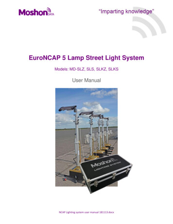
EuroNCAP 5 Lamp Street Light SystemModels: MD-SLZ, SLS, SLKZ, SLKSUser ManualNCAP Lighting system user manual 181113.docx
LEGAL NOTICEInformation furnished is believed to be accurate and reliable. However, Moshon Data Limitedassumes no responsibility for the consequencies of use of such information nor for anyinfringement of patents or other rights of third parties which may result from its use. No license isgranted by implication or otherwise under any patent or patent rights of Moshon Data Limited.Specifications mentioned in this publication are subject to change without notice and do notrepresent a commitment on the part of Moshon Data Limited. This publication supersedes andreplaces all information previously supplied.Copyright notice Copyright 2018, Moshon Data Ltd.RevisionDocument Revision: MD181113 (See revision history for detailed information).Contact DetailsMoshon Data Ltd33 South LawnWitneyOxfordshireOX28 5HYEnglandPhone: Tel: 44 1993 209098Web: http://www.moshondata.comEmail: info@moshondata.comNCAP Lighting system user manual 181113.docx
CONTENTSLegal notice . 2Introduction . 3Scope of Delivery . 4Overview of System . 4Specifications . 5Q-POD . 5MD-Base . 8Mast Attachment . 9Luminaire fitting and usage . 11Cabling Diagram . 14Taking light readings . 15Mast Overview . 16Mast Raising procedure . 17Mast Lowering procedure . 18Mast maintenance notes . 19INTRODUCTIONThank-you for choosing Moshon Data.The NCAP lighting system is a complete 5-streetlamp system designed and tailored specificallyfor the NCAP AEB VRU night testing procedure.Moshon Data has worked very closely with both lighting and mast manufactures to create alighting solution that provides everything you need to start testing from the day of delivery.Additional models have been created (MD-SLKZ, MD-SLKS) to provide the user with exactingdegree alignment of the masts using a turnable, keyed mast.Bases for the masts can be chosen to have either a mobile 4 wheeled base (MD-Base), or a QPod tripod.This manual covers the installation, cabling, raising and lowering procedure for the full system.NCAP Lighting system user manual 181113.docx
SCOPE OF DELIVERYAll MD lighting system products are supplied complete with cables, manuals, adapter fittings etc.Everything you need to start night testing.QtyDescription5Schuch or Zeta luminaire fitting and cable5Pneumatic mast (Keyed or standard)5Nylon head Adapter plate – allows fitting of luminaire to mast head5Q-Pod or MD-Base*13 Way 16A splitter22 Way 16A splitter110 m high quality HO7RN-F rubber cable.425 m high quality HO7RN-F rubber cable.10Q-Pod Weight bags* (Not applicable if MD-Base is supplied)*With the exception of sand and concrete for the weight bags and 4 wheeled bases.Not included for logistical reasons - will drastically reduce shipping and handling costs.Where an MD-Base is supplied, it will be neccesary to fill the shell with concrete before use.Instructions on how to do this are in this manual.OVERVIEW OF SYSTEMThere are four models offered by Moshon data. These are shown in the table below.ModelMD-SLZMD-SLSMD-SLKZMD-SLKSLuminaire headMast typeBase typeZeta SmartScape NanoSchuch 48 2403 ABX CLZeta SmartScape NanoSchuch 48 2403 ABX CLStandard PneumaticStandard PneumaticKeyed PneumaticKeyed Pneumatic4 wheel MD-Base or Q-pod4 wheel MD-Base or Q-pod4 wheel MD-Base or Q-pod4 wheel MD-Base or Q-podNCAP Lighting system user manual 181113.docx
SPECIFICATIONSParameterLuminaire powerLuminous eficacyLuminous fluxAmbient temperatureInput VoltageIP Water Ingress RatingMaximum wind speedresistanceMD-SLZMD-SLSMD-SLKZMD-SLKS8-50 W140 lm/W(@42 w)-20 - 45 C240 or 24 VIP66 (head)IP44(connectors)56 mph49 W121 lm/W8-50 W140 lm/W49 W121 lm/W5200 lm240 VIP66 (head)IP44(connectors)56 mph-20 - 45 C240 or 24 VIP66 (head)IP44(connectors)56 mph5200 lm240 VIP66 (head)IP44(connectors)56 mphQ-PODThe deployment of the Q-Pod ready for mast attachment is as follows.NCAP Lighting system user manual 181113.docx
Pull out the main central leg to release the other three legs from achor pointPull straight the three Q-Pod feetStand Q-pod upright and turn the centre knob to locate centre pole as requiredPull down the centre column to open out the legs, and secure as shownNCAP Lighting system user manual 181113.docx
Adjustments can be made to each leg to level up the frame to the ground. To do this, use a 90deg angle measuring device such as a set square to adjust the tripod to the ground as requiredFor full stability of the mast, the final step is to hang two weight bags full of sand from eachcarabiner found at the top of the Q-PodCollapsing the Q-Pod is the reversal of above, the feet are pulled back, and tucked behind thecurved edges of the central foot to hold in place during transportation.NCAP Lighting system user manual 181113.docx
MD-BASEThe MD-Base comes to you as an empty shell – as shown lelow.The shell must be filled with concrete before first use. The concrete is a mixture of cement, sand(aggregate) and water.To do this, find a level area of ground (this is very important) then fill the structure with concreteto the very top lip.Please be VERY careful not to get cement on the four studs in each corner.Once the concrete has dried, attach the bolt down mast base to the top ond bolt down with thefour nuts supplied.NCAP Lighting system user manual 181113.docx
MAST ATTACHMENTQ-PodWith the Q-Pod deployed and adjusted level to the ground, the mast can be attached.Offer the thumbscrew at the lower end of the mast to the bottom Q-Pod slot, without loweringit fully into the slot Locate the top slot and align the top thrumbscrew on the mast to the top slot on the Q-Pod anddrop it into place. Tighten up both thumbscrews to secure. A large washer should be positionedbehind each thumbscrew.NCAP Lighting system user manual 181113.docx
MD-BaseAttaching the mast to the MD-Base is much the same as with the Q-Pod.Move to the desired position, the base should alreadybe level to the ground by design, but just check thatthis is the case with a set square.Then lock each of the wheels by pressing down thefoot lever.Lower the two support plates to the ground for extra stability.NCAP Lighting system user manual 181113.docx
LUMINAIRE FITTING AND USAGEThere are two types of luminaire offered by Moshon Data - Zeta and Schuch.The luminaire consits of the following parts: The luminaire fitting (Zeta or Schuch)Nylon adapter pole – three adjustable positionsLocating pin – long cylinder metal pinBlack thumb screwAttachmentThe luminaire head is attached to the top of the mast using the Nylon adapter plate as shownbelow.There are three possible places the steel pin (1) can be located in the Nylon pole (2), allowingadjustment of the head (3) to be made further into the test area, or away as required.Once the locating pin is in the preffered position, turn the thumb screw (4) clockwise to tightenonto the pin.(4) – Thumbscrew(1) Steel pin(2) Nylon pole(3) Head adjustmentNCAP Lighting system user manual 181113.docx
Once the locating pin is in place, drop the visible part of the pin of the luminair into the top of themast and tigiten the thumb screw (3) found at the very top of the mast, onto the steel pin (locationof thumbscrew shown only, thumb screw not visible in the image).(5) – Thumb screw(2) – Nylon adapter pole(6) – Mast thumb screwOnce tight, the cable can be routed nicely around the top thumb screw as shown.(7) – Cable routeNCAP Lighting system user manual 181113.docx
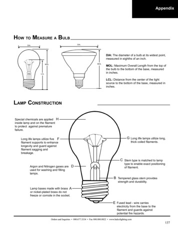
Overdrive option - Zeta onlyThe Zeta system models are capable of being adjusted to suit the light envirionment. They usean overdrive option (included by default in MD-Lighting Systems) to increase the light outputsufficiently to ensure there will be full coverage over the test area to the specification. Pleasecheck the latest NCAP protocol for the definition of what that is.To operate dimmer, remove the front panel from the control box using a standard screwdriver.Remove screws toreveal dimmer toggleWhile using a lightmeter, turn the dimming toggle up and down from 0-5 to adjust the outputluminance until it is the correct lux reading for the test.Once the correct adjustment has been made, reseal the box so that it cannot be accidentlyalterred during the test, and also to protect it from the environment.NCAP Lighting system user manual 181113.docx
CABLING DIAGRAMAll cables are supplied with the system to power up all five lights.Connectors are IP44 rated and will provide protection from intrusion of water.The diagram below shows how it all connects together.NCAP Lighting system user manual 181113.docx
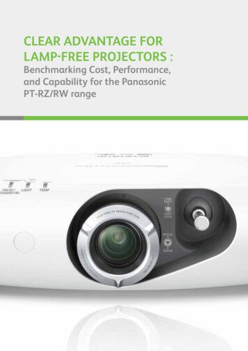
TAKING LIGHT READINGSWe recommend the use of a high quality lightmeter such as the Konica Minolta T-10A to takeeach measurement. This offers high accuracy and resolution of data, and is specified in the EuroNCAP protocol, also proved important from within our own tests at Moshon Data.Please refer to the Euro NCAP AEB VRU protocol for EPT and VUT light paths to be tested usingthe lux meter, also for the current illuminance ranges allowable for each test path.An example of a typical EPT and VUT light measurment path is shown below.VUT Path‘S’ is typically 25 m, thelight points ‘X’ are dividedequally across the testpath.EPT PathLight measure points ‘Y’ are thedivided equally between the lamp centreto VUT path distance, then onemore the other side of theVUT path.NCAP Lighting system user manual 181113.docx
MAST OVERVIEWEach mast is a very high quality tubular telescopic structure, made from stainless steel and otherhigh quality materials. It is capable of handling wind speeds up to 56 mph provided it is used asintructed with the use of sandbags etc (Based on the 6 meter 80mm diameter mast and standardlight fitting)Risks connected with the use of the mastThe telescopic mast has three main ‘risk’ conditions associated with its use. These instructionsmust be followed to assure operational safety and minimise these risks.1. The first risk is the mast falling on its side, caused by the action of wind on the mast and/orbad fixing of attached items.2. The second is related to the possibility of vertical descent of the mast, together with allappliances fixed to it.This may occur in exceptional conditions only when extending the mast, and in the caseof a major air loss, caused by a sudden malfunction of a seal, damage to the mast orproblems related to extreme temperatures. In this case it is possible for the mast to retractrapidly damaging itself and may cause harm or damage if within range. This can beavoided by using the locking system on each section as indicated in this manual. Whenextending the mast, it is necessary to maintain a safe distance in relation to the appliancesfixed to the mast.3. The third risk condition is related to the possibility of contact with overhead obstructions,particularly electric cables. This can only be avoided by the user who must consider theextended height of the mast and the existence of ovehead obstructions. Please note thatfor high tension lines, it is possible to cause a discharge just by proximity, even withoutcontact with the line. Risk connected with atmospheric events such as lightning must alsobe considered, it may be necessary to adopt precautions such as grounding dispersaldevices and maintaining an appropriate distance.NCAP Lighting system user manual 181113.docx
MAST RAISING PROCEDURETo raise the mast:1. Place the mast on the Q-Pod or base as required, checking the mast is vertical and not inthe way of electrical lines and other obstacles. It will need to be level to the ground.2. Close the air valve located at the bottom of the pump, one on the base of the mastRotate Clock Wise to do this3.Check and lock each mast section to avoid sudden extension.NCAP Lighting system user manual 181113.docx
4. Unlock the first, uppermost section by fully rotating the knob anti-clockwise5. Extend fully the first section using the hand pump. When fully extended lock the sectionby turning knob clockwise and proceed with the second section (next one down from top)by unlocking it, pumping, locking and so on until the desired height is reached or tocomplete extension of the mast.MAST LOWERING PROCEDURETo lower the mast:1.2.3.4.Lower the mast one section at the time, starting from the largest, lowest section.Unlock the section and release the air valve.Proceed in the same manner with all sectionsWhen the mast is fully retracted, lock all sections in order to maintain stability.NCAP Lighting system user manual 181113.docx
MAST MAINTENANCE NOTESOrdinary MaintenanceAt the end of each use, when retracting the mast, clean the outside using a damp cloth in orderto remove dirt or dust. Check general conditions of the structure, eventual air leaks and wear dueto corrosion or other.Use in cold weatherWith particularly low temperatures mast retraction may become difficult, caused by internal ice.In this case the user must wait for a temperature rise and purge all condensed water in the mast;this operation can be carried out when the mast is retracted by using the bleed valve at the bottomof the mast.The presence of other residue (apart from water) might indicate internal damage to the mast.The limit for low temperatures is – 25 C . However special seals for lower temperatures areavailable on request.NCAP Lighting system user manual 181113.docx
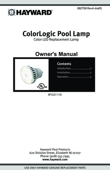
Air Circuit MalfunctionThe mast hand pump is supplied with a pneumatic circuit using a high resistance flexible tubewhich can withstand pressures of 20 [bar] (see red circle in below picture), excluding any failuredue to pneumatic reasons. All connection points are fixed via metal band; it is advisable to performa pre-use check and look for any damage to the system.Parts ReplacementThere are no user serviceable parts, but after prolonged usage, there may be areas that requiresome attention. These are listed as follows. Mast Seal Replacement - Each section of the mast has a seal that may eventually wearoutAir Release Valve Replacement – In the event an air release valve should not functioningit is necessary to replace itFlexible Air Hose ReplacementLocking Device ReplacementPlease contact us for assistance if you suspect any of the areas above, we can arrange either aservice or repair as appropriate.NCAP Lighting system user manual 181113.docx
the lux meter, also for the current illuminance ranges allowable for each test path. An example of a typical EPT and VUT light measurment path is shown below. VUT Path 'S' is typically 25 m, the light points 'X' are divided equally across the test path. EPT Path Light measure points 'Y' are the divided equally between the lamp centre