Transcription
CHROMATOTECGroup / airmotecSTANDARD USER MANUALSMU 0003Application date :9 April 2014Version : N 02Gas-DetectionLauper Instruments AGIrisweg 16BCH-3280 MurtenTel. 41 26 672 30 .chAIRMOVOC C6-C12/AIRMOVOC BTEXWITH INTERNAL PCHistoricVersionN 00Modification natureApplicationdate05 June 201301Creation of a user’s manual of airmoVOCC6C12 with internal and external calibrationModification26 February 201402Addition of airmoVOC BTEX9. April 2014ModifiedchaptersAllJ.3AllEditor : Sandra LANDARTChecked by : Mickael GezatBenoit CalatayudApproved by : Michel ROBERTVisa :Visa :Visa :SMU 0003-02Page 1
STANDARD USER MANUAL n 0003-02CONTENTSA.OBJET. 4B.APPLICATION FIELD . 4C.DEFINITIONS . 4D.REFERENCE DOCUMENTS . 4E.AIRMOVOC C6-C12/AIRMOVOC BTEX PRESENTATION . 5E.1.E.2.E.3.E.4.E.5.INTRODUCTION . 5GENERAL CHARACTERISTICS. 5FUNCTIONAL DIAGRAM . 6FRONT FACE SCHEME . 7PNEUMATIC SCHEME OF AIRMOVOC C6C12/AIRMOVOC BTEX WITH OPTION INTERNALCALIBRATION . 8E.6.PNEUMATIC SCHEME OF AIRMOVOC C6C12/ AIRMOVOC BTEX . 9E.7.SAMPLING PUMP CHARACTERISTICS . 10E.8.BACK FACE. 11F.OPERATING PRINCIPLE OF THE AIRMOVOC C6-C12/AIRMOVOC BTEX . 12F.1.MEASURING PRINCIPLE . 12F.1.1. Introduction . 12F.1.2. Sampling . 12F.1.3. Injection of the sample in the analytical column (trap and desorption) . 12F.1.4. Chromatographic separation . 13F.1.5. Detection and data treatment. 13F.2.SCHEMATIC VISUALISATION OF GAS FLOWS DURING AN ANALYSIS CYCLE . 14F.2.1. Sampling step . 14F.2.2. Analysis step . 16F.3.EXAMPLES OF ANALYSES . 17G.INSTALLING THE AIRMOVOC . 22G.1.RECEIPT OF ANALYSER AND CHECK . 22G.2.ELECTRICAL SUPPLY . 22G.3.GAS SUPPLY AND CONNECTIONS . 23G.3.1. Warning . 23G.3.2. Hydrogen 5.6 . 23G.3.3. Zero air . 23G.3.4. Sample. 24G.4.SIGNAL AND DATA CABLING . 25G.5.MECHANICAL INSTALLATION AND OPERATION POSITION . 25G.6.ENVIRONMENTAL CONDITIONS . 26H.STARTING THE AIRMOVOC C6C12/AIRMOVOC BTEX . 26I.STOP THE AIRMOVOC C6-C12/AIRMOVOC BTEX . 27I.1.CLASSICAL STOP . 27I.2.EMERGENCY STOP . 27I.2.1.Software reset . 28I.2.2.Hardware reset . 28J.ANALYSER CALIBRATION . 29J.1.J.2.J.3.K.BASE SENSITIVITY . 29CALIBRATION STABILITY MONITORING . 30USING AN EXTERNAL STANDARD GAS FOR CALIBRATION IF NO AIRMOCAL DEVICE 33READJUSTMENT OF CALIBRATION (PARAMETER BS) . 34L. PERMEATION TUBE REPLACEMENT (WITH INTERNAL OR EXTERNAL CALIBRATIONDEVICE) . 35M.TROUBLE SHOOTING GUIDE. 36SMU 0003-02Page 2
STANDARD USER MANUAL n 0003-02WARNINGThe described material in this manual contains one or several confidential computer programs thatare the property of AIRMOTEC / CHROMATO-SUD.AIRMOTEC / CHROMATO-SUD authorize the instrument owner to use the program (s) for whatit has been designed to the exclusive of any other use.The total or partial reproduction, the dismantle, the retro-compilation or transcription, or thetransmission of mentioned earlier programs for the use of the owner or a third party are strictlyforbidden.WARRANTYAIRMOTEC / CHROMATO-SUD guarantees these instruments against the manufacturing defaultsduring a twelve month period from the delivery date. The replacement of the defective componentswill be free except the transport or travel fees that will be invoiced according the applicable tariffs.AIRMOTEC / CHROMATO-SUD accepts no liability for damages or possible incurred losses.AIRMOTEC / CHROMATO-SUD provides a spare part service and After Sales Service. Pleasecontact the service engineer responsible for the repair or the spare part repair. The serial number ofthe instrument as well as the description of the trials done and the estimated reasons of thebreakdown should be given to provide you the quickest service.AIRMOTEC / CHROMATO-SUD reserves the right to modify the prices and the characteristics ofthese products.Copyright – 2005, AIRMOTEC / CHROMATO-SUD 15 Rue d’Artiguelongue, 33 240 SAINTANTOINE, FRANCESMU 0003-02Page 3
STANDARD USER MANUAL n 0003-02A. OBJETUser's manual for the analyser airmoVOC C6-C12 or airmoVOC BTEX:- presentation of the analyser- operating principle- installing- starting and stop of the analyser- calibration and troubleshootingB. APPLICATION FIELDAnalysers airmoVOC C6-C12 and airmoVOC BTEX.C. DEFINITIONSD. REFERENCE DOCUMENTSVistachrom user manual 1.47 (reference: SMQ 0004-10 GCSV 147 UK)Vistachrom user manual 1.49 (reference: SMQ 0004-11 GCSV 149 UK)Installation and starting manual of the airmoVOC C6-C12 (reference: SMU Installation andStarting manual of an analyser FID)Easy start airmoVOC C6C12 with option internal calibration (reference: easy start airmoVOC.C6C12 CAL)Easy start airmoVOC C6C12 (reference: easy start airmoVOC.C6-C12 V1 UK)Easy calib airmoVOC C6C12 and airmo BTX Internal and External calibration (reference: EASYCALIB airmoVOC V1)SMU 0003-02Page 4
STANDARD USER MANUAL n 0003-02E. AIRMOVOC C6-C12/AIRMOVOC BTEX PRESENTATIONE.1. INTRODUCTIONThe airmoVOC is a high performance gas chromatograph with Flame ionisation detector (FID) andan on-line sample preparation. It is designed for the analysis of VOC compounds (For example BTEX:Benzene, Toluene, ethyl-benzene, m&p-xylene and o-xylene) in gaseous samples, in ambient (100 ppt) toemission (ppm) concentration ranges. The miniaturisation, the inertia to chemical compounds, the mobilityand flexibility of this analyser have been optimised.Thanks to an integrated CPU board allowing a dialogue with a PC, this analyser is anautomate.The chromatography software allows: A complete automation of the system. The signal acquisition, and data treatment. Data displayed by Peak Viewer software The peak identification thanks to a reference substance table. Data saving on the hard disk. Trend creation allowing a visualisation of the evolution of selected peak retention times andsurface (or concentration of the corresponding compounds).This compact instrument only requires little space, power and gas. The air for FID can begenerated by a compressor (air generator) and hydrogen by a hydrogen generator .Thanks to its highlevel of automation, it is suitable for continuous pollution monitoring. Therefore, the airmoVOC issuitable for in situ operation.E.2. GENERAL CHARACTERISTICSModel: airmoVOC C6-C12 A21022 or airmoVOC BTEX with integrated PC 5UPneumatic valve: 6 ports 1/8 " (A 6UWT), pneumaticReplacement rotor: SSA-6-UWTAnalytical column: Capillary metallic column, id 0.28 mm, length: 30 m, MXT30 CE, 1 µmDetector: Flame ionisation detector (FID)Carrier gas: Hydrogen (quality 5.6)Trap: L 8 cm; id 1.5 mmCritical orifice: 76 µm (Option: 50 µm or 100 µm)Supply voltage: 115 VAC or 230 VAC, 24 volts optionVistachrom softwareDimension: 19", 5UWeight: 25kg (packed: 40kg)Option: -Internal calibrationSMU 0003-02Page 5
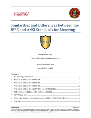
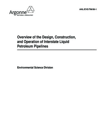
STANDARD USER MANUAL n 0003-02E.3. FUNCTIONAL DIAGRAMSampleInlet4HydrogenInlet1Zero airInlets23InternalStandard gasVENTSamplingPump65AirmoVOC C6-C12With internal PCLegend:1: Hydrogen inlet to connect a Hydroxychrom or a cylinder for carrier gas and flame of FID- 1/16’’fitting2 : Zero air inlet for the FID and the internal permeation oven – 1/8” fitting3 : Zero air inlet for the pneumatic valve commutation-1/8” fitting4: Inlet for Sample (ambient air,.)-1/4" fitting5: Permeation tube VENT. (With option Internal calibration (internal permeation oven))6: Sampling pump- 1/4" fittingSMU 0003-02Page 6
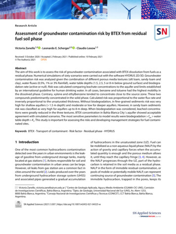
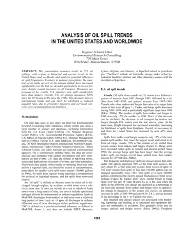
STANDARD USER MANUAL n 0003-02E.4. FRONT FACE SCHEMETouch Pad10,4’’LCD screenInstrumentLed statusSize 5U:Length:Height:Depth:4 USB ports48,0 cm22,0 cm73,0 cmWith the USB Port, you can connect a mouse and a keyboard to an easy using of the internal pc.The front face of the analyser presents: 6 LEDS indicating the state of the Check. 3 concern the chromatograph, and 3 thecommunication with the PC.Cycle:"Running": the green LED is lit during the acquisition."Sampling": the yellow LED is lit during sampling when the sample flow is set by a criticalorifice."Stand by": the red LED is lit when the system is in stand-by.System: A2 communication protocol (when the analyser is connected to Acquisition software andwhen Acquisition software is in the on-line window)"OK": the green LED is lit when the communication between analyser and PC is correct."Warning": the yellow LED is lit to indicate something is wrong. For example, if an acquisition isrunning and if the software is not on the on-line menu (the acquisition is lost) (error number 1xx)."Error": the red LED is lit when an important error has occurred (error number 2xx).SMU 0003-02Page 7
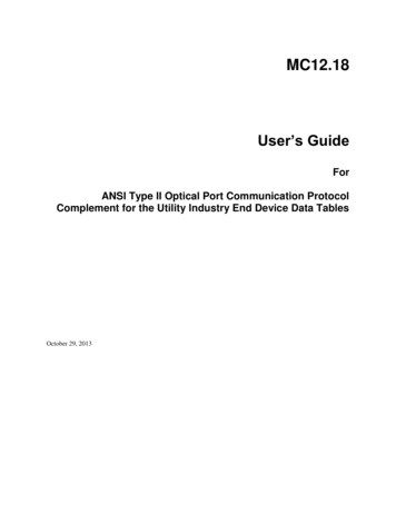
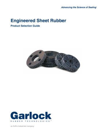
STANDARD USER MANUAL n 0003-02E.5. PNEUMATIC SCHEME OF AIRMOVOC C6C12/AIRMOVOC BTEX WITHOPTION INTERNAL CALIBRATIONInternal permeation ovenfor the calibration of theanalyser with Option:Internal CalibrationSMU 0003-02Page 8
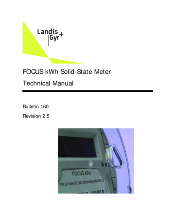
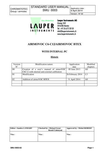
STANDARD USER MANUAL n 0003-02E.6. PNEUMATIC SCHEME OF AIRMOVOC C6C12/ AIRMOVOC BTEXInlet to connect with a solenoid valve of selection:- An external permeation oven which can be inan AirmoCAL- A standard gas cylinder- A sample lineSMU 0003-02Page 9
STANDARD USER MANUAL n 0003-02E.7. SAMPLING PUMP CHARACTERISTICSPressure in hPa (inlet)900dP tubes 20 hPa8006004002000Adsorption tubeInletInletSMU ge 10
STANDARD USER MANUAL n 0003-02E.8. BACK FACERJ45 EthernetPortAnalog outputSub D 9 femaleoptionSize 5U:Length:Height:SMU 0003-02Sample Inlet1/4’’ SwagelokModbus outputSub D 9 maleHydrogen Inlet1/16” SwagelokCalibration Outlet1/8’’ SwagelokZero air Inlets1/8” SwagelokSampling pumpMain Switch1/4 ‘’ Swagelok 115VAC/ 220 VAC42,5 cm21,0 cmPage 11
STANDARD USER MANUAL n 0003-02F. OPERATING PRINCIPLE OF THE AIRMOVOC C6-C12/AIRMOVOCBTEXThe analysis cycle comprise 4 steps described here below.F.1. MEASURING PRINCIPLEF.1.1. INTRODUCTIONA complete cycle of analysis is done in two successive steps.The first stage is the sampling step: it consists to pre-concentrate the VOC contained in theambient air or in the standard gas.The following stage is the analysis step: the trapped VOC are injected in the analyticalcolumn by thermal desorption during few minutes (depending on the cycle duration). Thenthe VOC are separated by the analytical column and detected by the FID.F.1.2. SAMPLINGThe gas sample is drawn by an external pump through a trap, a fine tube containing poroussubstances, which extracts the gas components according to their affinity with these phases. Forexample, permanent gases and water vapour are not retained. The trap phase is chosen so as to trapfrom C6 compounds to C12 compounds.It is possible, if required, to add to the sample flow an exactly known amount of referencestandard compounds.The volume of gas sample (ambient air or gas standard from internal or external calibration)is measured downstream of the adsorption section, thanks to a critical orifice which set the flow andthanks to the sampling time.At the end of the sampling, a relay commutes directing the sample flow to the vent. Thesampling flow is fixed in the instrument by a critical orifice of 50, 76 or 100 µm. The sampling flowis about 10 to 25 ml/min, 35 to 45 ml/min or 60 to 70 ml/min.The entrance pressure of the sample must be near atmospheric pressure so that themeasurement of the volume sampled by the analyser is correct. This measurement is made thanks tothe Pa board and depends on the dimension of the critical orifice. When the analyser is in phase ofsampling step, the Pa board must measure the same pressure whatever the sample entering theanalyser.F.1.3. INJECTION OF THE SAMPLE IN THE ANALYTICAL COLUMN (TRAP ANDDESORPTION)The pneumatic valve that was in "sampling" position gets in "injection" position, therebyinserting the sampling tube in the carrier gas circuit in the way opposite to the sampling way. Atthis time, the trap is heated to desorb the compounds. The gaseous sample is introduced in theanalytical column by the carrier gas flow.SMU 0003-02Page 12
STANDARD USER MANUAL n 0003-02F.1.4. CHROMATOGRAPHIC SEPARATIONThe analytical column is situated in an oven. The temperature is programmed with agradient that starts at 60 seconds of the cycle. The sample components elute in the column at acharacteristic rate (depending of their boiling point and of their interactions with the columnstationary phase). Generally, the retention time of the compounds increases with their molecularweight (boiling point).F.1.5. DETECTION AND DATA TREATMENTAt the extremity of the column, a flame ionisation detector (FID) generates an electricalsignal proportional to the concentration of the sample components as they elute from the column.This electrical signal is digitised to be transferred to the CPU board where the microprocessorprocesses the data (integration, mass or concentration calculation, peak identification.). Allparameters (data results, chromatograms, integration reports.) are then transferred via a RS-232output where they can be displayed and reprocessed by the software. The digitised signal is alsoavailable as an analogue output (0-1V).The data acquisition starts 6s after the trap thermodesorption end.Caution: During this analysis, it is prohibited to exit the ON-LINE menu because the datawould be lost. But, it is possible to reduce the software window.The complete cycle (sampling of the compounds by trapping, injection, chromatographicanalysis, and detection) is repeated. The on-board microprocessor stores the data, calculates theselected compound concentrations and stores them. The compounds identification is made on thebasis of their retention times, and concentrations are calculated in reference to standard compoundanalyses.SMU 0003-02Page 13
STANDARD USER MANUAL n 0003-02F.2. SCHEMATIC VISUALISATION OF GAS FLOWS DURING AN ANALYSISCYCLEF.2.1. SAMPLING STEPAmbient air sampling:Inlet to connectthe sample lineAirmoVOC C6-C12Internal permeation ovenfor the calibration of theanalyser with Option:Internal CalibrationSMU 0003-02Page 14
STANDARD USER MANUAL n 0003-02Standard gas sampling from internal calibration device:AirmoVOC C6-C12Internal permeation ovenfor the calibration of theanalyser with Option:Internal CalibrationStandard gas sampling from an external calibration device:Inlet to connect a standard gaswith a solenoid valve of selection:- An external permeationoven which can be in anAirmoCAL or- A standard gas cylinderSMU 0003-02Page 15
STANDARD USER MANUAL n 0003-02F.2.2. ANALYSIS STEPInlet to connect with a solenoidvalve of selection:- An external permeationoven which can be in anAirmoCAL- A standard gas cylinder- A sample lineAirmoVOC C6-C12Internal permeation ovenfor the calibration of theanalyser with Option:Internal CalibrationSMU 0003-02Page 16
STANDARD USER MANUAL n 0003-02F.3. EXAMPLES OF ANALYSESOperating conditions for airmoVOC C6C12Carrier gas: Hydrogen 430 hPa (so around 3 to 4 ml/min)FID: 170 C - Flame: Air supply: 3 Bar – flow 180 ml/min – Hydrogen supply: 2 Bar - flow 26-27 ml/minThermal desorption: duration 4 minutes with carrier gasSampling flow : - 43.5 ml/min – Cycle duration 1800 seconds- Acquisition duration 1200 secondsElectrometer amplification: High (3) External Standard COV analysisSample: PAMS 58 VOC contained in sampling bag around 2.5 ppb of each compound without dilution.Sampling duration: 600 seconds – Acquisition duration : 1200 secondsSMU 0003-02Page 17
STANDARD USER MANUAL n 0003-02 Standard gas analysis (with Internal or external calibration device)Sampling duration: 600 seconds – Acquisition duration: 1200 seconds - program used: CALIB30MN.mthExternal calibration device: AirmoCAL, dilution system with a permeation oven heated at 40 C and swept bytotal dilution air flow of 243.5 ml/min.Sample: permeation oven containing:N-BUTANE at 14.22 ppb or 34.38 µg/m3 ( /-10 %)BENZENE at 13.98 ppb or 45.42 µg/m3 ( /-10 %)N-HEXANE at 13.80 ppb or 49.46 µg/m3 ( /-10 %)(Molecular volume at 20 C 24.04 l.mol-1)SMU 0003-02Page 18
STANDARD USER MANUAL n 0003-02 Ambient air analysisSampling duration: 1200 seconds – Cycle duration 1800 seconds – Acquisition : 1200 secondsProgram used : AMB30MN.mthSMU 0003-02Page 19
STANDARD USER MANUAL n 0003-02Operating conditions for airmoVOC BTEX:Carrier gas: Hydrogen 378 hPa (so around 3 to 4 ml/min)FID: 150 C - Flame: Air supply: 3 Bar – flow 180 ml/min – Hydrogen supply: 2 Bar - flow 26-27 ml/minThermal desorption: duration 2 minutes with carrier gasSampling flow : - 43.1 ml/min – Cycle duration 900 seconds- Acquisition duration 480 secondsElectrometer amplification: High (3) Standard gas analysis (with Internal or external calibration device)Sampling duration: 660 seconds – Acquisition duration: 480 seconds - program used: CALIB15MN.mthInternal calibration: permeation oven heated at 40 C and swept by total dilution air flow of 243.5 ml/min.SMU 0003-02Page 20
STANDARD USER MANUAL n 0003-02 Ambient air analysisSampling duration: 660 seconds – Cycle duration 900 seconds – Acquisition : 480 secondsProgram used : AMB15MN.mthSMU 0003-02Page 21
STANDARD USER MANUAL n 0003-02G.INSTALLING THE AIRMOVOCG.1. RECEIPT OF ANALYSER AND CHECKEach analyser is inspected and packaged prior to transport with great attention. Immediatelyafter receipt, we recommend to perform a quick visual inspection of the package. If the package isdamaged, report it in writing to the carrier at the time of delivery.The AIRMOVOC is packed in a wood box with protection and maintaining foams placedabove and below the analyser.The AIRMOVOC packaging extraction begins with the opening of the wood box; at thisstage, it is possible to check the visual integrity of the analyser.Any damages must be immediately identified and photographed; it should be reported to thecarrier as well as to your local Distributor or to CHROMATOTEC.For major damages, the AIRMOVOC shall be returned to the manufacturer aftersynchronization with the service department, which can be reached by e-mail at:support@chromatotec.com.In case of non-respect of this procedure, CHROMATOTEC cannot be kept in charge of thecaused damage and cost will be charged to the customer.G.2. ELECTRICAL SUPPLYThis instrument is supplied with 115 VAC or 230 VAC. See the identification plate on the rearface to confirm.The supply must be able to deliver the following power:230 – 50 Hz VAC ( /- 10 %) or 115VAC – 60 Hz ( /- 10 %)Power: 400WFuse: 15AThe use of an inverter is strongly recommended.Power uptake:- Standby: approximately 80 W- Normal operation: approximately 140 W- Short duration peak: approximately 360 W.These values are for guidance only. The actual power uptake varies with the maximum oventemperature, FID temperature and calibration plug-in unit.SMU 0003-02Page 22
STANDARD USER MANUAL n 0003-02G.3. GAS SUPPLY AND CONNECTIONSG.3.1. WARNINGHydrogen is used as carrier gas and as FID combustion gas. Follow safety and securityregulation for this gas. Check all connections for tightness and leaks.The gas supply tubing diameters must be sufficiently large so that the required inlet pressureat the instrument is maintained even under worst-case conditions (such as maximum gas flow rate atmaximum ambient air).All tubing used must be clean, debarred, and free of sward and dust. The use of virgin tubingis recommended. Tubing which has previously been in contact with liquids is not suitable. Thefollowing materials have proven themselves suitable:*Hydrogen 5.6: stainless steel, 1/16″″(in option 1/8”), HPLC grade.*Zero air for FID and permeation tube inlet (with internal calibration): stainless steel, 1/8″″ (inoption ¼”), HPLC grade.*Zero air for air actuator of the pneumatic valve: stainless steel, 1/8″″ (in option ¼”), HPLCgrade.*EVENT of the standard gas: 1/8″″, grade not important.*Sample inlet: glass, 10 mm, or PFA, 1/4″″.*Pump: 1/4″″ grade not important.Before pressurising the tubing for the first time, all connections must be checked forcorrectness of assembly and leak tightness.For a better stability of gas flows, it is recommended to put at the gas cylinders outlet doublepressure release valves. These pressure regulators must be free of plastic (i.e. GC or ultra-highpurity gas quality).All gas supplies are controlled on the airmoVOC C6-C12. The use of unsuitable pressurereducing valves would result in the entry of contaminating hydrocarbons into the measuring system,resulting in incorrect measurement values.Gas and power supply connectors are on the instrument rear panel.The following information refers to the values measured at the inlet connectors to theairmoVOC C6-C12.G.3.2. HYDROGEN 5.6Hydrogen is used as carrier gas and for Hydrogen FID Supply.****Inlet pressure : 2 barConsumption for carrier gas : 3 ml/minConsumption for FID Supply : 27 ml/minConnector: 1/16, stainless steel, swagelok.G.3.3. ZERO AIRAir is used for FID supply and for the pneumatic valve actuator.SMU 0003-02Page 23
STANDARD USER MANUAL n 0003-02* Inlets pressure : 3 bar* Consumption for FID Supply : 180 ml/min* Connectors: 1/8 ″ (in option ¼”), stainless steel, swagelok.With option internal calibration:Air is used also for the permeation oven:* Consumption for permeation oven: 50 ml/min when the relay 7/Valve 5 is not activatedand 250 ml/min when it is activated.The permeation tube needs to be placed in the oven before making the pneumatic connections.G.3.4. SAMPLEa. Sampling systemAn adequate vacuum supply is required to suck up the sample into the instrument and for thesample volume measurement.* Vacuum: 800 hPa (200 hPa maximum at the vacuum outlet).* Pump flow: 1 to 2 l/min.* Connector: 1/4″″, stainless steel, swagelok.The gas sample must be made available at the instrument inlet ("Probe", 1/4" stainless steel,swagelok) under certain defined conditions. It must not contain any liquids. It is recommended thatthe sample be brought to the instrument through enough high dimensioned glass tubing (1/4”PTFE). Metal tubing should be kept as short as possible.b. SampleThe sample gas must not contain liquids or particles.If gas at high temperature and of high relative humidity is being sampled, condensation mayoccur in the instrument. This must be prevented by diluting the sample with dry gas.In option, if there is a particle pollution of the atmosphere, filters can be used. The choice ofthe filter is done according to the level of pollution of ambient environment. If there is a lot of dust,you can use a 2 µm filter. If there is not too much dust, you can use a 5 µm filter.If the ambient air is clean, it is not necessary to use filters to avoid risks of catchingcompounds into filters. The size of particles is not a problem for the column if some reach to gothrough.A filter on the sample must not cause a pressure drop by more than 50 hPa.The filter must be frequently changed, since the slightest accumulation of dust can lead tothe absorption of some compounds in the sample.All methods of sample filtering have some effect on the measurement. It is essential in allcases to check that sample compounds to be analysed actually get through the filter. (This can bedone by making test measurement with standards before and after the filter and comparing theresults).Note: the dust must be removed by using a suitable fine glass wool or glass frit filter in thesample pass.SMU 0003-02Page 24
STANDARD USER MANUAL n 0003-02c. Standard gas (Internal or external calibration device)An external or internal calibration system is used to monitor the stability of the analyser andso to validate the results. This system may consist in an internal or external permeation oven.Calibration is generally done with Benzene permeation tube. To follow the stability onheavy compounds, o-xylene permeation tube can be added.The temperature setting of the permeation oven is: 45 C or 40 C.The permeation tube included:The permanent air dilution flow:32 ng/min at 45 C ( /-10 %) or 15 ng/min at 45 C or40 C ( /-10 %) 50 ml/min (when the relay 7 / valve 5 is off) 250 ml/min (when the relay 7/valve 5 is on)The solenoid valve controlled by the relay 7/valve 5 is activated 120 seconds (in case wherethere is an internal permeation oven) or 300 seconds before the sampling start to be sure thetotal air flow for dilution is stabilized.A VENT on the rear face permits to measure the permeation flow.*Connector: 1/8″″, stainless steel, swagelok.The permeation rate of the calibration tube will be included in the quality control report joinedwith the analyser.G.4. SIGNAL AND DATA CABLINGData cable:RS 232, 9600 Baud. Maximum permissible cable length: 15 meters9 pole plug submin. Type D, male / female.Analogue output:0-1 V, 500 ohms output impedanceTwo 4 mm diameter banana plug sockets (black: -; red : ).Short circuits protection.Switching output:Isolated relay switch controlled by CPU microprocessor.Switching capacity 100 mA at 24 VTwo 4 mm diameter banana plugs.G.5. MECHANICAL INSTALLATION AND OPERATION POSITIONThe usual lack of space in instrumentation cabins, vehicles and measurement stations resultsnecessary in the in
The airmoVOC is a high performance gas chromatograph with Flame ionisation detector (FID) and an on-line sample preparation. It is designed for the analysis of VOC compounds (For example BTEX: Benzene, Toluene, ethyl-benzene, m&p-xylene and o-xylene) in gaseous samples, in ambient (100 ppt) to emission (ppm) concentration ranges.