Transcription
Valco Instruments Co. Inc.Pulsed DischargeDetectorModel D-3-I-8890Instruction Manual8/19North America, South America, and Australia/Oceania contact: Valco Instruments Co. Inc.800 · 367· 8424713 · 688· 9345713 · 688· 8106valco@vici.comsalestechfaxEurope, Asia, and Africa contact: VICI AG InternationalSchenkon, SwitzerlandInt 41 · 41 · 925· 6200Int 41 · 41 · 925· 6201info@vici.chphonefax
This page intentionally left blank for printing purposes
Table of ContentsIntroductionDescription and Operating Principles. 1Safety Notes and Information. 2SymbolsInstallation CategorySafetyComponents of the Detector System. 3System Requirements. 4Components Not Included with the Detector System. 4System Purity. 4Gas Specifications. 5InstallationGeneral Precautions. 6Mounting the Detector. 6Installing and Configuring the FID logic board. 7Gas Connections.10Installing and Purging the Gas Regulator.10Installing and Purging the Helium Purifier.11Connecting the Discharge Gas to the Detector.11Initial Power-Up.12Capillary Column Connection.13Packed Column Connection.13Testing for Leaks.14Mode Selection and SetupHelium Ionization Mode.15Selective Photoionization Mode.15TroubleshootingHigh Background Current.17Low Sensitivity.17No Peaks.17High Noise Level.18Performing a Hydrogen Leak Test.18MaintenanceCleaning or Replacing a Pulsed Discharge Detector Ground Pin.19Removing the Ground Pin.19Cleaning and Inspecting the Ground Pin.21Reinstalling the Ground Pin.21Calibration.21Warranty .22Detector Performance Log.23
This page intentionally left blank for printing purposes
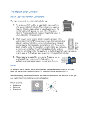
1IntroductionDescription and Operating PrincipleThe D3 is a non-radioactive pulsed discharge ionization detector (PDID),with models available for “plug and play” installation on the Agilent 8890.A schematic representation of the detector is shown in Figure 1.The D3 utilizes a stable, low power, pulsed DC discharge in helium as theionization source. Elutants from the column, flowing counter to the flow ofhelium from the discharge zone, are ionized by photons from the heliumdischarge above. Resulting electrons are focused toward the collectorelectrode by the two bias electrodes.The principal mode of ionization is photoionization by radiation arising from1 the transition of diatomic helium He2(A u ) to the dissociative 2He(1S1)ground state. This is the well-known Hopfield emission. The photon energyfrom the He2 continuum is in the range of 13.5 eV to 17.7 eV.The D3 is essentially non-destructive (0.01 - 0.1% ionization) and highlysensitive. The response to organic compounds is linear over five ordersof magnitude with minimum detectable quantities (MDQs) in the lowpicogram range. The response to fixed gases is positive (the standingcurrent increases), with MDQs in the low ppb range.Detector response is universal except for neon, which has an ionizationpotential of 21.56 eV. Since this potential is close to the energy of theHe* metastable (19.8 eV) but greater than the photon energy from theHe2 continuum, neon exhibits a low ionization efficiency and low detectorresponse.When a dopant is added to the discharge gas, the D3 also functions as aselective photoionization detector. (Suitable dopants include Ar for organiccompounds, Kr for unsaturated compounds, or Xe for polynuclear aromatics.)GROUND PINDISCHARGE REGIONHELIUM INLETHIGH VOLTAGESAPPHIRE INSULATORSCAPILLARY COLUMNCOLLECTOR ELECTRODEVENTCOLUMN INLETFigure 1: Schematic of the D-3 detector
Introduction2Safety Notes and InformationSymbolsATTENTIONRefer to the manual.Installation CategoryThis equipment has been designed for installation category (overvoltagecategory) II, pollution degree 2. It has been approved for use only in heavyindustrial environments and may not be used in the residential, commercial,or light-industrial environment.SafetyThis instrument left the factory in a safe condition. This instruction manualcontains important information and warnings which must be followed by theuser to insure safe operation and to retain the instrument in a safe condition.Use only with an approved mains supply cord having a rating of 2A, 250V,or greater. Do not use this equipment in a manner not specified herein.CAUTION: During normal operation, the detectorproduces ultraviolet energy (UVA, UVB), some ofwhich may be emitted. Do not watch the arc withouteye protection.
Introduction3Components of the Detector SystemComponents of the detector system are listed in Table 1 below. Check thecontents of the packages to verify that everything is present. Contact thefactory if anything is missing or damaged. (NOTE: damaged shipmentsmust remain with the original packaging for freight company inspection.)
Introduction4System RequirementsComponents Not Included with the Detector System Helium (99.999% purity) and other support gases Ultra high purity grade gas pressure regulator with stainless steeldiaphragm Any special adapters required for connection to the gas regulator SS tubing to go from gas supply to GC Flow measuring deviceSystem PurityDischarge/Carrier Gas ConsiderationsThe performance of the detector is adversely affected by the presenceof any impurities in the gas streams (carrier, discharge, or dopant). Werecommend that a quality grade of helium 5.0 (99.999% pure or better)be used at all times. Major gas suppliers offer research grade helium(99.9999% pure) which is particularly low in fixed gas impurities and shouldgive good results in a clean system, but even the highest quality carriergas may contain some water vapor and fixed gas impurities; hence ahelium purifier is included as part of the detector system. The dischargegas should always be run through the helium purifier.Whenever a new batch of discharge gas is received, we recommendperforming a blank GC analysis of the gas in the PDHID mode to detectand identify the presence of any impurities. Gas purity requirementsare specified on the next page.TubingStandards of cleanliness that are suitable for many GC applications maybe totally inadequate for the sensitive PDHID/PDPID work. All surfaces thatcontact the gas stream must be glass or stainless steel. Do not use coppertubing or brass fittings. All tubes must be thoroughly cleaned and bakedbefore use.Flow ControllersThe use of valves or flow controllers in which the gas stream is exposedto any polymer-based packing or lubricating material is to be particularlyavoided.Pressure RegulatorsWe recommend commercial “ultra-pure” grade regulators with stainlesssteel diaphragms. Regulators with diaphragms made of neoprene or otherelastomers should never be used.
Introduction5Gas SpecificationsDetector ModePDHIDAr-PDPIDDischarge gasHelium2% Ar in HeCarrier gasHelium*Kr-PDPIDXe-PDPID1.5% Kr in He 0.8% Xe in He****** Any gas including He which has an ionization potential greater than 12 eV** Any gas including He which has an ionization potential greater than 11 eVPurity Specifications Helium (discharge and carrier gas) must have a minimum purity of99.999%, with 20 ppm Ne impurity. For trace analysis of fixed gases,we strongly recomment 99.9999% purity He with 0.5 ppm Ne. Ar-PDPID mode: Kr-PDPID mode: Xe-PDPID mode:2% 0.2% Ar in 99.999% He balance1.5% 0.1% Kr in 99.999% He balance0.8% 0.2% Xe in 99.999% He balance
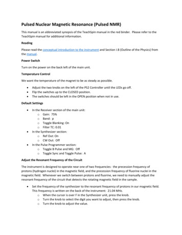
6InstallationCAUTION: A D-3-I-8890 works only on an Agilent 8890GC. It is the only D3 model that will work on an 8890GC; a D-3-I-HP or D-3-I-7890 will not. If you are not surewhich model you have, call the VICI detector departmentwith the detector serial number.General Precautions Do not use plastic/polymer or copper tubes for gas handling andinterconnectons. Use only stainless steel tubing with Valco gold-platedferrules. Do not turn the discharge power on until the helium discharge gas isflowing through the detector. Do not shut off or disconnect the discharge gas when the detector is hot,even if the GC is turned off. Do not turn on the GC during detector installationMounting the Detector1. Place the D3 on the top of the GC in either the front or back detectorposition (Figure 1), and tighten the four captive Torx T-20 screws in thedetector pallet.2. Connect the high voltage cable to the pulser module. The electrometerand heater cables will be connected after the FID logic board is installed.Figure 1: A D3 detector in the “Front” position on an 8890
Installation7 Figure 2: Mounting and connecting the detectorInstalling and Configuring the FID Logic Board1. Refer to the GC manual for instructions on removing access panels.Install the FID logic board as illustrated in Figure 3, at the locationcorresponding to the detector mounting position (front or back).Secure the thumb screw at the top right corner.2. Connect the heater/sensor cable and the electrometer ribbon cable to theFID logic board as TIONFigure 3: FID board
Installation83. Connect the appropriate F-DET (front) or B-DET (back) cable to the logicboard. The AUX DET1 cable is not be used with the VICI D3 detector.4. Turn on GC power and wait for the Opening screen page (Figure 1).5. If the screen in Figure 4 appears, click “Close” on the upper right cornerto close this screen and open the screen in Figure 5. ?Close Hardware that was previously configured is no longer detected at power on. The instrument is not functional as a GC until properly configured. Resolve the issue to enable the hardware to be detected.Remove the hardware from the instrument configuration. Figure 4:Missing Hardware screen Figure 5: Settings screen6. Click “Settings” to open the screen in Figure 6.
Installation97(a) CLICK HERE, THENSELECT A DETECTORLOCATION 7(b) SELECT FRONT OR BACKDETECTOR LOCATION8(c) CHECK THIS BOX USE THIS ARROWTO SCROLL TOTHE NEXT PAGE 8(d) UNCHECK THIS BOXFigure 6: Module Configuration screen7. (a) Click on “Detector” in the left navigation bar, then (b) click “FrontDetector” or “Back Detector”, depending on the D3 installation location.8. (c) Check the “Signal Configured” box, and (d) uncheck the “EPC Configured” box.9. Use the down arrow on the right to scroll down to the screen in Figure 7. Figure 7: Module Configuration continued10. On this screen, (a) check “Configured”, then (b) check “Heater 1 Configured”.11. Click “Apply”.12. Power the GC off and back on to save these changes.
Installation10Gas ConnectionsRemember these three points discussed earlier: (1) all surfaces that contactthe gas stream must be glass or stainless steel; (2) do not use copper tubingor brass fittings; and (3) all tubes must be thoroughly cleaned and bakedbefore use. The installation instructions below assume that the detectordischarge gas will be supplied from a nearby cylinder of heliumof the proper purity. If your installation is different, you may need to modifythe instructions appropriately. A number of Valco fittings have been suppliedin the fittings kit to handle different situations. Since the distance from thehelium supply to the GC varies from installation to installation, we do notsupply tubing to go from that point to the GC.Figure 8 illustrates gas connections for the PD-D3-I detector system. Sincethe distance from the helium supply to the GC varies from installation toinstallation, we do not supply tubing for that purpose.Installing and Purging the Gas TOR(30 mL/min minimum)DISCHARGE GAS(99.999% He)DISCHARGE ATICCONTROLVICIMINIATUREHELIUMPURIFERINJECTORGAS CHROMATOGRAPHFigure 8: Gas connections for a PD-D3-I system1. Make sure the on/off valve on the helium cylinder is completely closed.Screw the CGA fitting nut of the regulator into the helium cylinder. Gobeyond finger-tight, but do not tighten the nut all the way – some leakageis required for the purging operation.2. Turn the output pressure regulating knob completely counterclockwise.3. Open the cylinder on/off valve slightly and quickly close it again.4. Adjust the tightness of the regulator connecting nut to allow a pressurereduction of 690 kPa/sec (100 psi/sec). With a new bottle, the gaugeshould start out at about 14 MPa (2000 psi).5. When the pressure drops into the 1.4 - 3.4 MPa (200 - 500 psi) range,open the cylinder on/off valve slightly and quickly close it again.6. Repeat Step 5 eight or ten times to be certain that all the air is purged.On the final purge, tighten the regulator connecting nut very securely asthe pressure approaches the 2.1 - 3.4 MPa (300 - 500 psi) range.
Installation117. Open the cylinder valve to pressurize the regulator once again. Closethe valve and observe the needle of the high pressure gauge for 15 minutes.If it doesn’t move, there is no critical leak on the high pressure side of theregulator.CAUTION: Never use leak detecting fluids on any part ofthis system.Installing and Purging the Helium Purifier1. If the pressure regulator has a 1/8" male cone-type outlet port, installthe Valco 1/8" external to 1/16" internal reducer (EZR21); if it has a1/4" male cone-type outlet port, install the Valco 1/4" external to 1/16"internal reducer (EZR41). For other regulator outlet fittings, a widevariety of Valco adapters is available.2. Remove the cap from the inlet tube of the Valco helium purifier and insertthe tube fitting into the 1/16" reducer port. (Keep the outlet tube capped.)Use a 1/4" wrench to turn the nut one-quarter turn past the point wherethe ferrule first starts to grab the tubing. Do not remove the fitting. Whenmade up properly, it should be leak-tight.3. Turn the output pressure regulating knob clockwise until the gaugeregisters 345 KPA (50 psi).4. Allow five minutes for equilibration, then turn the regulating knob all theway counterclockwise.5. Observe the needle of the output pressure gauge for 15 minutes. Therewill be a slight initial drop, but if it doesn’t move after that, consider thatall the connections are tight.6. If necessary, use an electronic leak detector to locate any leaks. If aleak detector is not available, tighten all the fittings (including the outputpressure guage), and repressurize the system for another test.CAUTION: Never use leak detecting fluids on anypart of this system.7. Upcap the outlet tube of the purifier and purge the system for15 to 30 minutes at 60 - 80 mL/min to eliminate air from the purifiergetter material.Connecting the Discharge Gas to the Detector1. Connect the discharge gas source to restrictor TGA-R-30F60P, andconnect the restrictor to the detector inlet.2. Connect a flow measuring device to the vent and adjust the heliumpressure to obtain a flow of 30 mL/min.
Installation12Initial Power-UpCAUTION: Always make sure that discharge gas isflowing before heating and powering up the detector.1. Before installing the column, set the gas flow to 30 ml/min (measured atthe detector vent). Let it flow for 15 minutes so that all air is purged fromthe helium purifiers.2. Plug in the helium purifiers and turn on the GC.3. Set the detector temperature to 100 C and allow time for the detectorand helium purifiers to reach the set temperature.4. Plug the 24 VDC output from the power supply (I-23569-1) into the pulsermodule (PD-M2).5. Plug the power supply cord to a 100 - 250 VAC source, and look throughthe hole in the detector housing to see if the discharge is on.CAUTION: During normal operation, the detector produces ultraviolet energy (UVA, UVB), some of which maybe emitted. Do not watch the arc without eye protection.6. Check the standing/background current, and record it in the DetectorPerformance Log on the last page of this manual. Optimum range is600 - 2000 pA at 100 C. Lower current indicates a clean, leak-free system.7. The recommended detector temperature is 20 C above the columntemperature, with a minimum of 100 C. Set the detector to the operatingtemperature required for the intended analysis. When the detector hasreached the set temperature, read and record the standing current.8. Install the column as illustrated on page 12, leaving the oven at ambienttemperature. Start carrier flow, then read and record the standing current.The difference between this reading and the one previous is the ionization ofthe combined impurities in and eluting with the carrier gas. The smallerthe difference, the better the quality of the gas exiting the column.9. Set the column oven to the temperature required for the intendedanalysis. When the oven reaches the set temperature, read and recordthe standing current.The difference with the previous reading is the ionization of the columnbleed. The smaller the difference, the better the column is conditioned.NOTE: Some stationary phases will have a higher bleed than others, butare still suitable for this detector. However, the lower the bleed, the lowerthe chances of contaminating the detector cell.From this point, the standing current should be observed and logged afterany system change. In addition, logging the standing current (with andwithout the column) on a regular basis is an effective monitor of systemintegrity (leaktightness and cleanliness). We also recommend tracking theinternal standard (quantity on column/area count) for sensitivity continuity.
Installation13Capillary Column ConnectionIf the capillary column adapter is installed in the column inlet:1. Make a mark on the column 10.3 cm from the 3 cmCOLUMNFERRULENUTCAPILLARYCOLUMN2. Remove the knurled nut and plug from the capillary column adapter inthe column inlet at the bottom of the detector. (Figure 2) Slide the nutover the end of the column, followed by the appropriate column ferrule(FS.4 or FS.5, or ZF.5V for megabore).3. Seat the ferrule in the detail of the column adapter and begin sliding thecolumn through the capillary column adapter and into the column inlet.4. Get the nut started on the threads and tighten it until you feel it contactthe ferrule, then back off half a turn. Slide the column into the columninlet until the mark is flush with the surface of the knurled nut, and securethe column in the adapter by tightening the knurled nut finger tight only.If the capillary column adapter has been removed, reinstall it:1. Unscrew the liner as far as it will go, then screw the fitting body into thecolumn inlet fingertight.2. While using a 1/8" wrench to prevent rotation of the liner (the part withthe seat for the column ferrule), use a 1/4" wrench to tighten the body ofthe adapter until the ferrule has sealed. The liner will deform if it rotates.3. Proceed to Step 1 above.Packed Column ConnectionCOLUMNINLET8.7 cmPACKEDCOLUMNADAPTER(I-23642-D3)To prevent detector contamination, we stronglyrecommend disconnecting the column from thedetector during column bakeout procedures.The D3 is optimized for packed columns. The column tubing must bethoroughly cleaned and baked before the column is packed. Even whenthe best care is taken in column tubing cleaning and in the support andstationary phase selection, a new column will often bleed compounds,resulting in a considerable increase in the detector baseline. This initialbleed will usually be reduced to acceptable levels after the column isconditioned with clean carrier gas flow for several hours at therecommended bakeout temperature.1. Loosen and remove the knurled nut and plug of the capillary columnadapter, (or remove the column ferrule and the column if one has beeninstalled).PACKEDCOLUMN2. Use a 1/8" wrench to hold the liner – that part of the adapter in which thecolumn ferrule sits. While the 1/8" wrench keeps the liner from rotating,use a 1/4" wrench on the fitting body to loosen the adapter 1/2 turn.
Installation143. Set aside the 1/8" wrench and completely remove the adapter from thecolumn inlet.4. Screw the packed column adapter into the column inlet by hand. Exercisecaution, as the tip of the adapter is very fragile. Then tighten the adapterwith a 1/4" wrench, using an additional wrench on the flats of the columninlet to support the detector.5. Connect the 1/8" column to the packed column adapter with the EZRU21reducing union supplied in the fittings kit.Testing for LeaksIt is critical for the system to be leak-tight, and an additional check at thispoint can save many headaches later on. To test for leaks:1. Cap the tube and pressurize the entire system with helium to 138 kPa(20 psi).2. If the system does not hold pressure, check all the fittings with anelectronic helium leak detector. DO NOT use leak detecting liquids.3. Tighten fittings as required.
Mode Selection and SetupHelium Ionization ModeSince the PDHID mode provides a better indication of the cleanliness andthe integrity (leak tightness) of the system, that mode is utilized for initialtesting and startup. If the system is operating according to the parametersdescribed thus far, it is ready for operation in the PDHID mode.Selective Photoionization ModeTo maximize detector lifetime, turn off the dischargepower when the GC is not actually analyzing samples.This is especially important in the Ar/Kr PID mode.Since the pulsed discharge detector is essentially a windowless heliumphotoionization detector, changing the discharge gas from pure heliumto helium doped with argon, krypton, or xenon changes the dischargeemission profile. This results in a change in the photon energy due toadditional resonance atomic emissions and diatomic emissions from therare gas added. Thus a single detector can be operated in any of thethree photoionization detector (PID) modes: Ar-, Kr-, or Xe-PID.Doped helium is used rather than other pure gases in order to retain thebenefits of the helium: namely, its transparency for Ar, Kr, an Xe resonanceradiation and its efficient cooling of the electrodes. Any problems associatedwith the presence of a window between the photon source and the ionizationchamber are eliminated. In most applications involving current commercialPIDs, analyte condensation and decomposition on the window attenuate thelamp energy, necessitating frequent cleaning and recalibration.Custom gas blends for the pulsed discharge detector are available fromleading gas suppliers at special prices. Alternatively, they may be formulated on the spot by using appropriate fixed restrictors to mix appropriateamounts of pure helium and pure dopant through a tee. Since all gasstreams must pass through a Valco purifier, the second option requires anadditional purifier for each dopant. This may still be more cost effective thanrequesting a custom blend of the more expensive Kr or Xe; since the typicalflow rate required for the pure dopant rare gas is about 0.3 - 1 mL/min,a small lecture bottle can last for a long time. In either case, the totaldischarge gas flow rate should be the same as specified in “Connectingthe Discharge Gas to the Detector” on page 11.15
Mode Selection and Setup16Ar-PDPIDChanging the discharge gas from helium to a mixture of 2% argon inhelium changes the photon energy level from the 17 - 13.5 eV range to the11.8 - 9.8 eV range. The argon emission consists of resonance radiationat 11.8 eV and 11.6 eV and the diatomic Ar2 emission in the range of9.2 - 10.3 eV. Except for fixed gases and a few organic compounds likeCH4 (IP 12.5 eV), CH3CN (IP 12.2 eV) and some fluro-chloro hydrocarbons, the majority of organic compounds have ionization potentialslower than 11.8 eV. Thus the Ar-PDPID is nearly universal, like the flameionization detector, but without the risks associated with the presence ofan open flame and hydrogen.Kr-PDPIDThe recommended proportion is 1.4% Kr in He as the discharge gas.The krypton emission consists principally of resonance lines at 10.6 eVand 10.1 eV. The Kr-PDPID can detect compounds with IP 10.6 eV,which includes unsaturated and cyclic hydrocarbons, alcohols, aldehydes,organic acids, esters, etc.Xe-PDPIDThe recommended proportion is 0.8% Xe in He as the discharge gas. Thexenon emission consists principally of resonance lines at 9.6 eV and 8.4 eV,and can detect compounds with IP 9.6, like aromatics, ethers, alcohols,aldehydes, etc.In addition to the specific compounds named in the three paragraphsabove, certain important inorganic compounds like ammonia, hydrogenperoxide, arsenic trichloride, hydrogen sulfide, arsine, phosphine, nitricoxide, carbon disulfide etc. can be selectively detected using theappropriate photoionization mode.Each dopant gas requires an additional helium purifier, which must bepurged and conditioned in the same manner as the purifier installed onthe discharge gas supply. If you are using more than one dopant, werecommend use of a Valco multiposition stream selection valve so that nofittings have to be disconnected. Not only is this convenient, it keeps thesystem closed, minimizing chances of contamination. When changing fromone dopant to another, allow at least one hour for the old gas to be purgedfrom the system.
17TroubleshootingHigh Background CurrentThe detector isn’t leaking.Check for column bleedand/or leaks in the GC setup.Baseline current falls tonormal range ( 2000 pA)Disconnect the columnand
1. Place the D3 on the top of the GC in either the front or back detector position (Figure 1), and tighten the four captive Torx T-20 screws in the detector pallet. 2. Connect the high voltage cable to the pulser module. The electrometer and heater cables will be connected after the FID logic board is installed.