Transcription
Pulsed Nuclear Magnetic Resonance (Pulsed NMR)This manual is an abbreviated synopsis of the TeachSpin manual in the red binder. Please refer to theTeachSpin manual for additional information.ReadingPlease read the conceptual introduction to the instrument and Section I.B (Outline of the Physics) fromthe manual.Power SwitchTurn on the power on the back left of the main unit.Temperature ControlWe want the temperature of the magnet to be as steady as possible. Adjust the two knobs on the left of the PS2 Controller until the LEDs go off.Flip the switches up to the CLOSED position.The switches should be left in the OPEN position when not in use.Default Settings In the Receiver section of the main unit:o Gain: 75%o Band: po Toggle Blanking: Ono Filter TC: 0.01In the Synthesizer section:o Ref Out: Ono CW Out: OffIn the Pulse Programmer section:o Toggle B Pulse and MG: Offo Toggle Sync and Toggle Pulse: AAdjust the Resonant Frequency of the CircuitThe instrument is designed to operate near one of two frequencies: the precession frequency ofprotons (hydrogen nuclei) in the magnetic field, and the precession frequency of fluorine nuclei in themagnetic field. Whenever we switch between protons and fluorine, we need to manually adjust theresonant frequency of the circuit that detects the rotating magnetic field in the sample. Set the frequency of the synthesizer to the resonant frequency of protons in our magnetic field.This frequency is written on the back of the instrument: 21.04 MHz.o When the cursor is over F in the Synthesizer unit, press the knob.o Turn the knob to select the digit you want to adjust, then press the knob.o Turn the knob to adjust the value.
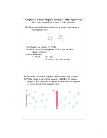
o Press the knob to restore the flashing cursor, then turn the knob to select the upwardarrow.o Press the knob to return to the main menu.In the Pulse Programmer unit, set A len to at least 2.5 s, and set P to 100 ms.Disconnect the cable from Channel 1 of the oscilloscope. Connect the “pickup probe” toChannel 1. Place the probe in the holder in the magnetic field.Set the Channel 1 scale to 5 V. Set the horizontal scale to 2.5 s. Press “Set to Zero” in theHorizontal section of the oscilloscope.We want to adjust the signal to the maximum. There are two screws you can adjust (to changethe capacitances of tuning capacitors). Looking down, the leftmost screw is coarse adjust, andthe third (NOT the second) screw is fine adjust. Do not touch any screws except the first andthird screws!Once you’ve maximized the signal (it should exceed 30 V peak to peak), remove the pickupprobe and reconnect the blue cable to Channel 1.SamplesThe samples in the black box are as follows (if nobody mixed them up): 1A:1B:1C:1D:1E:2A:2B:2C:light mineral oilheavy mineral oilFC-70 (a compound containing fluorine)two discs of “ultra strong” siliconethree discs of “ultra strong” siliconeone disc of FDA siliconetwo discs of FDA siliconethree disc of FDA siliconeYou’re free, of course, to prepare additional samples. In any case, the rubber O-Ring on the vial shouldbe 39 mm above the center of the fluid. (This will place the fluid in the center of the magnetic field.)Adjust Synthesizer FrequencyThe resonant frequency will be slightly differentfrom what’s shown on the label. Place a sample of mineral oil in thesample holder.Set the period to 1 s. Adjust thehorizontal scale on the oscilloscope.Adjust the Synthesizer frequency tominimize the oscillations in Channel 2.Make Channel 2 look as much likeChannel 1 as possible. (Channel 1 is the“envelope” obtained by drawing asmooth line through the maxima ofChannel 2.)
Saving DataSave the images and data that you want on the flash drive.Optimize Magnetic Field UniformityWe want the magnetic field to be as uniform as possible. As the uniformity increases, the signal onChannel 1 lasts longer; the decay time increases. Adjust X, Y, Z, and Z2 coils to maximize the decay time.The 90 PulseThe voltages we’re plotting are proportional to magnetization in the x-y plane. Since equilibriummagnetization is in the z direction (parallel with the magnetic field), the spins need to be rotated 90 from equilibrium to maximize magnetization in the x-y plane. Increase A len from 0 to maximize thesignal, which shows “free induction decay.”Three Reasons the Amplitude Decays after a 90 Pulse The lowest energy state is equilibrium, in which the spins are aligned with the magnetic field.The hydrogen nuclei (protons) gradually release energy to neighboring atoms (“the lattice”) toreturn to equilibrium. This process is called spin-lattice relaxation, and the time constant iscalled T1.The magnetization in the x-y plane is significant only when all the spins are pointing in the samedirection as they precess around the magnetic field. (This means all the spins are in phase.) Thespins gradually “dephase” because the precession frequency is not the same for all hydrogennuclei: the precession frequency depends on the neighboring atoms because these atoms affectthe local magnetic field. This dephasing process is called spin-spin relaxation, and the timeconstant is T2.The external magnetic field is nonuniform, causing the spins to dephase over time. The timeconstant of this process is called T2*.So we need to come up with measurements that isolate the effects of T1 and T2 so that we cancharacterize our sample.The 180 PulseThe 180 pulse should be approximately double the 90 pulse. It should flip the spins 180 fromequilibrium, so there should be no magnetization in the x-y plane. Since x-y magnetization is what’sshown on Channel 1, we want to minimize the signal after 180 pulse. Adjust A len to minimize the signal.Adjust the tuning capacitor to further minimize the signal.Iterate.Measuring T1To determine T1, we first use a 180 pulse to flip the magnetization from the z direction to the –zdirection. Then we want to see how Mz, the magnetization in the z direction, depends on time. Mzreturns to equilibrium according to
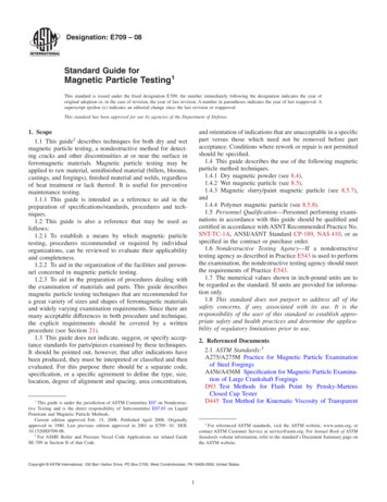
𝑑𝑀𝑧 (𝑡)𝑑𝑡 𝑀0 𝑀𝑧 (𝑡),𝑇1(1)where M0 is the equilibrium magnetization.We want to determine Mz(t), but our system can measure magnetization only in the x-y plane. So, todetermine Mz at a time t after the 180 pulse, we apply a 90 pulse at time t to rotate Mz into the x-yplane. The initial amplitude of the signal is Mz(0). Make a crude estimate of T1 by applying a 90 pulse with decreasing repetition time P until thesignal begins to decrease (because the spins don’t have time to return to equilibrium before thenext pulse).Set A len for a 180 pulse and B len for a 90 pulse. Flip up the B Pulse toggle, and increase thenumber N of B pulses to 1.Adjust the period P to be much larger than your estimate of T1 (to ensure that the systemreturns to equilibrium before the next pair of pulses).Adjust the time between pulses until the signal shrinks to 0. Determine T1 by solving Eq. (1).(What is the initial condition, Mz(0)?)For a more accurate determination of T1, measure Mz(t ) for a variety of and fit the data withthe solution to Eq. (1). The figure below shows the Channel 2 signals (since Channel 1 is alwayspositive) for a variety of . The “envelope” of these signals is the solution to Eq. (1).Spin EchoA 90 pulse tips the spins into the x-y plane. These spins initially point all in the same direction, but theyprecess around the z axis (the magnetic field direction) at different speeds due to inhomogeneity in themagnetic field caused by neighboring atoms. Faster spins precess ahead of the slower spins until somehave the opposite direction as others, and the total magnetization decays to 0.Next, use a 180 pulse to reverse all the spins. Now the slower spins are ahead of the faster spins, so theprecession causes the faster spins to catch up to the slower spins, producing a “spin echo.” The spinecho is weaker than the original amplitude (after the 90 pulse) due to interactions between the spins.The decay of the echo amplitude allows us to determine T2.
Apply a 90 pulse followed by a 180 pulse after some time . You should see the echo at 2 . (Time coincides with the spike halfway between the original signal and the echo.)Measuring T2We can see how the echo amplitude decays over time by applying the following sequence of pulses:90 pulse, delay of , 180 pulse, delay of 2 , 180 pulse, delay of 2 , 180 pulse, delay of 2 , To reduce the accumulated error in repeated 180 pulses (that are really 180 some error), we can usethe Meiboom-Gill (MG) phase shift of 90 between the 90 pulse and the 180 pulses. This means (in arotating reference frame) that the 90 pulse rotates the spins around the y axis, but the 180 pulsesrotate the spins around the x axis. Why does this reduce accumulated error? A detailed and lucidexplanation is in the original paper by Meiboom and Gill.Increase Num B and determine T2 as the exponential decay constant of the echo amplitudes. Makesure the period is large enough.
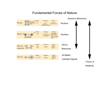
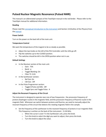
Probing Molecular StructureThe Larmor frequency of nuclei depends on neighboring atoms. Consider a molecule of FC-70 (figurefrom /f9880?lang en®ion US):Different fluorine atoms in this molecule may have different Larmor frequencies depending on wherethey are in the molecule. Chemists use the spectra of detected frequencies to identify the chemicalcomposition of samples. How can we detect multiple frequencies?We need to recognize that the oscillations on Channel 2 (within the exponential envelope) are given bycos[( ref - spins)t], where ref is the synthesizer frequency (which we’ve been setting close to spins byminimizing the oscillations in Channel 2). If we do a Fourier transform of Channel 2, we get a peak at( ref - spins). If there are multiple frequencies spins,1, spins,2, etc., then the Fourier transform showsmultiple peaks at ( ref - spins,1), ( ref - spins,2), etc. To see these peaks in a Fourier transform, they can’tbe too close to 0, so the synthesizer frequency must be slightly off resonance (there should be somewiggles in Channel 2).To measure fluorine spins, we need to change synthesizer frequency and the resonant frequency of thecircuit. Flip the switch from p to F on the Receiver unit.Estimate the resonant frequency of F using fluorine/ hydrogen 0.9408.
Set the synthesizer to this frequency.Place the pickup probe in the sample holder and adjust the tuning capacitors to maximize thesignal during the pulse.Place a sample of FC-70 (from 3A in the box) in the sample holder.Apply a 90 pulse and observe free induction decay.Generate a fast Fourier transform (FFT) of the signal by pressing the MATH button on theoscilloscope.Other ExperimentsAs time allows, perform other experiments described in the manual or based on your own creativity andimagination. The pulsed NMR spectrometer is a very versatile instrument.A Math Problem To Include in Your Lab ReportSolve Eq. (1.16) from the manual to prove that the magnetic moment precesses.
oscilloscope. Other Experiments As time allows, perform other experiments described in the manual or based on your own creativity and imagination. The pulsed NMR spectrometer is a very versatile instrument. A Math Problem To Include in Your Lab Report Solve Eq. (1.16) fro