Transcription
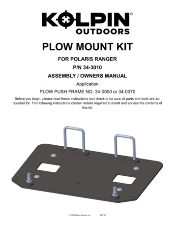
PLOW MOUNT KITFOR POLARIS RANGERP/N 34-3010ASSEMBLY / OWNERS MANUALApplicationPLOW PUSH FRAME NO. 34-0000 or 34-0070Before you begin, please read these instructions and check to be sure all parts and tools are accounted for. The following instructions contain details required to install and service the contents ofthis kit. 2020 Kolpin Outdoors Inc.REV 03
OPERATING INSTRUCTIONSCongratulations! You’ve just purchased the most durable plow component in the industry. Kolpin plow components work great forsummer or winter plowing. With proper care and maintenance, your Kolpin plow system will last for years to come!NOTICEPlow operation requiresadditional components for operation: Kolpin PlowPush Frame, High Rise Plow Push Frame, Winch Kit **These components may be specific to your vehicle.Please read and understand all assembly instructions, notices and warnings before assembling and operating your Kolpin plowsystem.Follow these guidelines to ensure satisfactory operation: Read this manual and your ATV/ UTV operators manual before use. To increase traction during plow operation, operators can try: Securing weight to the ATV/ UTV for additional tire downforce,reducing tire air pressure, or installing tire chains.Periodically check for wear and tightness of all fasteners. Replace or re-torque fasteners as necessary.Before first use, set plow in the furthest right or left angled position to check for interference with the vehicle.Operate with extreme caution on slopes and rough terrain. Be familiar with the area before you plow.Be aware of immovable objects that could be hidden in the area you are plowing.To avoid damage when pushing snow into a pile, reverse direction before raising the plow blade.Do not ram the plow blade into piles of snow.For best results, set the suspension preload of your ATV/ UTV to the stiffest setting.To reduce steering effort and increase mobility, set the air pressure of your tires to the maximum pressure specification.The plow skids are adjustable. General skid setting is even with the plow wear bar bottom edge, higher settings reduce thechance of rocks and gravel from being collected.SAFETY INFORMATIONOur plow systems were designed with your safety in mind. Please read and understand all Cautions, Notices and Warnings in thismanual before you begin. In order to protect you and your ATV/UTV, certain parts of the plow system and/or hardware are designed tofail when the equipment is over-stressed.!DANGER!TO AVOID SERIOUS INJURY OR DEATH:1.DO NOT EXCEED 5 MPH (8 KMH) WITH BLADE INSTALLED.2.OPERATE WITH EXTREME CAUTION ON SLOPES, STEEP GRADES, AND ROUGH TERRAIN.3.ALLOW NO RIDERS ON BLADE OR ATV/UTV WHILE MOVING OR STATIONARY.4.KEEP BYSTANDERS AWAY FROM THE BLADE OR ATV/UTV WHILE MOVING OR STATIONARY.5.WHEN PUSHING HEAVY MATERIAL, DIRECTION CONTROL MAY BECOME DIFFICULT.6.BEFORE ADJUSTING BLADE: STOP ATV/UTV ENGINE; SET AND LOCK BRAKES; RAISE AND LOCK BLADEIN UP POSITION. DO NOT ATTEMPT TO RAISE BLADE BY HAND; USE THE LIFT MECHANISM ONLY.7.LOWER BLADE TO DOWN POSITION WHEN BLADE AND ATV/UTV ARE NOT IN USE.8.READ BLADE'S INSTRUCTION SHEETS AND ATV/UTV OWNER MANUAL. 2020 Kolpin Outdoors Inc.2REV 03
Kit Contents:ItemQty Part DescriptionPart Number11Ranger Mount Plate-22Rear Spacer Bracket-32Spacer-42Square U-Bolts-52Carriage Bolt, Zinc Plated, M10-1.5 x 40mm LG-64Carriage Bolt, Zinc Plated, M8-1.25 x 25mm LG-78Flange Locknut, Zinc Plated, M8-1.25-82Flange Locknut, Zinc Plated, M10-1.5-4628317757 2020 Kolpin Outdoors Inc.3REV 03
BEFORE YOU BEGIN:TOOLS REQUIRED: Your Kolpin accessory is exclusively designed foryour vehicle 10mm Socket Please read and understand all instructions 13mm Socket Verify all parts and tools are accounted for 15mm Socket or Wrench To ensure a satisfactory installation, follow all stepscorrectly and in the sequence described 7/16” Drill Bit Drill Keep these instructions for future reference or forinformational requests To facilitate installation, make sure that your vehicleis clean and free of debris All directions referring to right and left are when therider is sitting on the machine The plastic skid plate will need to be modified to bereinstalled on the vehicleAPPROXIMATE ASSEMBLY TIME: 30 minutesNotes: Removal and modification of the plastic skid plate is recommended. If any hardware is missing, do not return to the store. Call us to help, TollFree 1-877-956-5746.SPARE KITSItemHardware kitP/N 34-0010Description445566778SquareSquare U-BoltsU-BoltsCarriage Bolt, Zinc Plated, M10-1.5 x 40mm LGCarriage Bolt, Zinc Plated, M10-1.5 x 40mm LGCarriage Bolt, Zinc Plated, M8-1.25 x 25mm LGCarriage Bolt, Zinc Plated, M8-1.25 x 25mm LGFlange Locknut, Zinc Plated, M8-1.25FlangeFlange Locknut,Locknut, ZincZinc Plated,Plated, t,Zinc Plated,Hex Nut,Zinc Plated,M8-1.25M10-1.5Hex Nut,Bolt, ZincZinc Plated,Plated, M8-1.25M8-1.25 45mm LGHexHex Bolt, Zinc Plated, M8-1.25 90mm LGHex Bolt, Zinc Plated, M8-1.25 45mm LGSpring Lock Washer, Zinc Plated, M8HexBolt, ZincZincPlated,M8-1.25Flat Washer,Plated,M8 90mm LGSpring Lock Washer, Zinc Plated, M82x2x2x2x2x2x2x2x2x2x-Flat Washer, Zinc Plated, M82xSpare Kit Notes: Spare kits may contain extra hardware that is used for other mount kits. Extra hardware can be discarded. U-bolts supplied in spare kits may be longer than original and may need to be cut to size. 2020 Kolpin Outdoors Inc.4REV 03
Installation Prep (2021 & Up Models Only):Ill. 1-11.For 2012 to 2020 model year vehicles - Proceed toMount Plate Installation Step #1 on Page 6.2.From the underside of the vehicle, using the frontedge of the shock mounting bracket, mark the twohole locations as shown. (See Illustration 1-1).3.These two hole locations will be used for the M10Carriage Bolts [Item 5] and M10 Locknuts [Item 8].Be sure to check for proper 15mm socket or wrenchclearance on the top side in-between the lowershock mounting hardware and chassis prior todrilling. (See Illustration 1-2).FRONT OF VEHICLE4.6” (117MM)10.8” (274MM)Additional View Angle Below:4.Drill the two hole locations using a 7/16” Drill Bit.FRONT OF VEHICLE4.6” (117MM)Note: Touch up paint should be applied to the drilledholes to prevent corrosion.Front Edge of ShockMounting Bracket5.Proceed to Mount Plate Installation Step #1 onPage 6.10.8” (274MM)Ill. 1-2Check for Tool ClearanceKolpin Plow Mount andHardware Shown in Yellow 2020 Kolpin Outdoors Inc.5REV 03
Mount Plate Installation:Ill. 2-11.Use the Mount Plate, item 1, as a pattern to mark therear mounting holes into the plastic skid plate. Aligntwo front mounting holes with the vehicle mountingtabs and then scribe or mark rear hole locations asshown. (See Illustration 2-1 and 2-2).2.Detach the plastic skid plate from the vehicle byremoving the OEM screws as shown and save for reinstall later. Note, some Ranger models have slightlydifferent skid plates than shown. (See Illustration 2-3).3.Item #1Drill holes through the skid plate at locations marked.Use a 7/16” Drill Bit to create an oversized hole thatwill allow some relief when installing hardware. Note:A high speed cutting tool (like a Dremel) with a cuttingbit will also work. (See Illustration 2-4).Ill. 2-2Vehiclemount tabsRear holelocationsIll. 2-3Skid plateScrew & washerHoles drilledIll. 2-4 2020 Kolpin Outdoors Inc.6REV 03
4.Insert the square u-bolts, item 4, around the middleframe tubes as shown. (See Illustration 2-5).Ill. 2-5Middle frame tubesNote: Early 2013 models may require slightmodifications to a thin steel plate section located abovemiddle frame tubes. Drill thru sheet metal to allowsquare u-bolts to fit around middle frame tubes. (SeeIllustration 2-6).Item #4Ill. 2-7Ill. 2-65.Re-install the plastic skid plate onto vehicle andposition square u-bolts thru the drilled out sections asshown. (See Illustration 2-7).6.Place the rear spacer bracket, item #2, onto the squareu-bolts as shown. The spacer will fit in between theplastic skid plate and mount plate. (See illustration2-8).Ill. 2-8Item #2 2020 Kolpin Outdoors Inc.7REV 03
7.Install the Ranger mount plate, item #1, onto thevehicle. The square u-bolts will fit thru holes in rear ofplate as shown. Fasten the u-bolts threads with the M8locknuts, item #7. Do not tighten at this step. Insert theM8 carriage bolts, item #6, and M10 carriage bolts,item #5, thru the plate as shown. (See Illustration 2-9).Item #5Ill. 2-9Item #6Item #1Item #78.Place the spacer, item #3, onto the M10 bolt threadsas shown. The spacer fits in between the vehicle frameand mount plate. (See Illustration 2-10).Item2-3#3Ill.Item #6Ill. 2-109.Fasten the plate to vehicle with M10 locknuts, item #8,as shown. Tighten to specification. (See Illustration2-11).Ill. 2-11Skid PlateItem #810MM FASTENER TORQUE:30 ft. lbs. (41 Nm)SpacerMount Plate 2020 Kolpin Outdoors Inc.8REV 03
10. Tighten the M8 locknuts for the square u-bolts. Do notovertighten. The excess threads can be trimmed, butleave 3-4 threads exposed past the locknut. (See Illustration 2-12).Ill. 2-12Universal mountplate location11. The universal mount plate, not included in kit, will beattached to the Ranger mount plate as shown. The M8carriage bolts will fasten universal plate with M8 locknuts, item #7. Tighten to specification. (See Illustration2-12).Locknut8MM FASTENER TORQUE:17 ft. lbs. (23 Nm) 2020 Kolpin Outdoors Inc.9REV 03
One Year Limited WarrantyFor the period of one (1) year from the purchase date, Kolpin will replace for the original purchaser,free of charge, any part or parts found upon examination by Kolpin to be defective in material,workmanship, or both.All transportation costs incurred submitting product to Kolpin for warranty consideration must beborne by the purchaser. If Kolpin determines that the product must be returned to the factory forcredit, please call 1-877-956-5746 for a Return Merchandise Authorization (RMA) number andshipping instructions.This warranty does not apply to parts that have been damaged by accident, alteration, abuse,improper maintenance, normal wear, or other causes beyond the manufacturer’s control. In order toprotect you and your ATV, certain parts of the plow system and/or hardware are designed to failwhen the equipment is over-stressed. Parts that are lost due to loosening and impropermaintenance are not covered under warranty. This warranty does not cover removal or reinstallationlabor fees of the plow system and related components.Peripheral products such as engines, electric motors, and actuators may carry an originalmanufacturer’s warranty. Most hardware is general in nature and is easily obtained locally. Be sureto replace with minimum metric class 8.8 specification.Kolpin Outdoors, Inc.Telephone: (763)-478-5800Toll Free: (877)-956-5746Fax Number: (800)-245-7569www.kolpin.comEmail: customerservice@kolpin.com 2020 Kolpin Outdoors Inc.10REV 03
Kolpin plow components work great for summer or winter plowing. With proper care and maintenance, your Kolpin plow system will last for years to come! NOTICE Plow operation requires additional components for operation: Kolpin Plow Push Frame, High Rise Plow Push Frame, Winch Kit * *These components may be specific to your vehicle.