Transcription
ICT 775 TransmitterOperation and Installation ManualMade in the USA
Thank you for choosing an Invisible Fence Pet Containment SystemWe believe that you now own the highest quality electronic pet containment system made anywhere. We support this claim by backing InvisibleFence Brand products with a One-Year, Money-BackPerformance Guarantee*, and Warranties whichinclude lightning and surge damage. Refer to yourwarranty card or the back of your sales contract forcomplete details. All of this is backed up by our inter-national network of local Invisible Fence professionals who offer you professional installation, Safe Dog pet training, and prompt service.You are the most important judge of our products and services. When you tell us that we have metor exceeded your expectations for Invisible Fenceproducts, then we are achieving our goal: to continuously keep your pet safe at home .* Good only on pro fe s s i o n a l ly installed systems.Important Safeguards1. Read and Retain Manuals: Read all of theoperating and training instructions before installingand/or using your new Invisible Fence Brand pet containment system.2. Training: Train your pet according to theinstructions in Invisible Fence training manuals.Complete all of the steps before allowing your pet torun free.3. Obey all Cautions and Warnings: Adhere toall of the cautions and warnings contained in this manual and all other manuals pertaining to your InvisibleFence system, and all Invisible Fence system components.4. Service and Repair: Other than repairing thesignal field wire, do not attempt to service anyInvisible Fence equipment yourself. Refer all serviceto an authorized Invisible Fence professional only.5. For Animal Use Only: All Invisible Fence petcontainment systems are designed for animal use only.Never attempt to use this product for any purpose notspecifically described in this manual.2. Never install an Invisible Fence transmitter,LP3000, or any Invisible Fence system componentother than signal field wire outdoors or where theycould be exposed to the outdoor elements, doing sowill void the manufacturer’s warranties.3. Check the transmitter periodically to makesure that it is operating properly and is producing asignal along the signal field wire.4. Caution: Always take the Computer Collar off your pet before making any adjustment to yourInvisible Fence system.5. If you have any questions about any aspect ofyour Invisible Fence system, please call your InvisibleFence professional immediately.Warning: Never install, connect orservice any Invisible Fence systemcomponent or equipment when there isa thunder or lightning storm in the area.Caution: Before starting any work,unplug the transmitter’s 12vACtransformer from the 110v outlet and thetransmitter. Turn off the electric serviceat the circuit breaker panel.IMPORTANT: If, for any reason, your InvisibleFence system does not operate as described in thismanual, or if you encounter any difficulty trainingyour pet, call your Invisible Fence professional immediately.Warning: If you have any reason tobelieve that your pet may pose adanger to others, or that it may harm itselfif it is not kept from crossing the InvisibleBoundary signal wire, you should not relysolely on this product to contain your pet.Warning: The following precautionsshould always be taken.1. Never attempt to install an Invisible Fence petcontainment system unless you have first consultedyour Invisible Fence professional and have InvisibleFence installation instructions.1
Important Safeguards continuedInvisible Fence pet containment will not workunless:1. The 12vAC transformer is plugged into thetransmitter and is plugged into a 110vAC outlet.2. The transmitter is on, connected to the signalfield wire, and producing a signal along the wire.3. The signal field wire is intact, continuous, andthe transmitter’s green LED is blinking on and off.4. The Computer Collar is correctly fitted andworn by your pet.The Computer Collar is adjusted so that thereceiver posts are touching your pet’s skin.5. The Power Cap battery in the receiver is goodand is correctly installed.6. You train your pet as prescribed in InvisibleFence training manuals.Do Not become overly confident that your pethas become conditioned to the Invisible Fence systemsooner than expected. Complete all of the trainingsteps before allowing your pet to run free.About Thunder or Electrical StormsEven though your Invisible Fence system isequipped with lightning surge protection, it is stillpossible that it may be damaged during a thunderstorm, or when an electrical storm is in the areawhere you live. For added peace of mind, you maywant to take the Computer Collar off your petbefore an electrical storm.· Check Your Pet’s Safe AreasAfter a storm has ended, check all of your pet’ssafe areas before you put the Computer Collar backon him. Use the following procedure to make surethat your system is continuing to work properly.Hold the Computer Collar collar so that thereceiver is at about the same height and on thesame angle that it is when your pet is wearing it,and move throughout his safe areas. This shouldinclude all of the safe areas where your pet isallowed to go, in your yard and in your home.If the receiver sounds a warning when it is in asafe area, DO NOT put the Computer Collar backon your pet. Immediately call your local InvisibleFence professional for service.Use a leash or other means to contain your petuntil after the service has been completed.If you have any questions about any aspect ofyour Invisible Fence system, please call your InvisibleFence professional immediately.· At Least Once a Month, and After a ThunderStorm, Check the Width of Your Invisible FenceSystem’s Signal FieldAlways keep a note of the width of yoursystem’s signal field.You only have to check the width of the signalfield from one place on the signal field loop wire.Always check the signal field from the same place.Take the Computer Collar off your pet. Followthe instructions for checking the width of the signalfield on page 9.If the receiver does not sound a warning wherethe edge of the signal is supposed to be, or if it onlysounds a warning when it is closer to the wire thanthe setting of the signal field, immediately call yourInvisible Fence professional for service.Use a leash or other means to contain your petuntil all necessary service has been completed.2
ICT 775 Transmitter InstallationFeatures and FunctionsThe operating frequency of the ICT 775 is factory set to 7K and cannot be changed.An ICT 775 transmitter is designed for two different applications. The first is for a system that willneed a very large signal field wire. The ICT 775 isdesigned for a system with a signal field wire thatwill consist of 2,000 to 5,000 feet(610 to 1525m) ofsignal loop wire, with up to 200 feet(61m) of twistedpair. This transmitter will typically produce a signalfield from a 2,000 foot signal field loop that is a minimum of 5 feet to a maximum of 25 feet(1.5 to 7.6m)wide.The second application that an ICT 775 isdesigned for is to power a 3 sided system, using two,8 foot(2.4m) grounding rods with an opening of up to150 feet(45.74m), connected to up to 2,000 feet(610m) of 12 gauge signal field loop wire, and up to200 feet(61m) of twisted pair. In the three sided mode,the ICT 775 will typically produce a signal field thatcan be adjusted from 5 to 15 feet(1.5 to 4.6m) wide.There is a loop type selector switch on the top,left of the transmitter’s circuit board that must be setto Normal, the UP position, for a system with a standard closed signal field wire, or to 3 Side, the DOWNposition, for 3 sided system operation.There is one signal field wire connector on thebottom, right hand side of the circuit board, and onesignal field adjustment knob to set and adjust thewidth of the signal field.The ICT 775 has a green LED that indicateswhen the power is on, that the signal field wire is connected to the transmitter, and that there is not a breakin the signal field wire. When the system is operatingas it should, in either mode, the LED is alternately ONfor 1 second and OFF for 4 seconds.An ICT 775 has both visual and audible wirebreak indicators. If the signal field wire is broken ordisconnected from the transmitter, the LED will begreen and stay ON without blinking and theBreakAlert will sound an alarm. The wire breakalarm is a rapid, continuous four beeps per second.The LED will stay on and the alarm will sounduntil the break is repaired, or the signal field wire isreconnected to the transmitter, or all power to thetransmitter is turned off by unplugging the trans-3
ICT 775 Transmitter Installation continuedformer from the 110vAC outlet and the transmitter,and if the system has a backup battery, the battery isalso disconnected from the transmitter.The ICT 775 transmitter has an internal batterybackup circuit that will automatically charge an external 12vDC battery. With a charged 12v battery theICT 775 will continue to power the signal field wire ifthere is a 110vAC electric power failure.The ICT 775 has built-in, non-replaceable, loopside lightning surge protection.and index finger of your other hand, gently compressthe top and bottom of the cover plate and remove it.To put the cover back on, align the two tabs on thetop of the cover plate with the two slots, on the top ofthe base, and slide the tabs into the slots. Lock thecover in place by sliding the bottom tab of the coverplate into the bottom slot in the base.The Signal FieldInvisible Fence transmitters produce a coded, lowpower radio signal which travels from the transmitter,along the signal field wire and back to the transmitterto produce a Invisible Barrier wall. This signal is whatactivates your pet’s Computer Collar receiver.There is no hazard in touching or exposing thewire because the wire carries only harmless low voltage electricity.The ICT 775 system functions only when the signal field wire forms one continuous circuit. The signalfield is created where two sides of the wire are separated and is cancelled where two sides are kept closetogether or are twisted together. If there is a break inthe signal field wire, the signal field will be lost andthe system will cease to function.Removing the ICT 775 CoverTo take the cover off the transmitter, hold the baseof the transmitter in one hand and, using the thumbICT 775 system with a backup battery and an Invisible Sentry system monitoring the signal field wire.4
ICT 775 Transmitter Installation continuedPlanning the InstallationInstall the transmitter in a dry indoor location,near a grounded 110vAC electric outlet that offerseasy access to the outside. A garage or basement isusually the best location. If you are not sure whetheryour outlets are grounded or not, contact your electrician. To fasten the transmitter on a wall, use 3/4inch(19mm), #8 or #10 pan-head sheet metal screwsthrough the four round holes in the base of the transmitter case.that it is snug against the ground wire pin. Thentighten the screw an additional 1/4 turn.Caution: Never install a systemor any equipment, or service anyequipment, during a thunder or electricalstorm, or when a thunder stormis near your area.Note: DO NOT tighten the screwmore than a 1/4 turn when tighteningthe grounding wire screw clamp.Over tightening the screw that holds thegrounding wire pin may shear off or fracturethe EARTH ground connector and greatlyreduce the quality of the electrical connection.A sound earth ground connection is essentialand required for lightning protection andthe safety of the system.Grounding the SystemCaution: Before starting any work,you must unplug the 12vACtransformer and turn off the electric serviceat the circuit panel.Caution: Never use a transmitterwhen the EARTH ground connectoron the circuit board is partially shearedor fractured.All outdoor Invisible Fence pet containment systems are equipped with lightning surge protection,which is designed to prevent damage to the transmitter in the event of an electrical surge.If the system is properly installed and grounded,and is equipped with an Invisible Fence lightning protection device, Invisible Fence will repair or replace,at our option, any transmitter, transmitter circuitboard, transformer, or lightning protector damaged byan electrical surge for as long as the original ownerowns the system.Before you connect the signal field wire, orbackup battery, or connect the transformer to thetransmitter, you must ground the system.Grounding Instructions to an Electric OutletRemove the screw that holds the cover on thegrounded 110vAC electric outlet. Put this screwthrough the grounding wire ring terminal. Then putthe screw, with the ring terminal through the outletcover plate and screw it back into the outlet. Thegrounding wire must be on the outside of the outletcover. If the cover plate screw is plastic, replace itwith a size 6-32 x 1/2 inch oval-head metal screw.Connecting the Grounding Wireto the ICT 775 Circuit BoardPut the grounding wire pin into the square screwclamp marked EARTH on the transmitter circuitboard. Be careful not to push the pin too far throughthe connector. The grounding wire pin must nottouch any other component on the circuit board. Usea flat head screwdriver with a 1/8 inch(3.2mm) wideblade to tighten the connector screw only enough so5
ICT 775 Transmitter Installation continuedIMPORTANT: During the grounding process,make sure that the screw and the threads in the outletare clean. All foreign matter such as paint, corrosion,grease, and dirt must be removed. There must be metalto metal contact of the mating threads. Also, the underside of the screw head and ring terminal must be clean.If the surfaces appear corroded, scrape, wire brush, orsand each thoroughly, or replace them.the Invisible Fence system operating if there is anelectric utility power outage. A fully charged 12vDCbattery with a 5.0Ah(Amp hours) rating will powerthe system for approximately 10 hours with the signalfield set to the maximum width. Conversely, the narrower the signal field is set, the longer the battery willcontinue to power the system.Warning: Never connect a backupbattery to a transmitter while 110vACpower is being supplied to the transmitter.Before you connect the battery make surethat the transformer is unplugged fromboth the 110v outlet and the transmitter.Caution: DO NOT make any sharpbends in the grounding wire.Grounding Instructions to a Ground FaultCircuit Interrupter, GFCI ReceptacleDefinition: A GFCI receptacle provides a function similar to a circuit breaker. When it detects aground fault in the circuit’s electric current the GFCItrips and cuts the power. A ground fault is an abnormal electrical condition which is not desirable.A backup battery should always be installed in anInvisible Fence battery box. The box is made of corrosion proof, impact resistant ABS plastic to securelyhold the battery in place. It has integral, internal reinforcing ribs that add structuralstrength and keep the battery level,and is ventilated to prevent heatbuildup.Warning: If an externalbackup battery is leftunprotected or on the flooror the ground, this may lead topremature battery failure.Install the battery box on the wallnear the transmitter. Hold the batterybox on the wall where you want tofasten it and use the round holesthrough the back edges of the box as a template tomark the wall where you will drill the holes for thefasteners.Lace a 16 inch(40.6cm)long zip tie through the twoholes in each side of the insidefront corners of thebattery box. The ziptie should form a Uinside the middle of the box.The outboard ends of thetwo battery wires, the ends thatare connected to the terminalson the battery, each have a spade quick-connect.Connect the spade quick-connect on the REDwire to the positive ( ) terminal on the 12v battery.1. Remove the outlet cover plate.2. Remove the bottom screw holding the GFCIoutlet in the junction box.3. Put the screw through the grounding wire ringterminal.4. Refasten the screw, with the ring terminal onit, to the GFCI junction box and tighten it.5. File a notch in the bottom edge of the coverplate slightly larger than the diameter of the 12 gaugegrounding wire. Bend the wire to fit in the notch andreattach the cover plate keeping the wire in the notch.Installing a Battery BackupAn external 12vDC battery connected to an ICT775 transmitter will supply the power needed to keep6
ICT 775 Transmitter Installation continuedboard between the LED and the 12vAC Power Jack.The battery connector is designed so that the plugthat holds the two inboard ends of the wires that areconnected to the battery will only go into it one way,making it nearly impossible to reverse the battery wire connectionsat the transmitter.Connect the spade quick-connecton the BLACK wire to the negative(-) terminal on the 12v battery.Caution: Be careful not to reversethe RED and BLACK wires whenyou connect them to the terminals on the battery. The RED wire is positive( ) andthe BLACK wire is negative(--).There is a replaceable, 2amp fast-blow fuse onthe bottom left side of the transmitter’s circuit boardto protect the transmitter and the battery. If the wiresare accidentally crossed when they are connected tothe battery, or if the plug is connected to the transmitter incorrectly, the fuse will blow.Slide thebattery into thebattery box.The bottom ofthe batteryshould sit onthe internalreinforcing ribson the bottomof the box.When thebattery is in the battery box,cinch the zip tie tightlyaround the battery to hold thebattery securely in the box.Use 4, 3/4 inch(19mm),#10 pan-head sheet metalscrews to fasten the batterybox to the wall.After the battery box hasbeen fastened to the wall,connect the battery tothe transmitter’scircuit board.Finish the installationby feeding any loose wirebetween the transmitterand the battery box into thehole on the back edge ofthe battery box.ICT 775 transmitters have a two position headerconnector that the plug holding the two leads from thebattery is plugged into. The rectangular connector hastwo metal prongs and is labeled -- BATT . It islocated on the bottom, left of the transmitter’s circuitBatteries Recommended by Invisible Technologies,Inc., are all 12vDC, 5.0Amp hours.Approved BatteriesAll are lead-acid, 12vDC, 5.0Ah.Power Mate , PM1255;Power Sonic , PS-1252;Panasonic , LCR12V5P;Cell-Con, PN 90195Warning: Only use one of theapproved lead-acid batteries.Using a battery that is not lead-acid, ora battery with a different voltage can damageboth the transmitter and the battery.Note: The recommended 12vDClead-acid batteries have a five yearshelf life, and should be replaced,whether they have been engaged often or not,after that time.Detecting Low Voltage in the Backup BatteryAfter a 12v battery is fully charged, a microprocessor in the transmitter will automatically checkthe battery’s voltage. If the voltage of the battery7
ICT 775 Transmitter Installation continueddrops between 11vDC and 9vDC, the transmitter’sBreakAlert alarm will sound. The low battery alarmwill continue until 110vAC power is restored and thebattery voltage is recharged to greater than 11vDC.The alarm is a single, one second beep that will soundonce a minute.The LED on the transmitter that is green duringnormal operation, will turn red indicating that there isa 110vAC power failure and that the system is operating on 12vDC battery backup power. The red LEDwill alternately blink ON for one second and OFF forfour seconds.A fully discharged 5.0Ah battery will take fivetimes its projected operating time to completelyrecharge. The battery will take about 50 hours to fullycharge. The transmitter automatically charges thebackup battery while the system is operating normallyon 110vAC power.Use your thumb to push back and down hard onthe white tabs located on top of the signal field wireconnector. While holding down the tabs,put one stripped end of the twisted wireinto each of the openings in the connector. Either end of the wire may be put intoeither opening. Hold the ends of the wirein the openings and release the tabs. Theends of the wire will automatically becrimped into the wire connector.Note: How long it will take the batteryto recharge to 11vDC will depend onhow low the battery’s voltage has dropped andhow wide the signal field is. The lower thevoltage is and the wider the signal field is,the longer it will take to recharge the battery.Note: You will have to apply pressureto push down the white tabs on theconnector; the connector will not break, sodo not be concerned about pushing too hard.To remove the signal field wire from the connector, push back and down on the tabs on the connectorand pull the ends of the wire out.Note: A battery will take five times itsrated operating time to fully charge.A 5.0Ah battery will take about 50 hoursto charge to full power.Note: Before you turn on the power tothe ICT 775 system be sure that theloop type selector switch is in the mode that youwill want it to be. Either the Normal position,UP, for a closed signal field wire, or the 3 Sideposition, DOWN for a three sided system.If the voltage of the battery drops too low to produce a signal field, the LED will not be lit.Connecting the Signal Field WireConnect the twisted pair ends of the signal fieldwire to the ICT 775. Strip about 1/4 inch(6.4mm) ofinsulation off each of the two ends of the twisted wire.Twist the exposed wire strands on each end of thewires together to hold the strands together. You want tomake sure that a loose strand on one end of the wiredoes not touch the other end of the wire, or or the otheropening in the wire connector, or any other componenton the transmitter’s circuit board.Connect each end of the twisted pair to the ICT775 signal field wire connector labeled LOOP.8
ICT 775 Transmitter Installation continuedICT 775, 12vAC Transformer,Model 100-0018-01Only use the model 100-0018-01, 12vAC transformer to supply the power to an ICT 775 system.This transformer will supply the power necessary topower the ICT 775. Specifications:INPUT: 120vAC 60Hz 33.5WOUTPUT: 12vAC 1667mAUL/CSA CLASS 2 TransformerUL listed/CSA certifiedThe width of the signal field is set and checkedin exactly the same manner, whether for a standardsystem with a closed signal field loop, or for a 3 sidedsystem.The signal field adjustment knob is near the topof the ICT 775 circuit board, it is surrounded by thenumbers 1 to 10. Turning the signal field adjustmentknob clockwise increases the width of the signal fieldand counter clockwise decreases the width.These adjustments do notchange the correction level of thereceiver, they only change the widthof the signal field from the signalfield wire loop.Start by turning the signal fieldadjustment knob to 5, the mid range.Once again, wait up to 1 minute for the transmitter to stabilize before you check the width of the signal field with a Computer Collar receiver. TheBreakAlert may initially sound an alarm until thetransmitter stabilizes.After the transmitter has stabil i ze d, check the width of the signal fieldby holding a Computer Collar so that thereceiver is parallel to the loop wire. Hold thecollar so that the receiver is at about thesame height and on the same angle that itwill be when your pet is wearing it andwalk slowly toward the signal fieldloop wire. The receiver willsound a warning when itis at the edge ofthe signal field.Warning: The model100-0018-01 is theonly transformer authorizedby Invisible Technologies, Inc.to be used to supply the powerto an ICT 775. The use of anyother transformer may result ina malfunction of the transmitter and the ICT 775 system.When you turn on thepower to an ICT 775 transmitter, it will take the transmitter up to 1 minute to stabilize. While the transmitter is stabilizing the BreakAlert alarm will sound.After the transmitter has stabilized and the alarm hasshut off, proceed to set the width of the signal fieldIf the alarm continues to sound for more than aminute, there is a problem with the signal field wire.Caution: Always be sure to takethe Computer Collar off your petbefore setting the signal field or making anyadjustment to your Invisible Fence System.Note: A Computer Collar receiverhas a fail safe mechanism.The receiver will go through three completecycles of 10 seconds on and 10 seconds offand then shut down. It will not reactivateuntil it is taken completely out of the thesignal field, and is then brought back into it.Setting and Checking the Widthof the ICT 775 Signal FieldA signal field that is broadcasted out from thesignal field wire is what activates your pet's ComputerCollar receiver. The signal field can be set to variousdistances from a signal field wire loop depending onthe layout and size of your property, and the temperament of your dog. The average setting of the signalfield is 6 to 10 feet(1.8 to 3m) wide.Check to be sure that the transmitter is turned onand that the loop type selector switch is set to the typeof system that you have. For a standard closed systemwith a continuous signal field wire, the switch is set toNormal, the UP position. For a 3 sided system, theswitch is set to 3 Side, the DOWN position.Make small gradual adjustments with the signalfield adjustment knob and check the width of the signal field after each adjustment.After checking the width of the signal field, wait1 minute before you change the setting of the signalfield again, and 1 more minute before checking thewidth of the new signal field setting.9
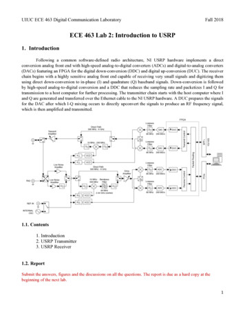
ICT 775 Transmitter Installation continued6. NEVER, under any circ u m s t a n c e s , u s ethis pro d u c t for any purpose other than thats t ated in this m a nual. Inv i s i ble Fe n c e systems aredesigned for animal use only.Computer Collar ReceiversCAUTION AND CAREFeatures and FunctionsComputer Collar receivers are water resistant,microprocessor controlled units powered by a special3v lithium Power Cap battery.An R series Computer Collar can be usedwith allICT700 series, Invisible Gate, and IFA12 transmitters.Computer Collar receivers are available withShort, Long, or Short-Space receiver posts to fit different size dogs and work well with any type of coatComputer Collar receivers can be fitted withshunts to reduce the correction level of there c e iver fo r small pets who are shy or timid.An Invisible Fence Computer Collarwill not work unless:1. You train your pet as pre s c ribed in the“I nv i s i ble Fence SafeDog Training Manual”.2. The Computer Collar is worn snugly on yourpet’s neck under the lower jaw.3. The Computer Collar is adjusted so that thereceiver’s posts are touching your pet’s skin.4. The Power Cap battery in the Computer Collarreceiver is good and is correctly installed, see“Changing the Computer Collar Receiver’s PowerCap Battery” on page 11.5. The transmitter is on, c o n n e c t e d to thesignal field wire, and producing a signal field alongthe entire signal field wire.6 . The signal field wire is intact and making acomplete circuit.The following precautions should also be taken:1. Always take the Computer Collar offyour pet before you make any adjustmentto your Invisible Fence system.2. Gradually allow your pet to become accustomed to its new Computer Collar. Take off thecollar every night during the first month and periodically thereafter. This will ensure proper fit andavoid the possibility of any irritation that the postsmay cause to your pet’s skin.3. Check the Computer Collar near your television set(s). Although the re c e iver has a decoding circ u i t , some televisions may produce acoded signal similar to the Inv i s i ble Fence signaland may cause the re c e iver to activate when it isclose to a telev i s i o n .4. DO NOT s e c u re the corre c t i o nposts in the re c e iver with anykind of glue or adhesive.A LWAY S use the posttightening tool to tightenthe re c e iver posts.5. Check the tra n s m i t t e r p e ri o d i c a l ly tom a ke sure that it is operating pro p e rly and producing a signal fi e l d.Short, Long, andShort-Space Receiver PostsR21 v3 Series ReceiversThe R21 v3 Computer Collar receivers have anadded feature. The v3will beep once when aPower Cap battery isinstalled. The beep indicates that the microprocessor in the receiveris working and that thePower Cap battery hasenoughvoltageto10
Computer Collar Receivers continuedpower the receiver.The three small circular indentations, equidistantly spaced around the outer edge of the base thatsupports the center battery contact in the receiver,indicate that the receiver is an R21 v3 seriesComputer Collar.of times a pet challenges the systemboundary, and the fit of the collar onthe pet’s neck. In cold weather, forexample, it may be necessary toreplace the battery more often. YourInvisible Fence professional should recommend a schedule for regularly changing areceiver’s battery. We recommend that you ask yourDealer about a battery replacement plan.Fitting the Computer CollarTo wo rk pro p e rly, the correction posts on theComputer Collar receiver must touch your pet’sskin. Posts are available in three different sizes toensure a proper fit for every pet: s h o rt , 1/2 inch;long, 3/4 inch; and short-spaced posts. Adjust thecollar so it’s snug enough to slide one fi n ge rbetween a post and your pet’s neck. The receivershould be positioned underneath your pet’s neckwith the posts pointing up and the top of thereceiver pointing fo r wa rd, toward your pet’s nose.Periodic adjustment of the Computer Collar maybe necessary as your pet’s coat, weight and ageNote: Invisible Technologies, Inc.recommends that a customer subscribeto a battery replacement plan where freshPower Cap batteries are mailed directly to themon a regular schedule.Your Invisible Fence professional candetermine the best schedule for you.Warning: The use of any battery other than abattery authorized by Invisible Technologies,Inc. can cause a receiver to operate erratically. Failureof the receiver d
1. Never attempt to install an Invisible Fence pet containment system unless you have first consulted your Invisible Fence professional and have Invisible Fence installation instructions. 2. Never install an Invisible Fence transmitter, LP3000, or any Invisible Fence system component other than signal field wire outdoors or where they