Transcription
Floorplan-aware Bus Architecture Synthesis Sudeep Pasricha†, Nikil Dutt†, Elaheh Bozorgzadeh† and Mohamed Ben-Romdhane‡†Center for Embedded Computer SystemsUniversity of California IrvineIrvine, CA 92697-3425, USA1 (949) 824-2248{sudeep, dutt, eli}@cecs.uci.edu‡Conexant Systems Inc.4000 Mac Arthur BlvdNewport Beach, CA 92660 USA1 (949) 483-4600m.benromdhane@conexant.comCECS Technical Report #04-27October, 2004 This work was partially supported by grants from Conexant Systems Inc. and UC Micro (03-029)1
Floorplan-aware Bus Architecture Synthesis Sudeep Pasricha†, Nikil Dutt†, Elaheh Bozorgzadeh† and Mohamed Ben-Romdhane‡†Center for Embedded Computer SystemsUniversity of California IrvineIrvine, CA 92697-3425, USA1 (949) 824-2248{sudeep, dutt, eli}@cecs.uci.edu‡Conexant Systems Inc.4000 Mac Arthur BlvdNewport Beach, CA 92660 USA1 (949) 483-4600m.benromdhane@conexant.comCECS Technical Report #04-27October, 2004AbstractAs System-on-Chip (SoC) designs become more complex, it is becoming harder to design communicationarchitectures to handle the ever increasing volumes of inter-component communication. Manual traversal of thevast communication design space to synthesize a communication architecture that meets performancerequirements becomes infeasible. In this technical report, we address this problem by proposing an automatedapproach for synthesizing cost-effective, bus-based communication architectures that satisfy the performanceconstraints in a design. Our synthesis flow also incorporates a high-level floorplanning and wire delay estimationengine to evaluate the feasibility of the synthesized bus architecture and detect timing violations early in thedesign flow. We present case studies of network communication SoC subsystems for which we synthesized busarchitectures, detected timing violations and generated core placements in a matter of hours instead of severaldays it took for a manual effort. This work was partially supported by grants from Conexant Systems Inc. and UC Micro (03-029)2
1. INTRODUCTIONImprovements in process technology have led to more and more functionality being integrated onto a singlechip, which has in turn resulted in a sharp increase in the amount of overall on-chip communication volumesbetween the integrated components. In such highly integrated systems, on-chip communication is expected tobecome a major performance bottleneck [1]. Already, increasingly demanding performance requirements from thenext generation of multimedia, broadband and network applications are making interconnect design a challengingproposition.Bus-based communication architectures [2-4] remain a popular choice for handling on-chip communication inSoC designs today, because they are simple to design and take up very little area. However, selecting andreconfiguring standard bus-based communication architectures such as AMBA [2] and CoreConnect [3], to meetapplication specific performance requirements, is a very time consuming process. This is due to the largeexploration space created by customizable bus topologies, arbitration protocols, DMA burst sizes, data buswidths, bus clock speeds and buffer sizes, all of which significantly impact system performance [5][12][26].To counter the challenge of ever increasing on-chip bandwidth requirements and a vast communicationexploration space, early planning of the interconnect architecture at the system level must become an integral partof a SoC design process. However the complex interplay between communication architecture parameters is hardto analyze effectively even at the system level. Previous research in this area (discussed in Section 2) has beenlimited to identifying and automating the exploration of small subsets of this design space. Very often, designersend up evaluating the communication design space by creating simulation models annotated with detail based onexperience, and manually iterating through different design configurations. Such an effort remains timeconsuming and produces systems which are generally overdesigned for the application at hand.To address this problem, we propose a bus architecture synthesis approach in this report, which automates thegeneration of a cost effective communication architecture for a SoC. We make use of SystemC [23] to quicklycapture components at the behavioral system-level and automate the bus architecture synthesis for the design. Thenovelty of our approach is in the ability to automatically satisfy performance constraints and detect bus cycle timeviolations, while synthesizing a feasible, low-cost configuration of a standard bus-based communicationarchitecture (such as [2]) which is commonly used in SoC designs. Our approach synthesizes the bus topology, aswell as values for bus architecture parameters such as arbitration priority orderings, data bus widths, bus clockspeeds and DMA burst sizes. Additionally, we make use of a high-level floorplanning engine to generateestimates of core placements on the chip. Typically, once the system architecture is frozen, it takes several monthsbefore a floorplan of the design becomes available. Violations of timing constraints, detected at this late stage, canrequire changes in the architecture which can severely impact time-to-market. Our high-level floorplanning andwire delay estimation engines detect these timing violations early in the design flow at the system level, wherearchitectural modifications and tradeoff analysis can be performed quickly and efficiently to eliminate suchviolations. To demonstrate the usefulness of our approach, we present case studies of network communicationSoC subsystems, used for data packet processing and forwarding. Compared to a manual effort which tookseveral days and produced overdesigned systems, our automated flow was able to synthesize low-cost busarchitectures, detect timing violations and generate core placements which satisfied performance constraints forthe SoC subsystems in a matter of a few hours.2. RELATED WORKThere is already a significant body of research in the area of bus architecture synthesis. Early work was aimedat minimizing bus width [6], interface synthesis and simple synchronization protocol selection [7] and topologygeneration for simple busses without arbitration [8]. Ryu et al. [9] performed studies to find optimal bustopologies for a SoC design. Pinto et al. [10] proposed an algorithm for constraint-driven topology synthesisunder the assumption that relative positions of components were fixed. Lyonnard et al. [11] proposed a synthesisflow which supported shared bus and point to point connection templates. These templates have to beparameterized manually, which makes the process time consuming. Lahiri et al. [12] designed communication3
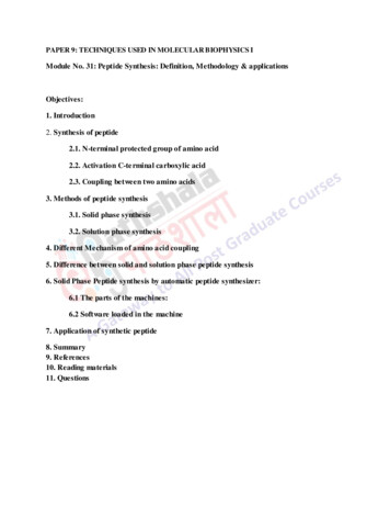
architectures after exploring different solutions using fast performance simulation. However, they assumed thebus topology to be given. Shin et al. [13] used a genetic algorithm for automating the generation of busarchitecture parameters to meet performance requirements. However, they do not focus on bus topology synthesis.Our approach differs from these existing approaches in the way we automate the synthesis of not only the bustopology, but also the generation of values for bus architecture parameters, while also satisfying performanceconstraints.A key component of our synthesis flow is the integrated floorplanner. There have been other approaches inthe past which have made use of a floorplanning tool [14-18] in a synthesis flow, but for different reasons.Bergamaschi et al. [18] and Thepayasuwan et al. [14] used the floorplanner to generate an early core placementestimate. Drinic et al. [15] used the floorplanner to determine feasibility of the synthesized design by comparingestimates of wire length with an upper bound on wire length. However an upper bound on wire length has thedisadvantage of not accounting for varying capacitive loads of the components. Hu et al. [16] also used thefloorplanner to estimate wire length, which they used to calculate energy consumption in point to point networks.Dick et al. [17] invoked the floorplanner repeatedly in their custom bus topology synthesis approach to obtainglobal wiring delays and ensure that real time deadlines were met. Unlike existing approaches, the floorplanner inour approach is used to identify bus cycle time violations and verify the feasibility of the synthesized busarchitecture early in the design flow. We believe that this step will become increasingly important in the deepsubmicron era as clock speeds increase and lengthy propagation delays cause violations of timing constraints thatwill need to be detected and corrected early in the design flow.3. AUTOMATED BUS SYNTHESISThis section describes our approach for automated bus architecture synthesis. Section 3.1 formulates theproblem and presents our assumptions. Section 3.2 discusses the simulation engine while Section 3.3 describescommunication parameter constraints, which guide the bus synthesis process. Section 3.4 gives an overview ofour floorplan and wire delay calculation engines used for detecting timing violations in the design. Finally,Section 3.5 presents our automated bus architecture synthesis approach in detail.3.1 Problem FormulationWe are given a SoC having several components (IPs) that need to communicate with each other. The standardbus-based communication architecture (e.g. AMBA [2], CoreConnect [3]) which determines the pins at the IPinterface and for which the bus topology and communication parameter values must be synthesized, is alsospecified. It is assumed that hardware software partitioning has taken place and that the appropriate functionalityhas been mapped onto hardware and software. The IPs are assumed to be standard “black box” librarycomponents which cannot be modified during the bus synthesis process, except for the memory 2360 MbpsS2S2MEM3MEM3Figure 1. Communication Throughput Graph (CTG)Typically, SoC designs need to satisfy performance constraints which are generally dependent on the natureof the application. The throughput of communication between components is a good measure of the performance4
of a system [8]. We assume that we are given one or more throughput constraints for the system that need to besatisfied. These constraints can involve communication between two or more IPs. Figure 1 shows aCommunication Throughput Graph (CTG) which is a directed graph, where each vertex v represents a componentin the system, and an edge aij connects components i and j that need to communicate with each other. Each vertexv contains information about the component it represents, such as its area, dimensions (fixed width/height oraspect ratio), capacitive loads on output pins and which bus type it can be connected to – a main high bandwidthbus like AHB [2], a peripheral low bandwidth bus like APB [2] or both. An edge aij is associated with athroughput constraint (aij) if it lies within a throughput constraint path (TCP). Figure 1 shows a TCP involvingCPU1, MEM1, S1 and M2 components, where the rate of data packets streaming out of M2 must not fall below360 Mbps. A TCP, in general, has a single master for which data throughput must be maintained and othermasters, slaves and memories which are in the critical path that impacts the maintenance of the throughput.The problem then is to generate a bus topology, and determine bus architecture parameter values for the selectedstandard bus-based communication architecture, while ensuring that all throughput constraints in the system aresatisfied. In addition, we want to consider layout information of the chip to detect bus cycle time violations, earlyin the design flow. Finally, the synthesized bus architecture must be cost effective, having the least number ofbusses, and the lowest values for bus widths and speeds, while still satisfying all constraints.3.2 Simulation EngineSince communication behavior is characterized by unpredictability due to dynamic bus requests from cores,bus contention etc., a simulation based approach is necessary for accurate performance estimation. In oursynthesis flow, we capture behavioral models of components and bus architectures in SystemC [23], and keepthem in an IP library database. Since we were concerned about the speed of simulation, we chose a fasttransaction-based, bus cycle accurate modeling abstraction, which averaged simulation speeds of 150–200Kcycles/sec [5], while running embedded software applications on processor ISS models.3.3 Communication Parameter ConstraintsThe exploration space for a typical SoC bus-based communication architecture such as AMBA [2] consists ofcombinations of bus topology configurations with communication parameter values for arbitration schemes, databus widths, bus clock speeds and DMA burst sizes. If we allow these parameters to have any arbitrary values, anincredibly vast design space is created. The time required to simulate through all possible system configurationssearching for one which satisfies every design constraint would become unreasonably large, even with the fastsimulation engine. More importantly, once we manage to find such a system configuration, there would be noguarantee that the values generated for the communication parameters would be practically feasible. To ensurethat our synthesis approach generates a realistic communication architecture configuration, we allow the designerto specify a Communication Parameter Constraint set ( ). These constraints are in the form of a discrete set ofvalid values for the communication parameters to be synthesized. A major motivation to allow this constraintspecification is that it allows the designer to bias the synthesis process based on knowledge of the design and thetechnology being targeted. For instance, a designer might decide that the synthesized design should only havedata busses with 16, 32 or 64 bit widths, because the IPs in the design cannot support larger widths effectively. Ora designer might set the allowable bus clock frequency to multiples of 33 MHz, with a maximum speed of 166MHz, based on the operation frequency of the cores in the system and past experience of the clock generationmechanism. Such knowledge about the design is not a prerequisite for using our synthesis framework. As long asis populated with any discrete set of values for the parameters, our framework will attempt to synthesize afeasible communication architecture. However, informed decisions can greatly reduce the time taken for synthesisand help the designer generate a more practical system.5
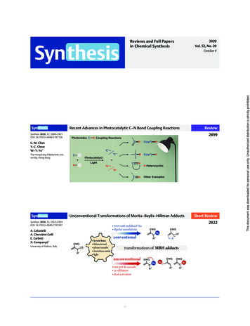
3.4 Floorplanning and Delay Estimation EnginesThe floorplanning stage in a typical design flow arranges arbitrarily shaped, but usually rectangular blocksrepresenting circuit partitions, into a non-overlapping placement while minimizing a cost function, which isusually some linear combination of die area and total wirelength. Our floorplanning engine is adapted from thesimulated annealing based floorplanner proposed in [19]. The input to the floorplanner is a list of components andtheir interconnections in the system. Each component has an area associated with it (obtained from RTLsynthesis). Dimensions in the form of width and height (for “hard” components) or aspect ratio (for “soft”components) are also required for each component. Additionally, maximum die size and fixed locations for hardmacros can also be specified as inputs. Given these inputs, our floorplanner minimizes the cost functionCost w1.Area w2.BusWL w3.TotalWL. (1)where Area is the area of the chip, BusWL is the wire length corresponding to wires connecting components on abus, TotalWL is total wire length for all connections on the chip (including inter-bus connections) and w1, w2, w3are adjustable weights which are used to bias the solution. The floorplanner outputs a non overlapping placementof components from which the wire lengths can be calculated by using half-perimeter of the minimum boundingbox containing all terminals of a wire (HPWL) [20].l1l2(a)lkC2C1RdCkCk-1l(b)RdC0CO (c)CLkCL Cj CLj 1kj 1ji 1lli.C jFigure 2. Transforming multiple pin net into a two pin netOnce the wire lengths have been calculated, the delay estimation engine is invoked. The wire delay iscalculated based on formulations proposed in [21]. The inputs to this stage are the wire lengths from thefloorplanner and the capacitive loads (CL) of component output pins (obtained from RTL synthesis). We cansimplify the multiple pin problem (which is representative of a bus line) depicted in Figure 2(a) to a two pinproblem shown in Figure 2(b). Then the delay for a wire of length l, with optimal wire sizing (OWS) [21], isgiven asα 1l2α 1lT RdCo Rdcf Rdrcacfl .l (2)W 2 ( α 2 l ) W ( α 2l )where α 1 1rc a , α 2 142rc aR dC Land W(x) is Lambert’s W function defined as the value of w whichsatisfies wew x. Rd is the resistance of the driver, l is the wire length, CO and CL are capacitive loads which arecalculated as shown in Figure 2(c) and the rest of the parameters are dependent on the process technology used – ris the sheet resistance in /sq, ca is unit area capacitance in fF/µm2 and cf is unit fringing capacitance in fF/µm(defined to be the sum of fringing and coupling capacitances). The values for these technology dependent6
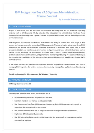
parameters are listed in Table 1, and have been calculated from [22].The delay estimation engine is ultimately used to check for bus cycle time violations in the design. This isillustrated through an example. Figure 3 shows a floorplan for a system where IP1 and IP2 are connected to thesame bus as ASIC1, Mem4, ARM, VIC and DMA, and the bus has a speed of 333 Mhz. This implies that the buscycle time is 3 ns. For a 0.13 µm process and a driver resistance value Rd of 0.4 k , the floorplanner finds a wirelength of 9.9 mm between pins connecting the two IPs to the bus, with CL 2.936 pF and CO 0.988 pF for thewire. The wire delay, obtained by inserting these values in (2), is found to be 3.5 ns. This violates the clock cycletime constraint of 3 ns, and we thus conclude that the bus architecture is not feasible. In this way, ourfloorplanning and delay estimation engines determine if a synthesized design is feasible or not. As we will showlater, our synthesis flow attempts to automatically eliminate such violations once they are detected.Table 1. Parameters based on NTRS 97Tech 130.0810.0460.043IP2IP1Figure 3. Example floorplan3.5 Synthesis ApproachWe now describe our automated synthesis approach in detail. Figure 4 gives a high level overview of theflow. The inputs to the flow include a Communication Throughput Graph (CTG), a target communicationarchitecture (e.g. AMBA), a set of Communication Parameter Constraints ( ) and a library of behavioral IPmodels. The general idea is to first perform preprocessing transformations on the CTG to improve theperformance of the entire system (preprocess) and then map all the components from the CTG to a simple bustopology. Then, we iteratively select a Throughput Constraint Path (TCP), starting from the TCP with the largestconstraint and moving in descending order, from set (which is a superset of all TCPs in the system) and searchthe communication parameter space for a suitable parameter configuration (explore params) and possiblyperform topology mutations if needed (mutate topology) till all TCP constraints are satisfied. Once all TCPconstraints are satisfied, we optimize the design (optimize design) to lower the cost of the system and avoid7
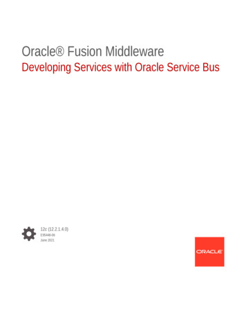
possible timing violations. Next we invoke the floorplanning and delay estimation engines to detect bus cycletime violations. If timing violations are detected, we update and repeat the topology mutation and parameterexploration phase, or proceed to output the synthesized system and floorplan if there is no rarysimplesimple busbusmappingmappingcommcommarch.arch.SelectSelect unsatisfiedunsatisfiedTCPTCP fromfromconstraintconstraintSetSet (( ))outputoutput synthesizedsynthesizedcommunicationcommunication archarchyesnostillstillempty?empty?RunRun floorplannerfloorplannerandand delaydelay estimatorestimatorexplore paramsexplore paramsnoTCPTCPmutate topologymutate topologymet?met?yesnoempty?empty?optimize designoptimize designyesFigure 4. Automated Synthesis FlowFigure 5 shows the pseudo code for the preprocess stage. In the first step we map the components in the CTGfrom the behavioral IP library database to a simple, protocol-independent, transaction-level simulation model inSystemC [24] having a virtual channel for every edge in the graph. This model has no contention since there areno shared channels and also because we assume infinite ports at IP interfaces. The purpose of this step is toobtain, through simulation, a memory usage profile (Step 2). Once we have obtained this profile, we attempt tosplit those memory nodes for which different masters access non-overlapping regions (Step 3). Finally we mergelocal slave nodes with their master nodes to reduce contention and loading on shared busses (Step 4). Note thatwe perform Step 3 before Step 4 because it allows us to generate local memories which can then be merged withtheir corresponding masters.Step 1: Map CTG to protocol-independent TLMStep 2: Simulate designGenerate usage profile for memory modulesStep 3: Split memory nodes wherever applicableStep 4: Merge local memory/slave nodes with master nodesFigure 5. preprocess procedureAfter the preprocessing stage, all the components in the enhanced CTG and the selected bus architecture aremapped from the IP library database to the fast transaction-based bus cycle-accurate simulation model (Section3.2) with a simple bus topology – a single shared main and a single shared peripheral bus. As mentioned earlier,8
every node in a CTG has information relating to the type of bus it can be connected to, which guides the mappingprocess. Once the simple topology is created, we select the largest unsatisfied TCP constraint from setandsearch for a suitable combination of communication parameter values to satisfy the constraint in theexplore params stage. Figure 6 gives the pseudo code for this procedure. explore params searches for a suitablecombination of parameter values which satisfies the TCP constraint under consideration, for the current topology.The parameter values are bounded by the constraint set specified by the designer. However, the explorationspace arising from the combinations of the bounded values can still be very large. In the interest of achievingpractical running times, we set the bus widths and speeds to the maximum allowed values set by the designer in(Step 1). We then select a combination of a valid arbitration priority ordering and DMA burst size, and proceed tosimulate the design (Steps 2, 3). The best result configuration in Step 3 is the combination of parameters forwhich the least number of TCP constraints are violated and the throughput for the TCP being considered is thehighest. The set of valid arbitration priorities is governed by the following rules: (a) priorities of masters in TCPswith larger throughput constraints are always greater than priorities of masters in TCPs with lower throughputconstraints, (b) once a TCP constraint is satisfied, the relative arbitration priority ordering for masters in the TCPis updated (Step 5) and not changed anymore and (c) only combinations of priority orderings within the TCPunder consideration need to be explored if the previous two rules are followed. These three rules reduce the largearbitration space and make it more manageable. The set of valid DMA burst sizes is governed by the followingrule: (a) once a TCP constraint is satisfied, only those DMA burst size values which did not violate the satisfiedTCP constraint are considered for subsequent TCPs. Thus, as TCP constraints are satisfied, the set of valid DMAburst size values shrinks, reducing the DMA burst size exploration space. Figure 6 shows how once a TCPconstraint is satisfied, we simulate the design for different DMA burst size values to generate an updated set ofallowed DMA burst sizes (Step 6) which will be used for subsequent TCP explorations.Step 1: Set bus speed, bus width to maximum allowed in setStep 2: Select a combination of valid arbitration priority ordering and valid DMA burst size.Exit if all valid combinations exhaustedStep 3: Simulate designUpdate best result configurationStep 4: If TCP constraint not satisfied or previously satisfied TCP constraint violated, goto Step 2Step 5: Update and arbitration priority ordering for masters in TCPStep 6: Simulate design for remaining DMA burst sizes and update allowed DMA burst size set.Figure 6. explore params procedureIf the TCP constraint is not satisfied for any combination of communication parameter values, we attempt tochange the communication topology in the mutate topology stage. Figure 7 shows the pseudo code for thisprocedure. To meet TCP constraints, we need to eliminate conflict on shared busses, and this can be done bycreating new busses and migrating IPs, from the TCP being considered, iteratively to the new bus till the conflictis resolved. In mutate topology, we first choose an unselected master in the current TCP, create a new bus andmigrate the master to the new bus (Step 2). In subsequent iterations of mutate topology, we migrate the slaves inthe current TCP to the new bus (Step 3). Once all slaves in the current TCP have been considered for migrationand the TCP is still not satisfied, we check for unselected masters in the current TCP (Step 4). If there are stillunselected masters remaining, we undo all slave migrations since the last master migration, mark the slaves in theTCP as being unselected and migrate a randomly chosen previously unselected master to the new bus (Step 4a). Insubsequent iterations we again migrate the slaves to the new bus (Step 3). After all masters and slaves in thecurrent TCP have been moved to the new bus or at least considered for migration, it is possible that the TCPconstraint is still not met. In that case, we mark all the master and slave IPs in the TCP as unselected, randomlyselect a master on the previously created bus and permanently assign it to that bus, create another bus and startingfrom a randomly selected master, iteratively migrate IPs to that bus (Step 4b). In this way, new busses are createdtill enough bandwidth is available to satisfy the TCP throughput constraint. Note that if a topology mutationcauses the best result configuration from explore params to violate any previously satisfied TCP constraints, weundo the mutation (Step 1). Otherwise we keep the mutation, even if it deteriorates current TCP performance9
slightly. This allows us to take into account the effect of local minima in the exploration phase.Step 1: If previous mutation caused any satisfied TCP constraint to be violated, undo mutationStep 2: If (no master in current TCP selected yet)Create new busGoto Step 6Step3: If (TCP master selected) and (unselected TCP slaves remain)Goto Step 5Step 4: If (all TCP slaves already selected)Step 4a: If (unselected TCP master remains)Undo all slave migrations since last master migrationMark slaves in TCP as unselectedGoto Step 6Step 4b: If (all TCP masters already selected)Mark slaves in TCP as unselectedMark all masters in TCP as unselectedRandomly select master on last created bus, permanently assign master to that busCreate new busGoto Step 6Step 5: Randomly select an unselected slave.Migrate to new bus. ExitStep 6: Randomly select an unselected master.Migrate to new bus. ExitFigure 7. mutate topology procedureOnce all the TCP constraints are satisfied, we arrive at the optimize design stage. The pseudo code for thisstage is given in Figure 8. The purpose of this stage is to reduce the ‘pessimistic’ high values we selected for buswidths and bus clock speeds, to reduce the cost of the final system. Here we iteratively consider each bus in thesystem and attempt to lower the value for bus width (Step 2) and bus clock speed (Step 4), without violating anyTCP constraints. Reducing the bus speed in this stage also helps prevent physical timing violations since itlengthens the bus cycle time.Step 1: Select previously unselected bus from generated bus architectureStep 2: Reduce data bus width to next lower valueSimulate designStep 3: If (TCP constraint violation), undo, else goto step 2Step 4: Reduce bus speed to next lower valueSimulate designStep 5: If (TCP constraint violation), undo, else goto step 4Step 6: If all busses examined, exit, else goto step 1Figure 8. optimize design procedureNext we pass the optimized system through our floorplanning and wire delay estimator engine. If a timingviolation is detected, the set is updated with TCPs which have components on the busses with violations, andwe again go back and attempt to select appropriate parameter value combinations and a different topology whichresolves the timing violations. Changing the topology by migrating IPs to a new bus, in particular, reducescapacitive loading and consequently wire delay on the bus, which is one of the primary causes of timing violationin a design (Section 3.4). Finally, after any violations have been resolved and all TCP constraints satisfied, weoutput the final synthesized bus topology, parameter values for bus speeds, data bus widths, DMA burst size andarbitration priority ordering, along with the feasible floorplan.10
4. CASE STUDIESWe applied our automated bus-based communication architecture synthesis approach on two industrialstrength designs from the network communication domain. In the first case study, we selected a networkcommunication SoC subsystem used for fast data packet processing and forwarding. Figure 9 shows the CTG forthis system. There are two data m
Irvine, CA 92697-3425, USA Newport Beach, CA 92660 USA 1 (949) 824-2248 1 (949) 483-4600 {sudeep, dutt, eli}@cecs.uci.edu m.benromdhane@conexant.com CECS Technical Report #04-27 October, 2004 * This work was partially supported by grants from Conexant Systems Inc. and UC Micro (03-029)