Transcription
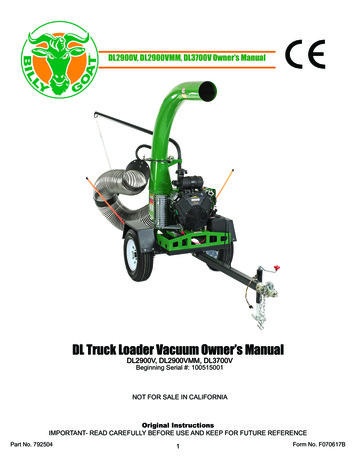
DL2900V, DL2900VMM, DL3700V Owner’s ManualDL Truck Loader Vacuum Owner’s ManualDL2900V, DL2900VMM, DL3700VBeginning Serial #: 100515001NOT FOR SALE IN CALIFORNIAOriginal InstructionsIMPORTANT- READ CAREFULLY BEFORE USE AND KEEP FOR FUTURE REFERENCEPart No. 7925041Form No. F070617B
Table of ContentsSpecifications/Accessories3Instruction Labels/Packing Checklist4Packing 13Troubleshooting14Service Kits15-16Illustrated Parts and Part Lists17-24Declaration of Conformity25-27Part No. 7925042Form No. F070617B
SpecificationsDL2900VDL2900VMMDL3700VEngine: HP29 HP (21.6kW)29 HP (21.6kW)37 HP (27.6kW)Engine: Model5424770004J15424770004J161E3770030J1Engine: TypeBriggs and Stratton VanguardBriggs and Stratton VanguardBriggs and Stratton VanguardEngine: Fuel Capacity6 gal. (22 L)6 gal. (22 L)6 gal. (22 L)Engine: Oil Capacity2.4 qt. (2.3 L)2.4 qt. (2.3 L)2.4 qt. (2.3 L)Total Unit Weight475 lb. (215.5 kg)475 lb. (215.5 kg)475 lb. (215.5 kg)Max. Operating Slope25 25 25 Overall Length60” (1.52m)60” (1.52m)60” (1.52m)Overall Width32.25” (0.82m)32.25” (0.82m)32.25” (0.82m)Overall Height74 7/8” (1.90m)54” (1.37m)74 7/8” (1.90m)In accordance with 2000/14/EEC122 dB(a)122 dB(a)122 dB(a)Sound at Operator’s Position100 dBaVibration at Operator’s Position0.32g (2.96 m/s )100 dBa100 dBa0.32g (2.96 m/s )220.32g (2.96 m/s2)Note: Battery is not included! Your DL requires a 12V battery(40AH, 240CCA min., U1 series group) for proper fit andfunction.AccessoriesHose Replacement KitExhaust Hose KitTrailer DLStandard on DL units. 10’ (3.0m) long, clearpolyurethane hose8” x 5’ (203mm x 1.5m) flexible hoseincreases exhaust distance. 8” x 5’(203mm x1.5m) flexible steel hoseincreases exhaust distance.Heavy duty spring axle trailer designedfor towing your DL. Allows unit to bemounted for pickup from rear.12” Hose P/N 791034 (DL2900V,DL2900VMM)14” Hose P/N 792208 (DL3700V)8” Flexible Hose P/N 7911078” Flexible Steel Hose P/N 791106P/N 791152Part No. 7925043Form No. F070617B
Instruction LabelsThe labels shown below were installed on your BILLY GOAT DL Vacuum. If any labels are damaged ormissing, replace them before operating this equipment. For your convenience in ordering replacement labels,part numbers are included in the Illustrated Parts List. The correct position for each label may be determinedby referring to the Figure and Item numbers shown.Fig. 1DANGER KEEP HANDSAND FEET AWAYP/N 440424Fig 2.WARNING SECUREP/N 790232Fig. 5WARNING LINER DLP/N 100330Fig. 4EXPLOSIVE FUELFig. 3DANGER FLYING DEBRISP/N 810736Fig. 6WARNING ENGINE OVERHEATP/N 811215Fig. 7DL INSTRUCT/WARNP/N 790142Fig. 8SECURE NOZZLEP/N 790232Packing ChecklistYour Billy Goat is shipped from the factory in one carton and is completely assembled except for theexhaust elbow, nozzle, handle loop for nozzle, hose booms, hose bands, hose coupler, hose clampsand related hardware.READ all safety instructions before assembling unit.TAKE CAUTION when removing the unit from the box.PUT OIL IN ENGINE BEFORE STARTINGPart No. 7925044Form No. F070617B
Packing Checklist ContinuedAParts Bag and Literature AssemblyIncludes:ItemWarranty CardOwner’s ManualGeneral Safety and WarningsManualP/N400972792504100294BCEDNOTE: BATTERY IS NOT INCLUDED.REQUIRES 12 V BATTERY, 40 AH, 240 CCAMIN. U1 SERIES GROUP BATTERY FORPROPER FIT.FIGHBoxing Parts Exhaust Elbow791114-S791140791114-SBHose Boom Assembly791113791113791113CBoom Chain791117791117791117D-Clamp T-bolt Overcenter 12” Hose (DL2900V)-Clamp T-bolt Overcenter 14” Hose (DL3700V)791065791065792219E-Band hose boom 12” (DL2900V & DL2900VMM)-Band hose boom 14.50” (DL3700V)790153790153792403FHose 12” X 10” (DL2900V & DL2900VMM)Hose 14”x 10’ DL (DL3700V)791034791034792208G-Hose clamps 12”-Hose clamps 14”790150790150792224H-Nozzle intake 12” (DL2900V)-Nozzle intake 14” (DL3700V)790149-S790149-S792605IHandle Nozzle791116791116791116Parts Bag & Literature Assy792020792020792021Part No. 7925045Form No. F070617B
Packing Checklist ContinuedParts Bag Hardware Includes:Fig. 9AssemblyNOTE: Items in ( ) can be referenced in the Parts Illustration and Parts List on pages 17-24.1. SECURELY ATTACH unit to the bed of a truck or to a trailer, so that the exhaust discharges into anenclosed container. NOTE: This unit must be securely mounted to the bed of a truck or to a trailer beforeoperating.2. ATTACH the hose boom (item 2) to hose (item 3) by sliding the boom through the rings on the top of thehousing.3. ATTACH hose (item 3) to housing intake, using hose clamp (item 25) making sure to place the safety switch under the clamp. Then place the clamp (item 25) over and around the end of the hose to beattached to the housing. Slide the hose onto the housing intake and place the shut off switch under theclamp. Make sure the shut off switch is pressed in or the vacuum will not start, and clamp the hose to theintake. (See page 8 for illustration)4. ASSEMBLE nozzle handle (item 6), to nozzle intake (item 9), using screw (item 7), eye bolt (item 8),washers (item 10) and lock nuts (item 11).5. ATTACH assembled nozzle to hose using hose clamp (item 25). Before tightening hose clamp, positionnozzle handle upward when hose is stretched to prevent twisting. Load on hose assembly during operation.Part No. 7925046Form No. F070617B
Assembly ContinuedNOTE: Items in ( ) can be referenced in the Parts Illustration and Parts List on pages 17-24.6. ASSEMBLE hose band (item 2) around hose and secure chain between the flanges of the hose band usingcapscrew and lock nut (not pictured in Parts Drawing 1). Attach the chain (item 12) to the boom and the screwon the hose band. (See “ADJUSTING HOSE BOOM” on page 11).7. SECURELY ATTACH exhaust elbow (item 31) capturing both flanges inside the clamp, then firmly tightenthe clamp, securing the elbow to the housing (see “MOUNTING” below).8. INSTALL a standard 12 volt lawn and garden battery “U1” series (not included) with at least 240 cold cranking amps anWd a 40 amp hour rating by using battery bracket (item 60), hold down rods (item 59), washersand lock nuts (Not pictured in Parts Drawing 4).9. ATTACH the red battery cable to the terminal and the black battery cable to – terminal on the battery.Mounting Main UnitGeneral: Unit must be securely mounted to atrailer, truck bed, or other similar surface beforeuse. Do not use this unit in a freestanding position. Unit is not stable until it has been securedin place.Secure unit by bolting through the base of theunit and through the mounting surface using3/8" dia. bolts, with washers and locking nuts(see Fig. 10).Mounting: Fig. 11 illustrates the mounting position to the trailer (Billy Goat Part No. 791152)available from your Billy Goat dealer. The unitis only mounted one way.Fig. 10Fig. 11Part No. 7925047Form No. F070617B
Assembly ContinuedMounting Exhaust Elbow (See Fig. 12)Note: this process requires two people, one tosupport the exhaust elbow and one to attachplates and hardware.1. Remove the hardware from the clamps (items30 and 40).2. Apply good quality grease to the top andbottom of the toothed plate of the exhaust elbow(item 31). Also grease top surface of housing andbottom of clamp plates where the gear will rotate.3. Place the exhaust elbow on the chute with theteeth of the flange against the worm gear and theexhaust holes, aligning.4. Place the two bottom plates (item 35) on theopposite edges beside the elbow teeth aligningthe holes.5. Place the top plates (item 34) on top of thelower plates aligning the holes.Fig. 126. Secure the assembly with a plate half on top ofthe elbow flange and a plate half on bottom of thehousing flange using 6, 1” carriage bolts and 6lock nuts (removed hardware in step 1).Part No. 7925048Form No. F070617B
OperationVacuuming OperationImportantWith the machine off and spark plug disconnectedcheck the condition of the replaceable liner beforeevery use and replace if necessary.Exhaust Direction and DistanceExhaust direction and distance are controlled bythe rotation of the exhaust elbow. Typically debris isaimed to discharge to the rear of the container. Thedirection of discharge is adjusted by turning the crankon the exhaust elbow clamp and rotating the elbow tothe desired direction.Fig. 13Note: Elbow is heavy. Use caution when adjusting.Never stand directly under the elbow while adjustingdirection of exhaust. Never direct exhaust into anarea where bystanders may cross the path of thedebris.Intake OperationWith the fully assembled machine running, movethe nozzle in sweeping motions over debris. Alwaysallow air to flow into the nozzle along with the debris.Do not completely block the nozzle when vacuuming,it will reduce performance, and increase clogging(See Fig. 13). For removal of heavier debris, or debristhat is stuck to the ground, rock nozzle forward toconcentrate suction power around the debris (SeeFig. 14).Fig. 14Adjusting Hose BoomProperly adjusting the boom prevents most hoseclogs from occurring and maximizes vacuumperformance by keeping the hose straight andperpendicular to the housing (see Fig. 15). Raiseor lower one of the attachment links to a differentarea on the chain to make height adjustments.A HoseB Hose Band (stretch hose out before clamping).ABFig. 15Part No. 7925049Form No. F070617B
Operation ContinuedUnclogging a Clogged HoseWith engine running and unit secured to a trailer, truck bed, or other similar surface, fullystretch hose in a straight line to dislodge the clog. If the clog will not clear, turn unit off, andallow engine to come to a complete stop. Remove hose and manually clear the hose clog.Note: The clogged debris may be sharp. Always wear durable gloves when removing clogs.Unclogging a Clogged Housing or Exhaust Elbow1. Turn engine off and wait for impeller to come to a complete stop.2. Disconnect spark plug wires and battery cables.3. Remove the hose from the housing and determine where the clog is located.4. If possible, clear the clog through the intake opening. It may require removal of the intakeadaptor (item 6) to allow access to clear the housing.5. If clog is in the elbow, carefully remove the elbow. Remove elbow by removing the boltsand nuts on the elbow clamp so that the plates can be removed.Note: Elbow is very heavy. Do not stand directly under elbow during removal!Danger: The clog may contain sharp materials. Clear the clog wearing durable gloves!Reconnect spark plug wire.Hose CareTo increase hose life, periodically rotate hose and reposition nozzle and coupler on frontplate of unit. This ensures that the hose will not wear on only one side, further increasing itslife.Keep hose as straight as possible and avoid sharp bends during operation for best pick-upand to avoid clogs. Never drag hose. Always remove and store hose before transportingunit. Store hose straight and flat to maintain flexibility for next use.MaintenanceInterlock SystemWith hose coupler installed (as shown in Fig. 16) theswitch is open and engine is not grounded out, allowing engine to run. Hose must be installed and switchlever must engage switch for engine to start.Fig. 16Part No. 79250410Form No. F070617B
Maintenance ContinuedImpeller Removal1. Wait for engine to cool and disconnect spark plug wires from the bothsides of the engine.2. Disconnect the negative battery cable (black) (item 89) from the battery.3. Remove the hose from the unit.4. Unattach the hose from boom assembly.5. Remove the intake housing assembly (item 11) using 9/16” socket andsocket wrench to remove (12) locknuts (item 55). Be careful to place intakeassembly to the side without putting excess strain onsafety switch wire harness.Fig. 176. Remove impeller bolt and lock washer by using an impact wrench (see Fig. 17).7. Once bolt is removed impeller should slide out freely.8. When impeller is free of the engine shaft, align impeller with the opening and pull it straight out of the housing.9. Using a new impeller bolt, washer, and lock washer, install new impeller in reverse order.10. Tighten impeller bolt. Torque impeller bolt to [175-180 Ft. Lbs. (237-244 N.m)].11. Repeat steps 2 through 5 in reverse order.12. Reinstall spark plug wires.Battery Care (For Electric-Starting Models)Proper care can extend the life of a battery. Follow these recommendations to ensure your battery’s best performance and long life: Do not allow the battery charge to get too low. If the machine is not used, charge the battery every 4 – 6 weekswith a 2 amp battery charger. Operate the engine for at least 45 minutes to maintain proper battery charge. Store an unused battery in a dry area that does not freeze. Do not charge an already charged battery. In theory, you cannot overcharge our battery with a tricklecharger; however, when a battery is fully charged and the charger is still on, it generates heat thatcould be harmful to the battery. A fully charged battery will read 12V-13.2V with a voltmeter. Do not continue to crank your engine when the battery charge is low.Charging the BatteryOperate the engine for at least 45 minutes to maintain proper battery charge. If the battery loses its charge, you willneed to use a trickle charger to recharge it. Caution: The charger should have an output of 12 volts at no more than2 amps. Using a charger with higher amps will cause significant damage to the battery. At 1 amp, the battery may need charging for as long as 48 hours. At 2 amps, the battery may need charging for as long as 24 hours.Part No. 79250411Form No. F070617B
Maintenance ContinuedWiring DiagramPart No. 79250412Form No. F070617B
Maintenance ContinuedPeriodic MaintenanceMaintenance OperationCheck engine oilEngine OilChange engine oilCheck air filterAir FilterClean air filterEachUse Every 20 Every 50Hr or First Hrs or 3MonthMonths Replace air filterCheck/Adjust spark plugSpark PlugBatteryReplace spark plug Check replaceable liner Check and clean engine of debrisClean hoseInspect for loose, worn ordamaged partsCheck for excessive vibrationClean truck loaderCheck condition of fuel linesCheck all hardware for tightnessEvery250HrsEvery300Hrs ** Inspect battery for corrosion orleaksCheck battery terminal forcorrosionCheck/adjust valve clearanceEvery 100Hrs or 6Months * * Or as needed.** Or more often when used in dusty conditions.Part No. 79250413Form No. F070617B
TroubleshootingProblemPossible CauseSolutionWill not vacuum or has poor Nozzle buried in debris.vacuum performance Clogged hose or exhaust. Excessive quantity of debris. Withdraw nozzle from debris pile. Unclog hose or exhaust (See page 12)Engine will not start.(Starter does not turn). Battery is low or dead. Battery cable is disconnected or battery terminal is corrroded. Harness wire is bad or disconnectedfrom interlock switch. Hose not installed, allowing interlockwire to ground. Charge batter or replace if the batterydoes not hold charge. Clean battery terminal and cable thenreconnect. Install hose coupler securely to the unitand check whether interlock sitch is engaged by lever. Check harness wire connection.Enging will not start.(Starter turns). Throttle and/or stop switch in off position. Out of gasoline. Bad or old gasoline.Spark plug wire disconnected. Dirty aircleaner. Check stop switches, throttle, and gasoline. Connect spark lug wire. Clean or replace air cleaner. Or contact qualified service personelle.Engine is locked and willnot pull over. Debris locked against impeller. Engine problem. See page 12: “Unclogging a cloggedhousing or exhaust elbow.” Contact an engine servicing dealer forengine problems.Engine will not stay running. Oil reservoir overfilled.Part No. 792504Drain oil and refill to correct level.14Form No. F070617B
Service KitsSome parts on your BILLY GOAT DL Vacuum can be serviced through at-home maintenance with a servicekit. You can purchase a service kit by contacting BILLY GOAT customer service. Below is a list of service kitsavailable for the BILLY GOAT DL Vacuums and items that each service kit includes.Housing Service Kit-Available for all DL models under P/N 792600Part G WA DL29/37LABEL DL PIRANHALABEL PRODUCT DECAL DLLABEL DL INSTRUCTION/WARNLABEL WARNING ENGINE OVERHEATQuantity11111Engine Base Service Kit-Available for all DL models under P/N 792604Part No.792106790232100164DescriptionBASE ENGINE WA DL35LABEL WARNING SECURELABEL PRODUCT DECAL DLQuantity111Muffler Assembly Service Kit-Available for all DL models under P/N 792607Part No.792226DescriptionMUFFLER ASSY DL35Quantity1Flapper Intake Service Kit-Available for DL2900V & DL2900VMM models under P/N 791103-S-Available for DL3700V under P/N 792603Part No.792105400424Part No. 792504DescriptionFLAPPER WA 14” INTAKE DL35LABEL WARNING OPEIQuantity1115Form No. F070617B
Service KitsImpeller Service Kit (P/N 792606)-Available for DL2900V & DL2900VMM models under P/N 792606-Not available for DL3700VPart No.792251792104792222DescriptionIMPELLER WA 20.00” X 1.4375” LOADER DL29PIRANHA BLADE WA DL35SCREWCAP 5/8”-18 X 3.00” ZP GR8Quantity11192012008171010100347KEY 3/8” SQ. X 4.50”WASHER LOCK 5/8 S/T MEDLIT GENERAL 3/4”-16 IMPELLER KIT111Impeller Assembly Service Kit-Not available for DL2900V or DL2900VMM models-Available for DL3700V under P/N 792601Part No.792102792104792222DescriptionIMPELLER WA 20.00” x 1.4375” LOADER DL35PIRANHA BLADE WA DL35SCREWCAP 5/8”-18 X 3.00” ZP GR8Quantity1119201200KEY 3/8” SQ. X 4.50”18171010WASHER LOCK 5/8 S/T MED1100347LIT GENERAL 3/4”-16 IMPELLER KIT1Nozzle Intake Service Kit-Available for DL2900V & DL2900VMM models under P/N 790149-S-Available for DL3700V under P/N 792605Part No.792402811215790301Part No. 792504DescriptionNOZZLE INTAKE FORMED 14”LABEL WARNING ENGINE OVERHEATLABEL WARNING NOZZLE16Quantity111Form No. F070617B
Parts Drawing 1Part No. 79250417Form No. F070617B
Parts List 1Item No.DescriptionDL29000VDL2900VMMDL3700VPart No.Part No.Part No.1HOOK, SNAP SAFETY 5/16” ZP7910277910272BAND HOSE BOOM 12” FORMED 790153790153BAND HOSE BOOM 14.50”FORMED3791027Quantity27924031--1HOSE INTAKE 12”X 10’791034791034HOSE 14” INTAKE x 10’--7922081-14GRIP 1-1/4” ID x 9.5” LONG44014644014644014625PLUG TUBE INSERT 1.25” O.D.79105679105679105626HANDLE NOZZLE DEBRISLOADER79105479105479105417SCREWCAP 3/8”-16 X 2” HCS ZP80410548041054804105418BOLT EYE G-2 3/8” x 2”791081791081791081110WASHER 3/8 FC 7/16 X 1 X 5/64817100481710048171004611NUT LOCK 3/8-16 HEX816000381600038160003212CHAIN 73 LINKS DL791057791057791057125-CLAMP HOSE 12”790150790150--7922241CLAMP, DIXON HS248-137HANDLE NOZZLE/GRIP ASSY791116791116791116142NUT-HEX-NYLK, FLG .375”-16 ZP816500381650038165003167LABEL WARNING NOZZLE790301790301790301168LABEL WARNING ENGINEOVERHEAT811215811215811215169NOZZLE INTAKE 12” SERVICE790197-S790197-SNOZZLE 14” INTAKE SERVICE76Part No. 792504SCREWCAP 3/8”-16 X 3” HCS ZP--8041058804105818792605180410581Form No. F070617B
Parts Drawing 2Part No. 79250419Form No. F070617B
Parts List 2DL29000VDL2900VMMItem No.DescriptionPart No.Part No.13FLAPPER WA 12” SERVICE791103-S791103-SFLAPPER INTAKE 14” W/LABELSDL3700VPart No.-Quantity1--792603114LEVER HOSE SWITCH791068791068791068116NUT 3/8-16 SER. HEX WSHRFLNG7910797910797910791217BOLT CARRIAGE 5/16-18 X 31/2” ZP802405080240508024050118SPACER 3/8” X 2 1/2”900503900503900503119NUT-HEX-NYLK, FLG .3125”-18ZP816500281650028165002120-INTAKE HOUSING WA 12” DL29 792107-1INTAKE HOUSING WA 14”LOADER DL35 (DL3700V)792107--792103121SCREWCAP 5/8”-18 X 3.00” ZPGR8792222792222792222122WASHER LOCK 5/8 S/T MED817101081710108171010123IMPELLER WA 20.00” X 1.4375”LOADER DL29792251792251-1IMPELLER WA 20.00” x 1.4375”LOADER DL35--CLAMP T-BOLT OVERCENTER12” HOSE791065791065CLAMP T-BOLT OVERCENTER14” HOSE--792219126SCREWCAP 7/16”-14 X 2” GR.5W/PATCH LOCK790307790307790307227WASHER LOCK 7/16” TWISTEDTOOTH850132850132850132228PIRANHA BLADE WA DL35792104792104792104170LABEL WARNING OPEI400424400424400424171CLAMP ROUTING FUEL LINE791070791070791070172HARNESS, WIRING DL791096791096791096173STRAIN RELIEF HEYCO 1244500282500282500282174KEY 3/8” SQ. X 4.50”920120092012009201200175SWITCH, SAFETY INTERLOCK791095791095791095177PIN SAFETY800365800365800365196IMPELLER WA DL29 SERVICE792606792606--24IMPELLER WA 20.00” DL35/DL37Part No. 792504207921021-792601111Form No. F070617B
Parts Drawing 3Note: Items 19, 42, 44, 47, 48, 49, and 78are located in the interior of Item 45.Form No. F070617B21Part No. 792504
Parts List 3DL29000VDL2900VMMDL3700VItem No.DescriptionPart No.Part No.Part No.Quantity29BOOM HOSE HANGER791113791113791113130BOLT CARRIAGE 5/16-18 X 3/4” ZP802403980240398024039631ELBOW 8” DL SERVICE791114-ELBOW EXHAUST WA DL 12” RADIUS7911141-1-79114032LABEL WARNING OPEI400424400424400424133LABEL DANGER FLYING DEBRIS810736810736810736134PLATE CLAMP HALF DL791047791047791047235PLATE CLAMP SPLIT DL791049791049791049236HOURMETER, INDUCTIVE PANELMOUNT373305373305373305138LYNCH PIN 3/16” x 1 9/16”520004520004520004139LANYARD PLASTIC 10”360243360243360243140NUT-HEX-NYLK, FLG .3125”-18 ZP816500281650028165002641GEAR WORM EXHAUST ROTATE791109791109791109142NUT-HEX-NYLK, FLG .375”-16 ZP816500381650038165003443SHAFT GEAR WORM791038791038791038144PLATE FLANGE HOUSING LOADER791020791020791020145HOUSING WA DL29/37792108792108792108147LINER REPLACEABLE LOADER791018791018791018148WASHER 5/16 SAE Z/P8172008817200881720081049SCREW BUTTON HEAD 5/16 X 0.757910787910787910781078BLT-RDHDSSQNK, .375”-16 X 1.000G5 ZP802405880240588024058279WIRE, ASSY HOUR METER DL29/37792256792256792256180GROMMET 1” HOLE520087520087520087181LABEL DL INSTRUCTION/WARN790142790142790142182PIN ROLL 3/16 x 0.875 ZP819516281951628195162183BOOM LOOP HOSE HANGER7910537910537910531Part No. 79250422Form No. F070617B
Parts Drawing 4Part No. 79250423Form No. F070617B
Parts List 4DL29000VDL2900VMMDL3700VItem No.DescriptionPart No.Part No.Part No.Quantity15GUARD MUFFLER DL35792226-2792226-2792226-2119NUT-HEX-NYLK, FLG .3125”-18 ZP8165002816500281650021045HOUSING WA DL29/37792108792108792108146SER. HEX WSHR FLNG SCR 0.375 - 16 x 0.75791080791080791080850MUFFLER ASSY DL29/37792253792253792253151RAKE HOLDER, LOWER DL792244792244792244152TANK, CARB/EPA SIX GALLON 2.500” NECK791157791157791157153CAP, CARB/EPA 3.500”791158791158791158154ENGINE 29HP HORZ. SHAFT B&S792246792246--ENGINE 37HP EFI HORZ. SHAFT B&S-1792247155MANIFOLD DL35792226-3792226-3792226-3156MUFFLER DL29/37792252792252792252157WASHER 5/16 FLAT ZP817100381710038171003458SIDE, ENGINE BASE RH792106792106792106159ROD BATTERY HOLD DOWN790231790231790231260BRACKET BATTERY DL790230790230790230161SCREWCAP 5/16”-18 X 2 1/4” GR 5 HCS ZP804103380410338041033462BUSHING, SNAP 1.81” ID382292382292382292863CLAMP, TANK FUEL791043791043791043264RAKE HOLDER, UPPER DL792243792243792243165BOLT CARRIAGE 1/4-20 X 1 3/4” ZP802402580240258024025266NUT-HEX-NYLK, FLG .250”-20 ZP816500181650018165001284BOLT CARRIAGE 5/16-18 X 3/4” ZP802403980240398024039285CABLE BATTERY BLACK 20”812341812341812341186CABLE BATTERY RED 36”812282812282812282187FUEL LINE 1/4” ID X 6”7924067924067924064881/4” X 1/4” X 1/4” BARB TEE FITTING792255792255792255189FUEL FILTER BRIGGS844793844793844793190CLAMP, FUEL LINE 0.50”791164791164791164891PLUG OIL DRAIN DL35792234792234792234192CLAMP MUFFLER DL35792226-4792226-4792226-4193O2 SENSOR PORT PLUG DL29792254792254792254194GSKT CRUSHABLE CPR 12MM X 18MM X2MM THK792245792245792245195SCREW MUFFLER DL35792226-5792226-5792226-5497DL 29/35/37 MUFFLER ASSY SERVICE7926077926077926071Part No. 79250424Form No. F070617B
en EC Declaration of Conformitybg Декларация за съответствие с европейскитестандартиcs ES Prohlášení o shoděda EC Overensstemmelseserklæringde EG-Konformitätserklärunges Declaración de Conformidad de la CEetEü vastavustunnistusfiEC- vaatimustenmukaisuusvakuutusfrDéclaration de conformité CEenbgcsdadeesetfifrCategorySod CutterКатегория копка КътърKategoriedrnu Rezací ústrojíKategorigræstørv IlderKategorieSodenschneiderCategoríaSod cortadorKategooría mätas kutterKategoriaSod CutterCatégoriede gazon CoupeenbgcsdadeesetEnglishбългарски езикČeštinaDanskDeutschEspañoleesti keelelhuhritltlvnlnoΔήλωση συμμόρφωσης ΕΚEU Megfelelőségi nyilatkozatEC Deklaracija o sukladnostiDichiarazione di conformità CEEB atitikties deklaracijaEK Atbilstības deklarācijaE.G, ConformiteitverklaringCE �οιμου χλοοτάπητα ΚάτερGyep Cutterbusen rezačapiota di taglierinaaeratoriusDanga pjaustyklėplaggenstekergresstorv ийSlovenščinaSlovákSvenskaTürkçeDeklaracja zgodności UEDeclaração de Conformidade à CEDeclaraţie de conformitate C.E.Заявление о соответствии стандартам и нормам ЕСES izjava o skladnostiVyhlásenie o zhodeEG-försäkran om överensstämmelseEC Uygunluk iKategoridarń do kosiareksod cortadorSod de concasorдерново резакrušo rezalecsod Cutterlspadtaget Klippareçim KesicienThis is to certify that the products listed in this document meet the requirements of the European Community Law, and can carry the CE mark.These models comply with the following Directives and related Standards.bgДекларацията се издава в удостоверение на това, че изброените продукти съответстват на стандартите на правните норми на Европейския съюз имогат да носят знака CE. Моделите изпълняват директивите и техните стандарти, както следва.csTímto stvrzujeme, že výrobky uvedené v tomto dokladu splňují požadavky zákonů Evropského společenství a mohou býtoznačeny značkou CE. Tyto modely splňují následující směrnice a související normy.daDet bekræftes hermed, at de produkter, der er nævnt i dette dokument, opfylder bestemmelserne i EU-lovgivningen og kan bære CE-mærkatet.Disse modeller er i overensstemmelse med følgende direktiver og relaterede standarder:deHiermit wird bescheinigt, dass die in diesem Dokument aufgeführten Produkte mit den gesetzlichen Bestimmungen der Europäischen Gemeinschaft übereinstimmenund das CE- Zeichen tragen können. Diese Modelle erfüllen die folgenden Richtlinien sowie weitere anzuwendende Normen.esLa presente certifica que los productos enumerados en este documento cumplen con los requerimientos de la Legislación de la Comunidad Europea, y que pueden portar la marca CE.Estos modelos cumplen con las siguientes Directrices y Estándares relacionados:etKinnitame,et eespool nimetatud tooted vastavad Euroopa Ühenduse seadusandluse nõuetele ja kannavad CE-märgistust. Eespool nimetatud mudelid vastavad järgmisteledirektiividele ja seotud standardile:fiVakuutamme, että tässä asiakirjassa luetellut tuotteet täyttävät Euroopan Unionin lainsäädännön asettamat vaatimukset ja voi saada CE-merkinnän.Nämä mallit täyttävät seuraavien direktiivien ja niitä koskevien standardien vaatimukset:frNous déclarons par la présente que les produits mentionnés dans le document sont conformes à la législation de la Communauté européenne et peuvent porter le marquage CE.Ces modèles sont conformes aux directives suivantes et aux normes connexes :elΜε την παρούσα δήλωση πιστοποιείται ότι τα προϊόντα που αναφέρονται στην παρούσα πληρούν τις απαιτήσεις της Ευρωπαϊκής Κοινοτικής Νομοθεσίας και μπορούν να φέρουν τησήμανση CE. Τα μοντέλα αυτά συμμορφώνονται με τις ακόλουθες Οδηγίες και τα σχετικά Πρότυπα.huEz annak tanúsítására szolgál, hogy e dokumentumban felsorolt termékek megfelelnek az Európai közösségi jog követelményeinek és viselheti a CE jelzést.Ezek a modellek eleget tesznek a következő irányelveknek és vonatkozó szabványoknak.hrOvo je potvrda da proizvodi koji su navedeni u ovom dokumentu odgovaraju zakonima europske zajednice i da nose CE oznaku.Ovi modeli zadovoljavaju sljedeće direktive i odgovarajuće standarde.itSi certifica che i prodotti elencati nel presente documento soddisfano i requisiti della legislazione della Comunità Europea e possono recare il marchio CE.Questi modelli sono conformi alle seguenti norme e direttive:ltŠiuo patvirtiname kad šiame dokumente paminėti produktai atitinka Europos Bendrijos Įstatymų reikalavimus ir jie gali būti pažymėti CE ženklu.Šie modeliai atitinka sekančias direktyvas ir standartus.lvAr šo tiek apstiprināts, ka šajā dokumentā uzskaitītie izstrādājumi atbilst Eiropas Kopienas Likuma prasībām un var tikt marķēti ar emblēmu CE.Šie modeļi atbilsts sekojošajām Direktīvām un attiecīgajām Normām.nlHiermee wordt gecertificeerd dat de producten die in deze lijst staan opgesomd, voldoen aan de wettelijke voorschriften van de Europese Gemeenschap en mogen wordenvoorzien van de CE markering. Deze modellen voldoen aan de volgende richtlijnen en bijbehorende normen:noDette sertifiserer at produktene som er nevnt i dette dokumentet oppfyller kravene som stilles av EU, og at de dermed kan CE-merkes.Disse modellene tilfredsstiller følgende direktiver og relaterte standarder:plNiniejszym zaświadcza się, że produkty wymienione w niniejszym dokumencie spełniają wymogi Prawa Wspólnoty Europejskiej i mogą nosićoznakowanie CE. Modele te spełniają wymogi następujących dyrektyw i powiązanych norm.ptO presente documento certifica que os produtos listados neste documento atendem aos requisitos das Leis da Comunidade Européia e podem levar a marca CE.Esses modelos estão de acordo com as seguintes diretivas e padrões relacionados.roPrin prezenta se atestă faptul că produsele menţionate în acest document îndeplinesc cerinţele de Drept Comunitar European şi potpurta sigla C.E. Aceste modele sunt în conformitate cu următoarele directive şi standarde asociate.ruНастоящим удостоверяется, что перечисленные в этом документе изделия соответствуют требованиям законов Европейского Союза и могут бытьобозначены знаком CE. Эти модели отвечают требованиям следующих директив и соотве
1. SECURELY ATTACH unit to the bed of a truck or to a trailer, so that the exhaust discharges into an enclosed container. NOTE: This unit must be securely mounted to the bed of a truck or to a trailer before operating. 2. ATTACH the hose boom (item 2) to hose (item 3) by sliding the boom through the rings on the top of the housing. 3. ATTACH .