Transcription
Basic Cyclone DesignBill Heumann
Introduction Brief history What is a cyclone?– A device that separates particulate from gas(fluid) by centrifugal force– Works simply by the kinetic energy of theincoming mixture (flow stream) and thegeometry of the cyclone
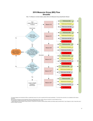
How CyclonesWork:NomenclatureOutlet Pipe/VortexFinder
How cyclones work All cyclones work by centrifugal force Two main factors affect cyclone efficiency– velocity particle moves towards the wall orcollection area of the cyclone where it istheoretically collected– length of time available for collection: ResidenceTime Two main metrics describe cyclone performance– Pressure drop– Fractional efficiency curve (FEC)
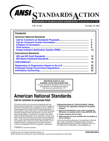
How Cyclones Work: Basic FlowPatterns (Reverse Flow Cyclone)
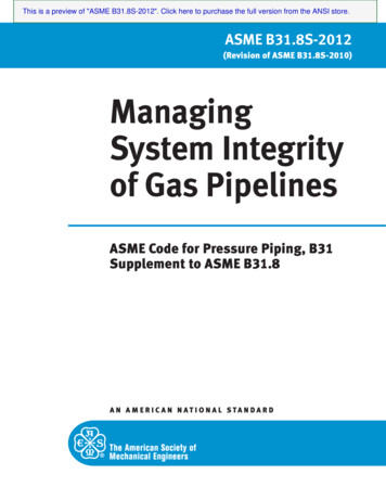
Another Kind of Cyclone
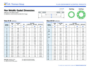
How Cyclones Work: BasicFlow/Pressure ure
Different styles of Cyclones: InletDesigns
Different Arrangements ofCyclonesParallelArrangement
DifferentArrangements ofCyclones: SeriesArrangement
Parallel Cyclones
ParallelCyclones
Different styles of cyclonicdevicesParallel CyclonesReverse FlowAxial Inlet
Series Cyclone Arrangement
FCC Process:The heart ofthe system
FCC Regenerator Cyclones
Pressure VesselCyclones
A cyclone picture of another sort.
Why Use Cyclones? DryNo moving partsRobust ConstructionCan be easily designed for very severeduty (examples) Low cost (sometimes) Safety
When do you use a cyclone? When it is the most economical solution!–––––––––Capital CostsInstallation CostsOperating ExpensesMaintenance ExpenseDepreciation (life expectancy)Safety and liability issueProduct recoverySystem operabilityEffects on downstream equipment and process
Cyclone Performance Metrics:Pressure drop Pressure drop power consumption Pressure drop measurement a inlet - a outletwhere; cyclone pressure drop a absolute pressure
Where Does Pressure Drop ComeFrom? Frictional andentrance lossesusually 10%-30%of total The rest is thepressure gradientgenerated by thevortex
Pressure drop @ no load Basic pressure drop equationE ( Q2/Q1) ( / 1)where;Q gas flow rateE geometry exponent (1.9-2.3) gas density
Pressure drop @ load Pressure drop goes down with increaseddust load Pressure drop dust loading equation L C 0C 2.095 W -.02 -1.09where; L pressure drop @ load 0 pressure drop @ no loadW dust load (grains/acf)
Fractional efficiencies collection efficiency @ various particlesizes fractional or size efficiency curve may be graphical or tabular
Example Size Efficiency CurveParticle Diameter(microns)% collection(B.W)153745921098.743099.45099.810099.99
FEC Variables Cyclone GeometryCyclone VelocitiesParticle DensityGas ViscosityDust Load
Cyclone Total Collection Efficiency Function of the cyclone FEC and incomingParticle Size Distribution (PSD) Cyclone Total Collection Efficiency canvary greatly but it may be doing exactly thesame thing!
Total collection efficiencysample calculationparticlesize rangeparticle sizefractional ected particulateminmax(% by weight)(microns)(% by weight)(% by 002.00Totals10097.21
Tools for Increased Cyclone Efficiency:Cyclone Geometry Variables Inlet configuration and ratioCyclone L/D RatioOutlet pipe penetrationDust receiverResidence time
Tools for Increased CycloneEfficiency: High Residence TimeHigh Capacity/Low ResidenceTimeHigh ResidenceTime/Low Capacity
Tools for Increased Cyclone Efficiency:Parallel Cyclone Arrangements One of best tools for gettinghigher collection efficiency: Fora given power consumptionand family of cyclones, splittingthe flow into parallel streamsallows the use of more efficient,smaller cyclones: “SmallCyclones are more efficientthan large ones.” Parallel arrangements mayprovide the best solution whenheadroom is limited
Tools for Increased Cyclone Efficiency:Parallel Cyclone Arrangements
Tools for Increased Cyclone Efficiency:Series Cyclone Arrangements Can provide highercollection efficiency for alimited inlet velocitybecause of thecumulative efficiency:90% @ 5 micron 90%@ 5 micron 99% @ 5micron May provide forredundancy in the eventof system upsets
Tools for Increased Cyclone Efficiency:Tangential (Radial) VelocityFc m Vt2/rVELOCITY VS. FORCE180160140120TANGENTIALVELOCITY (M/S)CENTRIFUGALFORCE (G'S)10080604020000.5CL DISTANCE (METERS)1
Tools for Increased CycloneEfficiency: Tangential Velocityand/or Centrifugal Force How do we increase Tangential Velocity?– Increase Inlet Velocity– Increase Outlet Velocity What else can we do to increaseCentrifugal Force?– Smaller radius flow path: Use parallelcyclones– Decrease outlet pipe diameter
Other Tools for IncreasedEfficiency: Geometry L/D RatioInlet DesignOptimum Outlet Pipe LengthDust Receivers
Other Tools for IncreasedEfficiency: Arrangement Cyclones in Parallel– Takes advantage of rule that says “forcyclones of the same family (geometricallyproportional) at the same operatingconditions, smaller cyclones are moreefficient than larger ones Cyclones in Series– Redundant chances for particle collection
The Costs of Increased Efficiency:High Residence Time Cyclones Capital Cost Headroom May not be possible orviable with someprocesses
The Costs of Increased Efficiency:Parallel Cyclones Capital Costs Manifolding can be expensive and difficult Pneumatic isolation can be difficult or costprohibitive More horizontal space required
The Costs of Increased Efficiency:Series Cyclones Capital CostsManifolding can be expensive and difficultMore horizontal space requiredPressure Drop is CumulativeDiminished benefit as PSD gets smaller
The Costs of Increased Efficiency:Increased Velocity Pressure Drop (Power Consumption)ErosionParticle AttritionRe-entrainmentAt very high velocities may haveacoustical and/or Ranque-Hilsch effects
How Cyclones Fail Improperly Designed– Incorrect or inaccurate design data– Lack of know how by cyclone designer- after all,“anyone can build a cyclone” Leakage into the cyclone Plugged cyclones Cyclones wear out too quickly
How Cyclones Fail: Design/Fabrication Errors No dust receiverShort outlet pipesDished headsPoor or non existent airlocksInstruments or access ports installed intocyclonic flow streams Related equipment not designed for cyclonicflow Inlet elbows, transitions, or other obstructions
For More Information Visitwww.heumannenviro.com Contact:Bill Heumann4898 Brownsboro Road, Suite 300Louisville, KY 40207PH: 502.742.9677Mobile: 502.396.4297wlh@heumannenviro.com
How Cyclones Fail: Design/ Fabrication Errors No dust receiver Short outlet pipes Dished heads Poor or non existent airlocks Instruments or access ports installed into cyclonic flow strea