Transcription
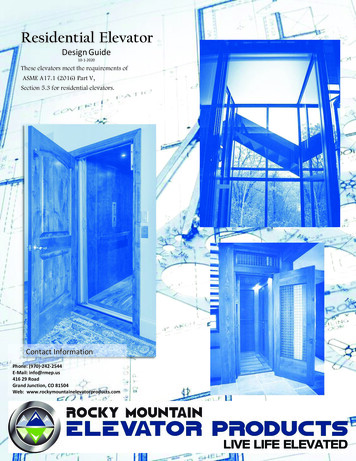
Residential ElevatorDesign Guide10-1-2020These elevators meet the requirements ofASME A17.1 (2016) Part V,Section 5.3 for residential elevators.Contact InformationPhone: (970)-242-2544E-Mail: info@rmep.us416 29 RoadGrand Junction, CO 81504Web: www.rockymountainelevatorproducts.com1
ContentsINTRODUCTION. 3ADVANTAGES . 3NEW RESIDENTIAL ELEVATOR SAFETY AS MANDATED BY THE NATIONAL CODE . 4HOISTWAY DOOR LAYOUT . 4CHART FOR ROUGH OPENING . 4¾” CLEARANCE/FLUSH HOISTWAY DOOR FRAMES . 5PRE-PLANNING STEPS . 7REQUIRED OVERHEAD . 9HOISTWAY ILLUSTRATION . 10MACHINE ROOM DESIGNS AND CONTROLLER SPACE . 11STEPS TO PLANNING YOUR HOME ELEVATOR . 12Drive Systems Overview (Step 1). 12Standard Car Layouts (Step 2). 13Gate Styles (Step 3). 13Hoistway/Entrance Doors (Step 4) . 13Car Sizes (Common Sizes Shown) (Step 5) . 13HOISTWAY LAYOUTS (STEP 6) . 14WORK BY OTHERS. 22About Rocky Mountain Elevator ProductsRMEP started out 25 years ago installing and servicing elevators, we saw the need for a higher quality productwith more options and features. We set out to create a higher level of safety and quality product with more options andfeatures. We set out to create a higher level of safety and drew on our 25 years of knowledge and experience of whatthe best and worst ideas we have seen and serviced. We incorporated only the best along with new innovations to offerthe best product the consumer can find.Mission StatementAt Rocky Mountain Elevator Products LLC it is our mission to improve safety and customer experience by providing asuperior level of design and innovation. We aspire to create industry-wide change by setting a higher level of excellenceand always exceeding customer expectations.2
INTRODUCTIONThis Planning Guide is to be used only as a reference to determine parameters of installation and the steps to achieve aproper elevator installation. This guide may be used by the architect, contractor, dealer or homeowner. The information inthis guide is intended as an overview. Each installation will have site-specific specifications that must be followed. Donot attempt to construct a hoistway on this information. Before beginning actual construction, be sure you have andfollow specific shop drawings engineered to fit your site conditions.The dimensions and specifications in this planning guide are subject to constant change, without notice, due toproduct enhancements and continually evolving codes.Elevator installation must be done by an authorized elevator contractor, and in accordance with engineered drawingsprovided by the manufacturer. Installation must also be in compliance with requirements of the National ElectricCode, American Society of Mechanical Engineer’s safety code, and local building codes. We strongly recommend youcontact the code authority in the jurisdiction where the elevator will be installed. Rocky Mountain Elevator’s productsare designed to meet the requirements of the most recent ASME - A17.1 Part V Section 5 for residential elevators.Rocky Mountain Elevator’s products are warrantied for 3 years after meeting the above codes. Rocky Mountain ElevatorProducts assumes no liability for equipment not installed in compliance with these codes.ADVANTAGES Machine Room-Less (MRL) available, please see MRL Planning Guide.2-6 stops, up to 50 feet.More options and features than any other manufacturer.Gate systems are 2016 code compliant for child safety.Superior and customizable design.Superior innovation.Multiple drive options.Plug and play wiring system for fast installation.Pre-tested components to ensure reliability.Smooth and quiet operation: Smooth Ride technology using the industry’s best self-adjusting valves on hydraulicmodels.On-board LCD screen with self-diagnosis for quick and easy troubleshooting.Low Maintenance: the elevator is designed for minimal maintenance; the visual service alert and fault codes will tellyou when it’s time to consider a service inspection.All models have emergency battery lowering and lighting in case of power interruption.Stylish and modern: Our smooth stylish features are timeless and will blend with any décor for years to come. Thefixtures feature long life LED push buttons for that classic elevator feel right in your own home!MADE IN USA3GREEN MANUFACTURING
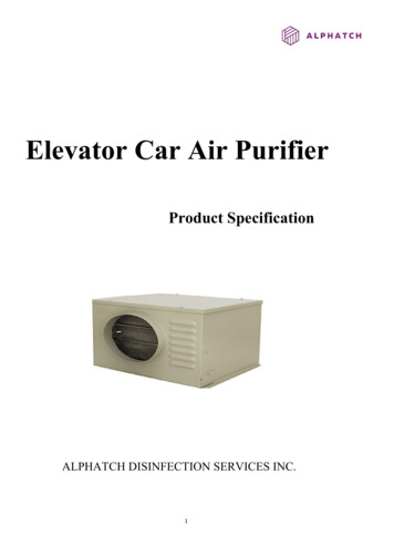
y code complainant elevator per the ASME ANSI A17.1 NationalNEW RESIDENTIAL ELEVATOR SAFETY AS MANDATED BY THE NATIONAL CODEnces Elevatorsas modifiedby various states.FOR ENHANCEDCHILD SAFETY.ASME 5.3.7.2: code clearance between the hoistway doors or gates and the landings sills and car doors or gateseffective May 2016.Clearance requirements within a private residence state: The clearance between the hoistway doors or gates andthe hoistway face of the landing door or gate and the car door or gate shall not exceed ¾” (0.75 Inches). Thedistance between the hoistway face of the landing door or gate and the car door or gate shall not exceed 4”(inches).earance between the hoistway doors or gates and the landingsance requirements within a private residence state: Thehe hoistway face of the landing door or gate and the car door oretweenthe hoistwayface of the landing door or gate and theHOISTWAYDOOR LAYOUTas the (3”x5” rule)NEW RESIDENTIAL ELEVATOR SAFETY AS MANDATED BY THE NATIONAL CODEtrapment.FOR ENHANCED CHILDFigureSAFETY.1:Illistration of actual 6 y.o. entrapment.ASME 5.3.7.2: code clearancebetweenthewithhoistwaydoors or gates and the landings sills and car doors or gatesImageusedpermission.effective May 2016.Clearance requirements within a private residence state: The clearance between the hoistway doors or gates andthe hoistway face of the landing door or gate and the car door or gate shall not exceed ¾” (0.75 Inches). Thedistance between the hoistway face of the landing door or gate and the car door or gate shall not exceed 4”(inches).HOISTWAY DOOR*SeeLAYOUTchart for rough opening sizesCHART FOR ROUGH OPENINGFor rough opening size,add 3.5” over theHEIGHT of the door size,6.75” over the WIDTH ofthe door size.*See chart for rough opening sizesCHART FOR ROUGH OPENING4For rough opening size,
NEWRESIDENTIAL ELEVATORAS MANDATED BY THE NATIONAL CODE¾”CLEARANCE/FLUSHHOISTWAY SAFETYDOOR FRAMESFOR ENHANCED CHILD SAFETY.ASME 5.3.7.2: code clearance between the hoistway doors or gates and the landings sills and car doors or gateseffective May 2016.Clearance requirements within a private residence state: The clearance between the hoistway doors or gates andthe hoistway face of the landing door or gate and the car door or gate shall not exceed ¾” (0.75 Inches). Thedistance between the hoistway face of the landing door or gate and the car door or gate shall not exceed 4”(inches).HOISTWAY DOOR LAYOUTWooden 3/4" door frame (by contractorRMEP 3/4" metal door frame (frame is RMEP, door not included)RMEP Strongly recommends use of the metal ¾” door frame with integrated SMARTLOCK over contractor builthoistway door. (Frame only, door not supplied, see next page)*See chart for rough opening sizesCHART FOR ROUGH OPENINGFor rough opening size,add 3.5” over theHEIGHT of the door size,6.75” over the WIDTH ofthe door size.Door 10”2’-10”2’ - 8”2’ - 8”2’ - 8”2’ - 8”2’ - 6”2’ - 6”2’ - 6”2’ - 6”2’ - 4”2’ - 4”2’ - 4”2’ - 4”XXXXXXXXXXXXXXXXXXXXHeight6’ - 8”7’7’ - 6”8’6’ - 8”7’7’ - 6”8’6’ - 8”7’7’ - 6”8’6’ - 8”7’7’ - 6”8’6’ - 8”7’7’ - 6”8’54Rough Framing Opening With OpenerWidth3’ - 6 3/4”3’ - 6 3/4”3’ - 6 3/4”3’ - 6 3/4”3’ - 4 3/4”3’ - 4 3/4”3’ - 4 3/4”3’ - 4 3/4”3’ - 2 3/4”3’ - 2 3/4”3’ - 2 3/4”3’ - 2 3/4”3’ - 3/4”3’ - 3/4”3’ - 3/4”3’ - 3/4”2’ - 10 3/4”2’ - 10 3/4”2’ - 10 3/4”2’ - 10 3/4”XXXXXXXXXXXXXXXXXXXXHeight6’ - 11 1/2”7’ - 3 1/2”7’ - 9 1/2”8’ - 3 1/2”6’ - 11 1/2”7’ - 3 1/2”7’ - 9 1/2”8’- 3 1/2”6’- 11 1/2”7’- 3 1/2”7’ - 9 1/2”8’- 3 1/2”6’ - 11 1/2”7’ - 3 1/2”7’ - 9 1/2”8’- 3 1/2”6’ - 11 1/2”7’ - 3 1/2”7’ - 9 1/2”8’- 3 1/2”Height7’ - 1”7’ - 5”7’ - 11”8’ - 5”7’ - 1”7’ - 5”7’ - 11”8’ - 5”7’ - 1”7’ - 5”7’ - 11”8’ - 5”7’ - 1”7’ - 5”7’ - 11”8’ - 5”7’ - 1”7’ - 5”7’ - 11”8’ - 5”
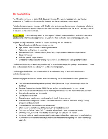
RMEP metal ¾” frameWith Concealed Door OperatorManual SwingInside HoistwayTop down viewOutside HoistwayRMEP ¾” Metal Door Frame, see rough opening chart for R.O. and common sizes.RMEP Low Profile Turn HandleDummy handle with ball catch and J-handle pull coveringHidden integrated interlockASME 5.3.7.2 (2016) RMEP ¾” compliant handle solutions prevent the interior handle from protruding into hoistway.6
PRE-PLANNING STEPSLocate a local dealer and plan your elevator together. Please usethe steps below to guide you in the planning process. Manyaspects affect what drive system will best suit your needs: cardimensions (accessibility), car and shaft door systems, ceilingheights, machine room size and location. Please refer to the DriveSystem Overview on page 7, and the hoistway door systems below.Pre-planning considerations1.2.3.4.Determine what pit depth you can provide.Determine what overhead space you can provide.Determine machine room space and location you can provide.Coordinate with your dealer to go over your options, interior finishes, and upgrades.Drive SystemsDriveSystemCapacitySpeedPit DepthMachine RoomCar rdHPRatingSRH 2:1RopedHydraulic950 lbs.40 FPM10” for residential sling.14” for HD slingMachine Roomrequired, preferredadjacent to shaft, canbe up to 40’ remoteWrap Around GateAccordion gate2 Speed Gate3 Speed GateSwing door2 Speed3 Speed230VAC 1Ph 30Amp230VAC (HD) 1 Ph60 Amp3HPHD 5HPRMRWindingDrum950 lbs.40 FPM10” for residential sling.No heavy-duty slingMachine Roomrequired adjacent torail on bottom floorSwing door2 Speed3 Speed230VAC 1Ph 30 Amp3 HPRMD950 lbs.40 FPM10” for residential sling.No heavy-duty slingNo Machine Room -Swing door2 Speed3 Speed230VAC 1Ph 30 Amp3 HPWrap Around GateAccordion gate2 Speed Gate3 Speed GateWrap Around GateAccordion gate2 Speed Gate3 Speed GateHydraulic DriveWinding DrumHydraulic systems utilize a piston toraise and lower the car by filling orreleasing fluid into the oil tightcylinder.Winding Drum systemsutilize cables attached to awinding drum. Each cable israted to support 5 times thefull load.This drive system can accommodateup to 6 stops in 50’ of travel and israted to 950 lbs standard. 1400optional. Machine-Room-lessavailable (see MRL guide)The drum is attached to amodern motor speedcontroller that varies thespeed for smooth starts andstopsThe Hydraulic Drive is one of themost popular choices forhomeowners looking for quality,safety and the quietest ride.Based on the first elevatorsystems that are still in usearound the world.This drive system is availablein top mounted on the rail orfloor mounted in an adjacentmachine room. MachineRoom-Less available (seeMRL Guide)Hydraulic Drive (SRH)Rail Mounted Winding Drum (RMD)7Floor Mounted Winding Drum (RMR)
COMMON SPECIFICATIONSStandard Features Travel: Maximum 50’0” 2 stops standard (up to 6 stops) Minimum distance between floors 12” Speed:40 feet per minute maximum per code Rated Capacity 950lbs (1400lb with variance) Pit depth: 10” minimum. (14” for HD sling) Single opening standard, front and rear or frontand side opening optional. 3-year limited warrantySafety Features Child safe exclusive wrap around gate system UPS battery lowering and door activation incase of power failure Integrated emergency light in COP In car stop switch and alarm Integrated phone in COP Type A instantaneous safeties Pit stop switch Supplied controller and lighting disconnects Slack cable switchControls PLC control board functions with hydro or drum COP (Car Operator Panel) with LED positionIndicator and integrated push button phone Automatic car lighting Lockable floors upgrade available Floor homing: car returns to designated floor,doubles as flood zone protection. Vacation function for hydro elevatorsCar Features Up to 15 square feet 80”, 84” and 96” cabs are standard Custom height cabs available Matching wood handrail Variety of metal handrails Wear resistant sill/track Unfinished plywood floor to accommodate ¾”finished floor Low energy LED recessed lights (2) standard, 4optional, consult factory for available colors RMEP exclusive wrap around gate with solidwood, metal, wire mesh or glass insertsEquipment 230 VAC 60hz controller/motor/pump assembly 120VAC car lighting circuit Modular 8lb/foot T-rail structure Car frame assembly (sling) Maxton EMV-10 Valve, self-adjusts to load(Hydraulic only) Optional Blaine EV-100 valve (hydraulic only) Winding Drum: Rail mount or Remote MachineRoom Code compliant disconnect included: Mountingoptions: high/low, left/right hand Machine Room-less (MRL) versions available forboth hydraulic and winding Drum systemsUpgrade Features Custom car size up to 18 square feet (mayrequire approval from local AJH) Custom glass car upgrade 1” low profile dot LED lamps (6) optional in avariety of finishes Custom lighting optional Flat panel, raised panel, wire mesh, glassoptions for walls Accordion gate options Auto gate operator option Auto door operator option Gate & door optionso RMEP 3 panel 3 speed gate and landingsystemo 2&3 speed commercial gate and landingsystems Key or keypad operated floor lockouts available8
REQUIRED OVERHEADOverhead is the distance from the top landing floor to the ceiling in the hoistway.This room accounts for the cab as well as the equipment on top of the cab and any equipment on the rails(Overhead Winding Drum, Sheaves).Overhead Required for common cab and gate combinations. (Per Code ASME A17.1 - 5.3.1.3)Overhead may vary due to accessories and configurations.Gate StyleGate & Door HeightWrap Around GateAccordion Gate6’ 8”7”8”Two Speed FireRated Victory84.658” X 36"Two Speed Victory78.75" X 35.5"Two Speed Victory94.5" X *(80")(84")*(96")*Required OverheadHydraulic and 121.5"121.5"124.25"121.5"121.5"124.25"Cab Height6'8" (80")7'(84")*Three Speed Victory78.75" X 31.5"8'(96")*6'8" (80")Three Speed Victory78.75" X 35.5"7'(84")*8'(96")**INDICATES THAT A DROP HEADER IS REQUIRED.Drop headerStandard Cab9Required Overheadwith Winding Drum109.5"112"124"123.5"124"117.75"117.75"124"
HOISTWAY ILLUSTRATIONThese drawingsdepict sampleconstruction only. Itis the responsibilityof theinstaller/contractoror engineer to designand specify structuralsupports. Allconstruction to be incompliance with localcodes.IMPACT LOADVaries by systemand construction10
MACHINE ROOM DESIGNS AND CONTROLLER SPACEMachine Room – Hydraulic (SRH)SRH Hydraulic Controller and PumpNOTE: Controller space not shown, location by installation contractor.Winding Drum (RMD)Winding Drum (RMR)11
STEPS TO PLANNING YOUR HOME ELEVATORDrive Systems Overview (Step 1)Rocky Mountain Elevator Products offers you the choice of two configurations for the roped hydraulic and winding drum, (formachine room-less applications refer to MRL Planning Guide) giving you the flexibility to select the best drive system for yourapplication.Standard Roped Hydraulic: (SRH) 2:1 rope hydraulic unit utilizing (2) 3/8” 8x19 wire ropes running over a sheavemounted atop a hydraulic cylinder950 lbs. capacitySmooth Ride Technology using theindustry’s only self-adjusting rideSubmerged motor for quiet operationEmergency battery lowering, (standard)40 FPM travel speed (increased speedrequires a variance)Slack cable safety device230 V 1Phase 30 Amp with neutral andground (4 wires)StandardHydroWinding Drum:Attic access Inverter controlled variable speed winding drum unit utilizing (2) 3/8” 8X19 steel corewire ropes as suspension means950 lbs. capacity standardRMR drum behind the rail (Figure B)Variable speed for a quality rideFloor specific battery descent (optional)40 FPM travel speed230V 1 Phase 30 Amp with neutral andground (4 wires)Slack cable safety deviceRMD –Rail Mounted Drum (requires atticaccess) (Figure A)Figure ARMDFigure BRMR12
Standard Car Layouts (Step 2)Inline OpeningRail LeftRail RightAdjacent openingRail RearRail LeftOpposite openingRail RightRail Left/RightGate Styles (Step 3)Wrap Around GateAccordion Gate2 Speed Gate3 Speed GateHoistway/Entrance Doors (Step 4)Car Sizes (Common Sizes Shown) (Step 5)18 Sq. Ft. requires localvariance- not A17.1 part 5compliant, 14” pit required.13
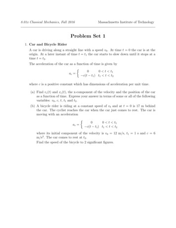
HOISTWAY LAYOUTS (STEP 6)14
15
16
17
18
19
20
21
WORK BY OTHERSDelivery1.Provide smooth (roll-able) access as close as possible to the installation area.Hoistway1.Hoistway wall must be framed on each level as per site-specific equipment shop drawings, not architectural drawings. (All dimensions areto finished wall)2.Hoistway must be plumb and square within ¼”.3.Hoistway doors must be installed on all floors/landings as per site-specific shop drawings.4.Casing trim inside hoistway cannot protrude more than 1/4” from wall.5.Drywall and taping must be complete by time of install.6.No other pipes, wires, liquids, gases, etc. are allowed in hoistway by code.7.Hoistway temperature must be maintained within 60 to 100 degrees Fahrenheit.8.Contractor will furnish appropriate rail backing for T-Rail.9.Rail backing wall must be a load-bearing wall.10. Consult Dealer for span greater than 10’ between floor joists.11. Maintain below 1/8” tolerances throughout hoistway.12. The structure of the hoistway must allow for installation of a chain hoist to transfer materials to the upper landings during elevatorinstallation (Eye bolt of 1,000 lb. capacity).13. 8’0” minimum hoistway overhead above the finished floor at the top landings required for 7’0” car with remote controller.14. Provide an access hatch for servicing the controller/drive unit.Doors1.2.3.4.5.Doorways must be framed with 2x4 construction for proper clearances by codes (reference shop drawings and/or hoistway door detail).Doors must be a solid core (or equivalent) 20-minute minimum fire rating unless serving a garage, then a 1-hour fire rating is required.The doors, hardware, and closers (spring loaded hinges) should be supplied and installed prior to installation.When closed, the landing doors/jambs must leave only 3” of threshold space from inside of hoistway to the backside of the door to allowproper spacing for the hoistway door interlocks, and to meet code (reference shop drawings and/or hoistway door detail).Door openings must be laid out and framed per elevator shop drawings, not architectural drawings.1.2.3.4.Pit must be poured to proper depth and size (reference shop drawings).A clean, dry pit must be maintained.Pit depth must be a minimum of 10” for the standard sling and 14” for HD sling, below the finished floor of the lowest landing.Construction of pit floor must withstand an impact load specified by the configuration of the system.PitMachine Room/Equipment Room1. Elevator Equipment must be within 40’ of hoistway.2. Must have a minimum of 3’0” clear area in front of controller as per electrical code.3. Permanent telephone line to controller. Telephone must be live before inspection.4. Machine room temperature must be maintained within 60-100 degrees Fahrenheit.5. 230V 30Amp Single Phase service whip needs to be ran to Controller.6. 120V 15Amp Single Phase dedicated car light service whip needs to be ran to Controller.Cab and Finish1.All cab choices and any materials being supplied for finishes of this elevator must be provided a minimum of 10 weeks prior to theinstallation of the elevator.Safety1.Hoistway doors or OSHA approved removable barricades must be installed and secured.Storage1.A dry, clean and secure area needs to be provided for the elevator equipment not installed at time of delivery.Acceptance/Final Inspection1.The elevator phone with dial tone must be present prior to inspection.2.Cab interior, door hardware, door trim and door finishes must be complete prior to inspection.3.The elevator cannot be turned over and/or used for construction until it has passed final inspection.22
NOTES:23
TRANSEND SERIES GLASSELEVATORS FOR THE DISTINCTIVE HOMECUSTOM CAB DESIGN 3D CONCEPTS AND MOREFrom concept to creation:RMEP elevator designs are a mixture of code compliance and your imagination. From home design to custom themes we canbuild it. Wood, metal, glass, wire mesh designs that are not only good looking but safe and reliable.Common themes include wood and glass, metal and glass, industrial metal, mine shaft theme with wire mesh, Victorian raised andrecessed panels, and many more. Check out our website and online brochures or visit a dealer today!3D CAD RenderingConceptReality!RMEP uses CAD softwaree to help you bring your imagination to reality. Computer-aidedComputerDesign ensures a perfect fit tothe numbers provided, safe solid construction and desired design.design‘’24
the hoistway face of the landing door or gate and the car door or gate shall not exceed ¾" (0.75 Inches). The distance between the hoistway face of the landing door or gate and the car door or gate shall not exceed 4" (inches). For rough opening size, add 3.5" over the HEIGHT of the door size, 6.75" over the WIDTH of the door size.