Transcription
AIAA 2000-1771Contributions of the Langley TransonicDynamics Tunnel to Rotorcraft Technologyand DevelopmentWilliam T. Yeager, Jr.Vehicle Technology DirectorateU.S. Army Research LaboratoryNASA Langley Research CenterHampton, VA 23681andRaymond G. KvaternikNASA Langley Research CenterHampton, VA 23681AIAA Dynamics Specialists ConferenceApril 5-6, 2000Atlanta, GAFor permission to copy or republish, contact the American Institute of Aeronautics and Astronautics1801 Alexander Bell Drive, Suite 500, Reston, VA 20191-4344
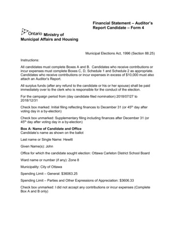
AIAA-2000-1771CONTRIBUTIONS OF THE LANGLEY TRANSONIC DYNAMICS TUNNELTO ROTORCRAFT TECHNOLOGY AND DEVELOPMENTWilliam T. Yeager, Jr.*Vehicle Technology DirectorateU.S. Army Research LaboratoryNASA-Langley Research CenterHampton, VA 23681AbstractA historical account of the contributions of theLangley Transonic Dynamics Tunnel (TDT) torotorcraft technology and development since thetunnel's inception in 1960 is presented. The paperbegins with a summary of the major characteristics ofthe TDT and a description of the unique capabilityoffered by the TDT for testing aeroelastic models byvirtue of its heavy gas test medium. This is followed bysome remarks on the role played by scale models in thedesign and development of rotorcraft vehicles and areview of the basic scaling relationships important fordesigning and building dynamic aeroelastic models ofrotorcraft vehicles for testing in the TDT.Chronological accounts of helicopter and tiltrotorresearch conducted in the TDT are then described inseparate sections.The discussions include adescription of the various models employed, thespecific objectives of the tests, and illustrative results.IntroductionThe Langley Transonic Dynamics Tunnel (TDT)(fig. 1) and the Aeroelasticity Branch (AB) with whichit is associated have a long and substantive history ofaeroelastic research which has made creditable contributions to rotorcraft technology and development.That research, extending from shortly after the tunnel'sinception in 1960 to the present, has included a widerange of experimental investigations using a variety ofscale models and testbeds, and the development andapplication of essential analyses. The results of that*Senior Research Engineer.†Senior Research Engineer, Associate Fellow AIAA.Copyright 2000 by the American Institute of Aeronautics and Astronautics, Inc. No copyright is assertedin the United States under Title 17, U.S. Code. TheU.S. Government has a royalty-free license under thecopyright claimed herein for Government Purposes.All other rights are reserved by the copyright owner.Raymond G. Kvaternik†Aeroelasticity BranchNASA-Langley Research CenterHampton, VA 23681research have contributed substantially to the technology base needed by the industry for designing andbuilding advanced rotorcraft systems. In particular, thework has contributed to supporting rotorcraft researchand development programs, to the fundamental understanding of phenomena involved, and to resolvinganomalies. For convenience of discussion, the rotorcraft investigations may be divided into two categories:helicopters and tiltrotors.Helicopter model testing has been conducted in theTDT since 1963, and has generally taken the form ofresearch testing rather than testing in direct support ofany specific helicopter development program. Severaltestbeds have been used for helicopter testing in theTDT (fig. 2). The first (fig. 2a) was built by LockheedAircraft Company and was used for testing of hingelessrotor configurations in support of the XH-51 researchhelicopter development program. A testbed developedby Bell Helicopter Company was used for two-bladedteetering rotor studies (fig. 2b). The Lockheed testbedwas later refurbished in-house at Langley and becameknown as the Generalized Rotor Aeroelastic Model, orGRAM (fig. 2c). This testbed was used for helicopterrotor testing at the TDT until the late 1970s. The current testbed, known as the Aeroelastic Rotor Experimental System, or ARES (fig. 2d), has been used for allhelicopter rotor testing in the TDT since 1977. TheARES testbed has been used for investigations involving rotor performance, loads, stability, and acousticsfor a number of rotor models. For example, the AREShas been used for the study of conformable rotors todefine their potential for altering blade spanwise andazimuthal airload distributions to improve rotor performance and reduce loads. An active control conceptknown as Higher Harmonic Control (HHC) was testedon the ARES to confirm predictions as to the level ofreduction in fixed-system vibration and blade-vortexinteraction noise. The ARES testbed has also beenused to obtain aeromechanical stability and loads datafor hingeless and bearingless rotor models and to validate existing analytical models. The ARES testbed has1American Institute of Aeronautics and Astronautics
also been used for studies to evaluate rotors incorporating advanced technologies that will be needed tomeet military requirements for increased mission effectiveness and improved safety and survivability infuture helicopters.Tiltrotor aeroelastic research in the TDT (fig. 3) hasbeen about equally divided between supporting research and development programs. This work has itsroots in propeller whirl flutter studies conducted in theTDT in the early 1960s, and some later fundamentalstudies into the whirl flutter behavior of propellershaving flapping blades. Tiltrotor aeroelastic studiesbegan in 1968 in an exploratory parametric investigation of stability, dynamics, and loads using a model ofa proposed Bell Helicopter Company tiltrotor designdesignated the Model 266. In the early 1970s, aerodynamic and flutter clearance tests were conducted insupport of the development program that led to theNASA/Army XV-15 tiltrotor research aircraft. Duringthis same period, a parametric investigation of proprotor whirl flutter was conducted using an off-design research configuration of a proposed Grumman tiltrotordesign. There was a hiatus in tiltrotor research activityat AB from 1974 until 1984, after which tests wereconducted on a Bell tiltrotor model in support of the V22 development program. A second hiatus in tiltrotorresearch occurred from 1985 to 1994, after which therewas a resurgence of tiltrotor activity within AB/TDT,primarily in anticipation of NASA’s Short Haul CivilTiltrotor program. This led to a new tiltrotor researchprogram using a refurbished version of the V-22 modelthat was tested earlier in the TDT in support of the V22 program. The refurbished model has been incorporated into a tiltrotor research testbed called the Wingand Rotor Aeroelastic Testing System (WRATS). Incollaboration with Bell Helicopter Textron, studies under the current research program are focusing on arange of aeroelastic technical areas that have beenidentified as having the potential for enhancing thecommercial viability of tiltrotor aircraft. In particular,emphasis is being placed on the development of activeand passive techniques for vibration control, stabilityaugmentation, and increased aerodynamic performanceof tiltrotor aircraft.Several overviews of TDT aeroelastic research activities have been published over the years (see, for example, refs. 1-9). However, these reviews have eitherbeen generic discussions of work conducted in theTDT without any particular emphasis on rotorcraft, orspecific to rotorcraft but incomplete with respect to thescope of the work reviewed. The purpose of this paperis to present a complete and unified historical accountof AB/TDT aeroelastic research accomplishments thathave contributed to rotorcraft technology and devel-opment since the inception of the TDT in 1960. Relevant ancillary studies contributing to this technologybase are also included. The paper begins with a summary of the major characteristics of the TDT and a description of the unique capability offered by the TDTfor testing aeroelastic models by virtue of its heavy gastest medium. This is followed by some remarks on theuse of scale models in the design and development ofrotorcraft vehicles, and a review of the basic scalingrelationships important for designing and building dynamic aeroelastic rotorcraft models for testing in theTDT. Helicopter and tiltrotor tests that have been conducted in the TDT are then described in separate sections. In each of these sections, a chronological account of the pertinent work and contributions is given.These discussions include a statement on the objectivesof the tests, a photograph and a description of the various models and testbeds used, and illustrative resultsthat characterize the phenomenon (or phenomena) under investigation. Where and when appropriate, an explanation of the pertinent fundamental mechanisms andinteractions involved in the phenomena is included inthe discussion. Each section concludes with a résuméof current and planned research activities.Tunnel CharacteristicsThe Langley Transonic Dynamics Tunnel (TDT) isa single-return, closed-loop, continuous-flow, variablepressure, slotted-throat wind tunnel having a test section 16-feet square (with cropped corners). An aerialview of the wind tunnel and its adjoining engineeringand equipment building is shown in figure 1. A schematic depicting the general arrangement of the tunnelis shown in figure 4. The tunnel uses either air or aheavy gas as the test medium and can operate at total(stagnation) pressures from near vacuum to atmospheric. It has a Mach number range from near zero toabout 1.2, with attendant maximum Reynolds numbersof about three million per foot in air to about ten million per foot in heavy gas. Both Mach number andpressure are independently controllable.The TDT is specially configured for aeroelastictesting. Large windows are provided for close, unobstructed viewing of the model from the control room.A set of four by-pass valves is present in the windtunnel circuit to allow quick reduction in the dynamicpressure in the test section in case of model instability.The tunnel fan blades are protected from debris ofdamaged models by a wire-mesh safety screen. A variety of model mount systems is available. For helicopter testing, stand-mounted testbeds have been used.For tiltrotor testing, stand-mounted, sidewall-mounted,sting-mounted, and rod-mounted models have been2American Institute of Aeronautics and Astronautics
used. The TDT also offers an airstream oscillator system for gust studies. The system consists of an arrangement of biplane vanes located on either side ofthe tunnel entrance section (fig. 5). Vane frequency andamplitude are adjustable and the two pairs of vanesmay be operated either in phase or out of phase to provide vertical or rolling gust fields.The tunnel was originally constructed as a 19-footdiameter subsonic pressure tunnel in 1938 (ref. 10). Inthe late 1950s, the facility was converted to a transonicdynamics tunnel to fill the need for a wind tunnel dedicated to the testing of large aeroelastic models of aerospace flight vehicles from low subsonic through transonic speeds. This new aeroelastic testing capabilitywas made possible by using the high-molecular-weightgas R-12 as the test medium (ref. 11). A number ofsubsequent comparative tests (see, for example, refs.12-15) confirmed pre-conversion studies as to thesoundness of testing aeroelastic models in R-12 insteadof air. Environmental concerns raised in the late-1980sregarding the continued widespread use of R-12 led toa NASA decision to replace the R-12 used in the TDTwith the environmentally acceptable and essentiallyequivalent refrigerant R-134a. Conversion of the TDTheavy gas test medium from R-12 to R-134a was completed in 1997 and is described in references 16-17.Subsequent wind tunnel characterization and calibration tests were completed in 1998, after which normaltunnel operations resumed. Because R-12 and R-134ahave comparable properties, the primary flow characteristics of the TDT for R-134a operations are notmuch different from those for R-12, as was expected.For this reason, the advantages of testing in heavy gaswill continue with R-134a. However, because thespeed of sound in R-134a is slightly higher than in R12 rotorcraft models tested in R-134a must be operatedat higher rotor rotational speeds to maintain Machscaling.Since its inception, the TDT has been a unique national facility for testing aeroelastic models of a varietyof aircraft, spacecraft, and launch vehicles (see, for example, refs. 1-2). The heavy gas feature of the tunnel(in combination with its large size) offers several advantages over air with respect to designing, building,and testing aeroelastic models. For example, improvedmodel-to-full scale similitude, eased fabrication requirements, lower model vibration frequencies, reduced test section flow velocities, larger test Reynoldsnumbers, and reduced tunnel power requirements. Thesize of the test section easily accommodates model rotors up to 10 feet in diameter. More detailed descriptions of the TDT and its capabilities may be found inreferences 16-17.Some Remarks on the Use of Scale ModelsAeroelastically-scaled wind-tunnel models haveplayed an important role in the design, development,and verification process in diverse fields of engineering, including aerospace engineering (see, for example,refs. 18-23). Their use is particularly prolific in thefield of aeronautics wherein dynamic aeroelastic (i.e.,flutter) models are extensively employed both to substantiate that an aircraft design is free of aeroelastic instabilities within its flight envelope, and to validateanalyses. Analytical capabilities for addressing aeroelastic design issues of aircraft have improved significantly over the years. However, because aircraft havecontinued to increase in structural and aerodynamiccomplexity, the need to rely on wind-tunnel tests ofsub-scale models to verify predicted behavior and performance before entering the flight test stage of a development program remains. Such models are alsowidely used in research investigations dealing withsuch issues as active control of aeroelastic stability andresponse, buffet load alleviation, and for the validationof analytical and computational methods used in design.The importance of sub-scale models for helicopterresearch has been recognized as early as 1950 (refs. 2425). However, sub-scale models have also played avaluable, although perhaps less prominent, role in thedesign and development of helicopters, tiltrotors, andV/STOL aircraft (for example, see refs. 22-23, 26-27).The importance and role of sub-scale models in rotorcraft research and development have been recognizedby both government and industry on many occasions.For example, references 28-29 emphasized the importance of a properly conducted wind-tunnel test programthat includes both model-scale and full-scale testing toreduce the technical risk of a rotorcraft developmentprogram, and to lessen the chance for surprises in theflight test stage.Model Scaling ConsiderationsDynamic aeroelastic models may be classified intotwo general groups: (1) research models, and (2) prediction models. Research models do not represent anyparticular aircraft and are at most only broadly representative of full-scale designs. They are used primarilyto gain insight into aeroelastic problems (e.g., identifythe types of flutter which may be associated with a newor unusual configuration), to provide experimental datafor comparison with analysis, and to provide generaldesign information on flutter trends that occur withvariations in system parameters. Prediction models arebased on actual full-scale designs and are intended to3American Institute of Aeronautics and Astronautics
predict the full-scale behavior of specific aircraft.These models are related to the full-scale designs thatthey represent by certain scaling relationships. Itshould be noted that prediction models can also be usedeffectively as research models.A model will exhibit similitude or similarity to afull-scale structure provided certain dimensionless ratios have the same values for both. These dimensionless ratios may be determined by dimensional analysisof all the quantities involved in the problem or (if thestructure is simple enough) from the differential equations which define the system. The objective of thetheory of similitude (refs. 18, 19, 30-32) is to establishthose relationships that must be maintained to permitreliable predictions to be made from measured modelbehavior. Usually, not all dimensionless ratios can bemaintained at full-scale values with reasonable choicesof materials and scale factors in available test facilities.In such cases, complete similarity cannot be maintained and compromises must be made, based on experience and knowledge of the problem, by which theless important dimensionless ratios are allowed to deviate from full-scale values. Fortunately, a model isusually designed to study only a particular phenomenon (or class of phenomena), in which case only thosedimensionless ratios important for the phenomena ofinterest need be maintained at their full-scale values.The requirements for achieving dynamic and aeroelastic similitude of model and full-scale aircraft andhelicopters are replete in the literature (see, for example, refs. 31-36) and will be reviewed here only brieflyas they apply to rotorcraft. As mentioned above, thesimilarity requirements can be obtained either by applying dimensional analysis to the problem or by examining the appropriate governing equations written innondimensional form. Application of such proceduresresults in the identification of the basic independentnondimensional parameters that must have a one-toone correspondence between model and full scale toensure adequate representation. For the study of dynamic aeroelasticity and unsteady aerodynamics phenomena, five basic similarity parameters are indicated:Mach number, advance ratio (reduced frequency),Lock number (mass ratio), Reynolds number, andFroude number. The other dependent ratios relatingmodel quantities to full-scale quantities can be derivedfrom these basic similarity parameters. The modelsmust also be geometrically similar to their full-scaleequivalents in external shape as well as in their distribution of mass and stiffness. In addition, any important body degrees-of-freedom must be included in themodels.The simultaneous satisfaction of the five similarityparameters noted above is not possible because of conflicting requirements which result for the design of amodel. In conventional wind tunnels using atmospheric pressure air as the test medium, only three of thefive parameters can be maintained at their full-scalevalues. For the simulation of flight conditions wherecompressibility effects are important, it is well established that the full-scale values of Mach number, advance ratio, and Lock number must be maintained inthe model. This is true whether the model is to betested in air or heavy gas. However, if the model is designed for testing in heavy gas, Froude number may bemaintained simultaneously with Mach number, advance ratio, and Lock number by selecting an appropriate length scale factor (about .20 to .29 depending onthe simulated full-scale altitude). For simulation offlight conditions where compressibility effects are notimportant models are usually designed to maintain fullscale values of advance ratio, Froude number, andLock number when tested in air. However, for suitablelength scale factors, these models can simultaneouslyobtain near full-scale values of Mach number whentested in heavy gas. It is generally not possible tosimulate full-scale Reynolds number in either the air orheavy gas test mediums of the TDT. However, the useof heavy gas permits a nearly three-fold increase inReynolds number over comparable conditions in air.Some of the more important aeroelastic scale factors applicable to rotorcraft models in the TDT aresummarized in table 1. Scale factors are tabulated fortesting in air, R-12, and R-134a for the cases in whicheither Mach or Froude number is maintained at its fullscale value in addition to Lock number and advanceratio.Helicopter Research ContributionsTests Utilizing the Lockheed Aircraft Testbed1963 - 1964The initial model helicopter tests in the TDT wereconducted in 1963 and 1964 as part of a cooperative effort between the U. S. Army, Lockheed Aircraft, andNASA to conduct hingeless rotor research investigations (refs. 37-40). The tests were conducted using a1/3-size hingeless rotor model that was 10 feet in diameter (fig. 2a). The model blades were ballasted toallow testing in R-12 at a density of 0.008 slugs/ft3. Anumber of configurations were tested resulting in research information that included structural loads andaerodynamic data for all the configurations tested. The1963 and 1964 tests included rotor configurations with4American Institute of Aeronautics and Astronautics
three, four, and six blades as well as variations in theblade flapwise and chordwise stiffnesses and stiffnessdistributions. Each configuration was tested through aforward speed and load factor range simulating conventional helicopter and compound helicopter operation (refs. 37-38).The 1963 test involved only a three-bladed hingeless rotor configuration with matched root stiffness.Testing was conducted at simulated forward speedsfrom 60 to 240 mph over a range of rotor load factorsat advancing tip Mach numbers up to 0.91. Data wereobtained for helicopter, unloaded rotor, and compoundhelicopter modes of operation and indicated a beneficial influence of blade twist on chordwise cyclic loadsin forward flight. This rotor was designed to enablewide variations in dynamic characteristics and therefore was not representative of an optimized design.The test in 1964 was conducted using a blade and rotorhub design that was optimized for low drag. The bladeflapwise and chordwise stiffnesses were also approximately matched along the blade span. This test involved three-, four-, and six- bladed rotors with thefour-bladed configuration considered as the baseline.As in the 1963 test, all configurations were tested overa range of forward speeds and rotor load factors to obtain structural loads and performance data. Results indicated that the optimized rotor design with lowchordwise stiffness blades showed considerable promise from the standpoint of structural loads, vibration,and performance. The results of these two hingelessrotor tests were encouraging with regard to the use ofhingeless rotor configurations and were of use in thedevelopment of the Lockheed XH-51 helicopter.Tests Utilizing Bell Helicopter Company TestbedIn the late 1960s and into the 1970s, the emphasisin helicopter testing at the TDT was on two-bladedteetering rotor configurations. The tests conducted inthis timeframe used 1/4- and 1/5- size teetering rotormodels mounted on the testbed developed by BellHelicopter Company (fig. 2b).1969In 1969, a teetering rotor test (ref. 13) was conducted to obtain data to assess three areas of interest: 1)the aerodynamic characteristics of rotors operating atcombinations of high advance ratio and high advancingtip Mach number; 2) the feasibility of obtaining rotorstructural and aerodynamic loads from a dynamicallysimilar scaled model; and 3) the validity of data obtained in an R-12 atmosphere. This test used a 1/4size, geometrically and dynamically scaled rotor system representative of those used on Bell HelicopterCompany UH-1C and AH-1G aircraft. An additional1/4-size model rotor was used that had different twistand airfoil characteristics than the scaled rotor system.Assessment of the wind-tunnel results was made bycomparing to existing full-scale wind-tunnel data andfull-scale flight data. Comparisons of theoretical calculations with the wind-tunnel data were also made.Results documented in reference 13 show that modeland full-scale experimental rotor performance as afunction of advance ratio showed no significant trenddifferences. Comparisons of model and full-scale rotorperformance showed good agreement with variations inadvancing tip Mach number. Calculated rotor performance trends with advance ratio and with advancing tipMach number were not found to be in as good agreement with full-scale data as was the wind-tunnel results. Correlation of model and full-scale blade oscillatory loads did not yield the accuracy desired. It wasconcluded that non-scaled rotor hub impedance anddiscrepancies in the full-scale blade stiffness valuesused to produce the model blades probably caused thislack of agreement. Finally, it was concluded that trendcorrelations showed that full-scale loads could be determined in an R-12 atmosphere using a properlyscaled rotor model.1973References 15 and 41 document results of a teetering rotor test conducted in 1973 using the same testbedas the 1969 test. This test continued the evaluation ofR-12 as a suitable test medium for model helicopterrotors (ref. 15), and investigated the effects of hub inplane support parameters ("hub impedance") on thechordwise oscillatory loads of a two-bladed teeteringrotor (ref. 41). To evaluate the suitability of R-12 as atest medium, the studies involved testing a 1/5-sizeaeroelastically scaled helicopter rotor in R-12 at thesame advance ratios, tip Mach numbers, shaft angles ofattack, and collective pitch values as a full-size helicopter rotor tested in air. Reynolds number variationswere achieved through controlled R-12 density changesand the use of a wide chord model rotor that was notaeroelastically scaled. Integrated rotor performancefrom the aeroelastically scaled model rotor provideddata trends and magnitudes that agreed well with fullscale rotor data (figs. 6-7) even at the lower values ofmodel Reynolds numbers. An exact match of full-scalerotor Reynolds number was accomplished by utilizingthe wide chord model rotor, but with accompanyingmismatches in rotor solidity and aeroelastic scaling.Performance results obtained for the full-scale andmodel-scale rotors are summarized in figure 8. RegionB of figure 8 illustrates the expected performance trendwith decreasing Reynolds number for the wide chordblade, i.e., more torque required at a given rotor liftingtask. An unexpected result of these tests is illustrated5American Institute of Aeronautics and Astronautics
by Region A of figure 8 which shows that better modelperformance correlation with full-scale values wasachieved with a dynamically scaled rotor of the correctsolidity than with a rotor that matched Reynolds number but, was not dynamically scaled. It was concludedthat Reynolds number effects may be minor in rotoraerodynamic performance testing in comparison to thecombined effects of rotor solidity and blade elasticproperties.The determination of the effect of hub inplane support parameters on two-bladed teetering rotor chordwise oscillatory loads consisted of : 1) a shake test todefine the impedance of several testbed configurationsas a function of frequency, and 2) testing of the configurations in the TDT. Wind-tunnel test resultsshowed that the one-per-rev inplane bending momentscould be changed by a factor of two, depending on thetestbed configuration, at the same aerodynamic operating condition. The higher harmonic blade loads andpitch link loads were not affected by changes in inplanehub impedance. Additionally, the test results generallysubstantiated the predicted trends, although differencesin the magnitude of the blade bending moments wereobserved when compared to predicted results. Some ofthese differences were attributed to the influence of thetestbed strain-gage balance or tunnel floor on hub impedance. A definitive reason for the difference betweenthe measured and calculated blade bending momentswas not arrived at since neither of these effects wereaccounted for in the analysis.Tests Utilizing the GRAM TestbedIn 1974 and 1975 teetering rotor tests were conducted utilizing the GRAM testbed (fig. 2c). Theseteetering rotor tests (ref. 6) involved a 1/4-size aeroelastically scaled model of a Bell Helicopter CompanyAH-1G "Cobra" rotor (fig. 9), and two 1/5-size aeroelastically scaled wide-chord rotor configurations, with(fig. 10) and without a mid-span flap hinge (fig. 11).1974The purpose of the AH-1G rotor test (ref. 6) was todetermine whether two-bladed teetering rotors can experience stall flutter, which is a factor that limits theforward flight speed of articulated rotor configurations.Stall flutter is a phenomenon that is characterized byhigh oscillatory blade loads at the first torsional frequency of the blade occurring on the retreating side ofthe rotor disk. Blade loads and rotor performance datawere obtained for the AH-1G model rotor up to advance ratios of 0.40. In order to compare the modeltest conditions with the full-scale aircraft flight envelope, model thrust values for selected test points wereconverted to full-scale load factors. These results wereplotted on the aircraft flight envelope as shown in figure 12. Based on the comparison with the full-scaleload factors in figure 12 it was determined that modeldata were obtained that corresponded to full-scalethrust values both within and without the aircraft sustained operating envelope. Model thrust data were alsoobtained outside the sustained operating value of theaircraft, but within the maneuver, or transient, envelope. It should be noted that the model tests did notsimulate maneuvers, but rather the model thrust simulated the full-scale thrust required in maneuveringflight. For three of the test points presented in figure12, the model blade torsional moment waveforms at45% blade radius are shown for two rotor revolutions.Note that at an advance ratio of 0.2, the torsional waveform at a low thrust condition does not indicate any oscillations on the retreating side of the disk (180 deg. to360 deg. azimuth) that could be attributable to stallflutter. However, for the higher thrust condition at anadvance ratio of 0.2 there are signi
The Langley Transonic Dynamics Tunnel (TDT) (fig. 1) and the Aeroelasticity Branch (AB) with which it is associated have a long and substantive history of aeroelastic research which has made creditable contri-butions to rotorcraft technology and development. That research, extending from shortly after the tunnel's