Transcription
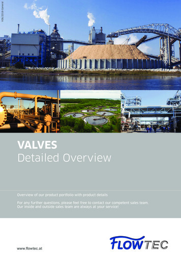
Instrument Valves & ManifoldsWAY MANIFOLDSInstrument valves & manifolds
OVERVIEW2ASTAVA offers a broad lineASTAVA draws from a strong engineering heritage, as well as seasoned businessmanagement. We offer a broad range of products – valves and manifolds suitablefor gas and liquid services-as well as full-service solutions that include customengineering, design and manufacture of Instrument enclosures, modular mountingsystems, hook-ups and interlocking solutions for critical conditions and temperatures.of 1,2,3,4 and 5 instrumentmanifolds-all available in a widerange of materials and fullycompatible with the requirementsof the Oil & Gas, Petro-Chemicaland Chemical industries.In addition to this standard rangeof products, ASTAVA has over3,500 different types of valves andmanifolds available.As a customer-focused company, ASTAVA provides high-quality products andengineering solutions that address our customers’ business and technicalrequirements.For the ASTAVA line, we can offer scalability to design:Choice of materials from AISI 316(L) to special alloy solutions for highly toxic areasConnections, pressure and temperature ratings varietiesBonnet assemblies offer different stem, seal and material selectionsOption for standard packing, O-Ring sealing and fugitive emissions bonnetsExtensive range of valve configurations and flow schemesFully equipped instrument enclosuresWith over 50 years of designing and manufacturing reliable products and solutions,ASTAVA has acquired an outstanding reputation for quality and customer service. Weare always inspired by the need to evolve and stay ahead of theever-changing marketplace.INDEXIntroduction02Manifold features and benefit03Bonnet and stem concept04Materials of construction051-Way Manifold06Ordering information for 1-Way082-Way Manifolds09Ordering information for 2-Way113-Way Manifold12Ordering information for 3-Way154-Way Manifold16Ordering information for 4-Way175-Way Manifold18Ordering information for 5-Way21Accessories22Astava product range25
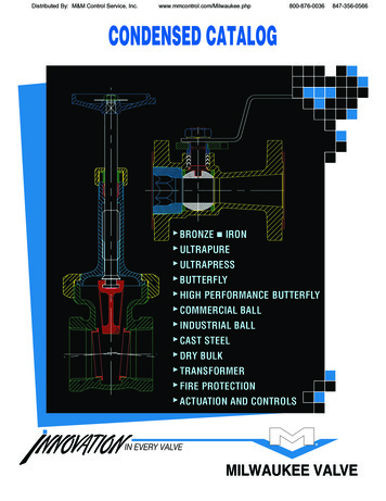
MANIFOLD FEATURES AND BENEFITSNACE MR-01-75 / MR-01-03CERAMIC STEM BALL TIP Al2O3All manifolds comply withNACE MR-01-75 / MR-01-03 standards.Superior hardness prevents deformationof the sealing tip and wear, significantlyincreasing the lifetime of the product forisolation purposes.FULL TRACEABILITYBONNET SELECTIONSO-ring stem-seal bonnet1. No packing adjustment2. Extremely low operating torque3. Compact design4. Long life-cycle5. Sealing below stem thread6. Metal-to-metal bonnet optionPacking stem-seal bonnetAll products are fully traceable to theircomponents.1. Wide chemical compatibility range2. High temperature option (Grafoil )3. Low operating torque4. Sealing below stem threadWIDE VARIETY OF SEALINGMATERIALSPTFE; Grafoil ; Fluorocarbon FKM; NBR;EPDM; Silicon; and perfluorelastomerproviding a wide coverage of applications.STEM MATERIALST. ST. 316 Ti with chromiumcarbide diffusion coating1. Long life-cycle2. Galling preventionFeaturesCertified for ISO 15848-1:2006(E), (With PEEK or Polyimide seals)Blowout-proof stemIntegrated back seat on stem for a secondary seal in the fully opened positionSafety stop pin – prevents the bonnet from detaching the body due to vibrationStem seals below stem threadsA choice of O-ring materialsOxygen clean per ASTM G-93 as an option100% Factory Tested Compliance with MSS–SP–99Direct mount flange design per IEC61518 (MAWP 6000 psig)Working pressure range up to 690 bar (10,000 psig)Working Temperature range up to 550 C (1022 F)Grafoil —TM GrafTech International Holdings, Inc.INSTRUMENT VALVES & MANIFOLDS3TECHNICAL DATAThe following unique features of the Astava line of instrument manifolds enable tailoring ourhigh-quality products to the exact requirement of the customer and application:
Astava valve bonnets have color coded ring labels forservice identification:The chemical composition of a ceramic ball tip is superior inhardness and functionality to a metal ball tip, eliminating sealingtip deformation and significantly increasing the lifetime of theproduct.The stem threads are rolled and an integrated back seatdesign is applied to the packing type of bonnet.Applying a Stainless Steel 316 Ti stem with a chromium carbidediffusion coating results in maximum operation cycles andminimal risk of stem galling. Both packing and O-ringbonnets are designed with sealing below stem threads formaximum protection of the stem threads.For maximum safety, the bonnet design prevents stem blowout,and a locking pin prevents unintentional disassembling of thebonnet.Red:Blue:Green:Vent ValvesIsolate ValvesEqualize ValvesFor severe service applications, ASTAVA manifolds can beconfigured with a metal-to-metal seal below the bonnetthread. A dust ring is attached to the bonnet thread or tackweld on the locking pin for extreme vibrating conditions.Anti-tamper*PRESSURE AND TEMPERATURE RATINGT-barTemperature ( F)0130Locking device230 330 430 530 630 730 830 932 1030 1130 essure (Psig)Pressure (bar)4The special sealing design applied in allASTAVA Instrument Manifolds features a nonrotating ceramic ball erature ( C)PackingMaterialGrafoil Down to -60 C (-76 F)PTFEDown to -60 C (-76 F)PEEKDown to -60 C (-76 F)PolyimideDown to -10 C (14 F)O-Ring Fluorocarbon FKMMaterialDown to -20 C (-4 F)NBRDown to -34 C (-29 F)PerfluorDown to -40 C (-40 F)EPDMDown to -45 C (-49 F)10,000 psi (690 bar)Grafoil —TM GrafTech International Holdings, Inc.Available upon requestHANDLE OPTIONSThe standard handle of the ASTAVA line of instrument manifoldsis a Stainless Steel T-bar. For high pressure applications of10,000 psi (690 bar). an extended T-bar or handwheel can be applied. Anti-tamper bonnet and key* lock optionsassure that the manifold is operated by qualified personnel only.*Not included in order of anti-tamper bonnet manifold. This key should beseparately ordered.CLEANINGAll ASTAVA instrument manifolds are cleaned in accordancewith the ASTAVA cleaning procedure. Oxygen clean is availablein accordance with ASTM G-93.TESTINGAll ASTAVA instrument manifolds are factory tested withNitrogen at 800 psig (55 bar) based on MSS-SP-99. Seats have amaximum allowable leak rate of 0.1 std cm3/min.The Hydrostatic and Helium leak tests are available uponrequest.
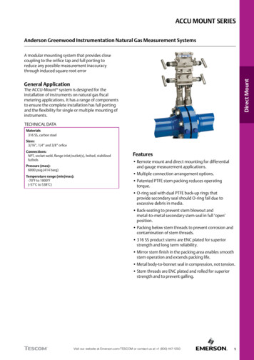
MATERIAL OF CONSTRUCTION23221471715A106APacking Bonnet8786B5B96B5B89O-Ring Bonnet9Metal-to-Metal BonnetBottom metal seal protectsbonnet’s threads from thefluid. For fugitive emmissionsapplicationsPacking BonnetNoPartQty. MaterialO-Ring BonnetQty. MaterialMetal-to-Metal BonnetQty. Material1Set Screw1St.St. 3041St.St. 3041St.St. 3042Bar Handle1St.St. 316L1St.St. 316L1St.St. 316L3Gland1St.St. 316L----4Locking Nut1St.St. 316L----Pressure Ring1St.St. 316L----5A5BBack-up Ring--2Virgin PTFE2Virgin PTFE6AStem Packing1Virgin PTFE----6BStem O-Ring-1Fluorocarbon FKM1Fluorocarbon FKM7Bonnet1St.St. 316L-1St.St. 316L1St.St. 316L8Stem1St.St. 316Ti Chrome-Carbidediffusion coated1St.St. 316Ti Chrome-Carbidediffusion coated1St.St. 316Ti Chrome-Carbidediffusion coated9Ball1Ceramic1Ceramic1Ceramic10Dust Protector----1Fluorocarbon FKMINSTRUMENT VALVES & MANIFOLDSTECHNICAL DATA5
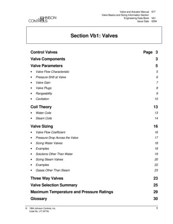
WAY 8102-0170.02.76--32.01.2679.03.1150.0 1.97-104-06110.0 4.3338.01.5032.01.2663.02.4845.0 1.77-104-01110.0 4.3338.01.5032.01.2679.03.1150.0 1.971/2” FNPT-1/2” FNPT1/2” FNPT-1/2” MNPT1/2” FNPT(3x)1/2” MNPT1/2” FNPT(3x)NEEDLE VALVE102-06INSTRUMENT1/2 - 14 NPTPROCESS1/2-14 NPTECAMULTIPORT VALVE104-06EPROCESS1/2-14 NPTCBCDin1/2” FNPTD OpenCmmVent / BleedCBinInstrumentD art NumberEnd ConnectionINSTRUMENT1/2 - 14 NPT (x3)6InstrumentMountTypeSTANDARD CONFIGURATION DIMENSIONS1-WAY MANIFOLDSAmmin45.0 1.77
WAY MANIFOLDS1RemoteMountAmmBinmmin184.0 7.2438.01.5032.01.2663.02.4845.0 1.77184.0 7.2438.01.5032.01.2679.03.1150.0 1.97106-06100.0 3.5430.01.1832.01.2663.02.4845.0 1.77106-01100.0 3.5430.01.1832.01.2679.03.1150.0 1.971/2” MNPT1/2” FNPT (3x)-108-061/2” MNPT1/2” FNPT (3x)-108-011/2” MNPT1/2” FNPT1/4” FNPT1/2” MNPT1/2” FNPT1/4” FNPTEXTENDED MULTIPORT VALVE108-06INSTRUMENT1/2-14 NPT (x3)ECBAGAUGE VALVE106-06D OpenPROCESS1/2-14 NPTINSTRUMENT1/2-14 NPTECVENT/TEST1/4-18 NPTCBAINSTRUMENT VALVES & MANIFOLDSEmmVent / BleedCDinInstrumentinCmmProcessD Open7DimensionsASTAVAOrderingPart NumberEnd ConnectionPROCESS1/2-14 NPTmminTECHNICAL DATAInstrumentMountTypeSTANDARD CONFIGURATION DIMENSIONS1-WAY MANIFOLDS
WAY MANIFOLDS1ORDERING INFORMATION1-WAY MANIFOLDSFamily Type-Flow ConnectionOptionConnection01Female toFemale1/4 NPT02Female toFemale1/2 NPT /10K03Male toFemale04Male toFemale0608Warning!Male toFemaleMale toFemale1/2 NPT1/2 NPT1/2 NPT1/2 NPTThe system designer and user have the sole responsibility for selecting productssuitable for their special application requirements, ensuring their safe andtrouble-free installation, operation, and maintenance. Application details,material compatibility and product ratings should all be considered for eachselected product. Improper selection, installation or use of products can causeproperty damage or personal injury.Grafoil —TM GrafTech International Holdings, Inc./B/34OptionsCode1SketchTypeSchematicFlowBody / SealingSelectionSize8HOW TO ORDERPackingAll connectionsBSPP-01PTFESS 316(L)/ ATAnti-TamperBonnets10K Solution-02PTFEAlloy 400/COxygenCleaned3/4” Process &Instrument-03PTFEAlloyC-276/ LDLockingDevice-04PTFETitan-05GrafoilSS 316 (L)-06FluorcarbonFKMSS 316 (L)-09PerfluoroelastomerSS 316 (L)-12PTFEAlloy 625-22PTFEDuplex F51-29PTFESuperDuplex F53-40PTFEAlloy 825-81PTFE321MaterialConnection
trumentVent / Bleedmminmm1/2” FNPT*Flange1/4” FNPT213-0685 3.35--65.0 2.56 182 7.17 32.0 1.26 5.0 0.20inmmin*Flange*Flange1/4” FNPT217-06153 6.02--56.0 2.20 82 3.07 65.0 2.56 20.0 0.79* Flange Standard per IEC 61518-A213-06DINSTRUMENT41,3 (1.63)CISOLATEVENT45,0 (1.77)VENT/PURGE1/4-18 NPTFPROCESS1/2-14 NPTAM8-6H ( 4x )EØ12.0 (X2) (0.47)16,0 (0.63)AINSTRUMENTCFØ 8.2 (Ø 0.32)VENTØ12,0 ( 2x )(Ø0.47)7/16-20 UNF ( 2x )E45,0(1.77)D41,3 (2x)(1.63)PROCESS217-06ISOLATEVENT1/4-18 NPTINSTRUMENT VALVES & MANIFOLDSTECHNICAL DATAInstrumentMountTypeASTAVAOrderingPart NumberEnd ConnectionWAY MANIFOLDS2STANDARD CONFIGURATION DIMENSIONS2-WAY DIRECT MOUNT
ensionsASTAVAOrderingPart NumberEnd ConnectionAmmVent / BleedBinmmCinmmEinmmFinmmin1/2” FNPT1/4” FNPT205-0679 3.11 79.0 3.11 32.0 1.26 92.0 3.62 32 1.26 26 1.021/2” FNPT1/4” FNPT211-06107 4.21 79.4 3.13 65.0 2.56 65.0 2.56 32 1.26 35 1.381/2” FNPT1/2” FNPT1/4” FNPT207-06156 6.14--65.0 2.56 59.0 2.32 32 1.26 18 0.71DAVENTVENT1/4-18 NPTPROCESS1/2-14 NPTINSTRUMENT1/2-14 NPT45.0(1.77)ISOLATEM8-6H ( 2x )CBF211-06DACFISOLATEVENT1/4-18 NPT32,0(1.26)INSTRUMENT1/2-14 NPTNTVEM8-6H ( 2x )45.0 (1.77)PROCESS1/2-14 NPTEB207-06AD32.0 (1.26)INSTRUMENT1/2-14 NPTVENT 1/4-18 NPT45,0 (1.77)M8-6H ( 2x )ISOLATEVENTFECmm1/2” FNPT205-0620,0 (0.79)Din1/2” FNPTE10WAY MANIFOLDS2STANDARD CONFIGURATION DIMENSIONS2-WAY REMOTE MOUNTPROCESS 1/2-14 NPT
HOW TO ORDEROptionTypeConnectionPackingAll connectionBSPP01PTFESS 316(L)/ ATAnti-TamperBonnets10K Solution02PTFEAlloy400/COxygenCleaned/343/4” Process &Instrument03PTFEAlloyC-276/ LDLockingDevice/141/4” proces &instrument04PTFETitan05GrafoilSS 316 (L)06FluorcarbonFKMSS 316 (L)09PerfluoroelastomerSS 316 (L)12PTFEAlloy 62522PTFEDuplex F5129PTFESuperDuplex F5340PTFEAlloy 82581PTFE32103Male toFemale04Female toFemale1/4 NPT /10K05Female toFemale1/2 NPT08Female toMale1/2 NPT071113Female toFemaleFemale toFemaleFemale toFlanged1/2 NPT1/2 NPT1/2 NPTFemale toFlanged1/2 NPT06Male toMale1/2 NPTWarning!/B1/2 NPT17The system designer and user have the sole responsibility for selecting productssuitable for their special application requirements, ensuring their safe andtrouble-free installation, operation, and maintenance. Application details,material compatibility and product ratings should all be considered for eachselected product. Improper selection, installation or use of products can causeproperty damage or personal injury.INSTRUMENT VALVES & MANIFOLDS11OptionsCode2SketchSizeSchematicFlowBody / SealingSelectionMaterialConnectionTECHNICAL DATAFamily Type-Flow ConnectionWAY MANIFOLDS2ORDERING INFORMATION2-WAY MANIFOLDS
InstrumentMountTypeDimensionsASTAVAOrderingPart NumberEnd nProcessInstrumentVent / Bleed1/2” FNPT*Flange-302-06181.0 7.13 95.0 3.74 86.0 3.39 82.0 3.11 66.0 2.60 20.0 0.791/2” FNPT*Flange-306-06161.0 6.34 107.0 4.21 65.0 2.56 150.0 5.91 32.0 1.26 16.0 0.63302-06* Flange Standard per IEC 61518-AAC45.0 (1.77)DPROCESS (2x )1/2-14 NPTEISOLATEISOLATE41.3(2X) (1.63)EQUALIZEB12.0 (X4) 0.47INSTRUMENTF8.2 (0.32)54.0 (2X)2.13306-06A45,0 (1.77)EALIZM8-6H (2x)32,0 (1.26)54,0 (2.13)120,0 (4.72)DPROCESS (2x)1/2-14 NPT12.0 (x4) (0.47)FECINSTRUMENTBEQU41,3 (1.63)12WAY MANIFOLDS3STANDARD CONFIGURATION DIMENSIONS3-WAY DIRECT MOUNT
AmmBinCinmmDinmmEinmmFinmminInstrumentVent / Bleed1/2” FNPT*Flange-329-06210.0 8.27 106.0 4.17 65.0 2.56 115.0 4.53 32.0 1.26 16.0 0.63*Flange*Flange-303-06181.0 7.13 95.0 3.74 86.0 3.39 82.0 3.11 66.0 2.60--* Flange Standard per IEC 61518-A329-06AD"INSTRUMENT"12.0 (4X) 0.47EALIZB"PROCESS" ( 2x )1/2-14 NPTCISOLATE41,3 (2x) (1.63)EQUISOLATE45.0 (1.77)mmProcessM8-6H (2x)32.0 (1.26)54.0 (2.13)EF* Optinal vent / test ports303-06AC54D45 (1.77)ISOLATEE7/16-20 UNF-2B (4x)INSTRUMENT VALVES & MANIFOLDSISOLATE41.3 (x2)(1.63)BEQUALIZETECHNICAL VAOrderingPart NumberEnd ConnectionWAY MANIFOLDS3STANDARD CONFIGURATION DIMENSIONS3-WAY DIRECT MOUNT
InstrumentMountTypeProcessInstrumentRemote 1/2” FNPT 1/2” FNPTMount1/2” MNPT1/2”FNPTDimensionsASTAVAOrderingPart NumberEnd ConnectionAmmVent / BleedinCEQUALIZE45,0 (1.77)FISOLATEISOLATEPROCESS"(2x)1/2-14 NPT54,0 (2.13
Nitrogen at 800 psig (55 bar) based on MSS-SP-99. Seats have a maximum allowable leak rate of 0.1 std cm3/min. The Hydrostatic and Helium leak tests are available upon request. CLEANING All ASTAVA instrument manifolds are cleaned in accordance with the ASTAVA cleaning procedure. Oxygen clean is available in accordance with ASTM G-93. T-bar Anti-tamper* Locking device For severe service .