Transcription
// TRIA 6000/700 S TTLPower packU S E R M A N U A L //VISIT.HENSEL.EU
User manual Tria 6000/700 S TTLHENSEL-VISIT GmbH & Co. KGRobert-Bunsen-Str. 3D-97076 WürzburgGERMANYTel. 49 (0) 931 27881-0Fax: 49 (0) 931 27881-50Email: info@hensel.deInternet: http://www.hensel.de HENSEL-VISIT GmbH & Co. KG, 2015Distribution and duplication of this documentation is not permitted unlessspecifically authorized. Violation of this may result in payment ofdamages.All rights, including rights created by patent grant or registration of autility model or design, are reserved (DIN ISO 16016).Subject to technical changes. Errors and omissions excepted. The listeddata are guideline values and not to be regarded as guaranteed values ina legal sense. Values can deviate due to tolerances of construction parts.13.05.20162HENSEL-VISIT GmbH & Co. KG
User manual Tria 6000/700 S TTLFor Your SafetyThis device was developed according to the latest standards of technologyand manufactured, with greatest care and testing, from high-qualitymaterial.However, its use can result in bodily injury and property damage.Please note the general safety guidelines and warnings that precede eachuse when operating this device. Please read all of the enclosedinstructions.Please note the warnings in the documents and on the device.Only use the device when it is in proper condition. Be aware of safetyprecautions and possible danger.Keep this document available with the device.HENSEL-VISIT GmbH & Co. KG3
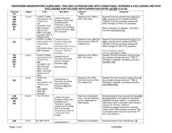
User manual Tria 6000/700 S TTLSafety Precautions and Warning NoticesThe warning notices are marked with the following danger icons andsignal words according to severity:Danger iconSignal word ExplanationDANGERWarning of danger which can lead tomajor or fatal injuries if disregarded.WARNINGWarning of danger which can lead tomajor or fatal injuries if disregarded.CAUTIONWarning of danger which can lead toinjuries if precautions are disregarded.CAUTIONWarning of danger which can lead toproperty damage if disregarded.Structure of Warning NoticesWarning notices are indicated by separation lines above and below. Theyare structured according to the following principle:SIGNAL WORD4Type and Source of DangerExplanations of the type and source of danger Measures to avert dangerHENSEL-VISIT GmbH & Co. KG
User manual Tria 6000/700 S TTLBasic Safety InstructionsSafety HintsHints Pertaining to Emitted Optical RadiationElectrical power is changed inside the flash tube to intensive opticalradiation: Do not flash directly into eyes from a short distance because theemitted intensive optical radiation can cause eye and skin damage. Do not look directly into flash reflector; the flash may beaccidentally triggered. In case of damage to skin or eyes caused by intensive opticalradiation consult a physician immediately.Working in PotentiallyPotentially Explosive RoomsWorking in potentially explosive rooms and environments is prohibitedbecause small sparks develop upon triggering the flash. Never work in potentially explosive environments. Do not work near flammable material. Do not store flammable material in direct vicinity of flash generatorsand flash lamps to avoid fire hazards.Ozone FormationFormationClosed rooms must be ventilated frequently to prevent excessive ozoneformation which can result from to the use of strong flash units.Protecting EquipmentEquipment from Moisture and SplashWaterFlash units need to be protected from moisture, wetness and splash water.Therefore, please do not place containers with liquids on the flash units.Connecting AccessoriesDo not connect accessories from other manufacturers, even if these looksimilar or identical.HENSEL-VISIT GmbH & Co. KG5
User manual Tria 6000/700 S TTLNot in Use DuringDuring Dust DevelopmentEquipment that is not in use when doing work that results in strong dustdevelopment needs to be covered with suitable dust protection.Safety Hints Pertaining to the Electrical SystemContact with the flash generator’s capacitor voltage is life threatening.Therefore, opening the housing and repairs may only be done byauthorized customer service personnel: Never open the device – high voltage, risk of death! The unit may only be connected to a power supply with workingequipment grounding conductor. Use only lamp plugs with flawless contacts. Burned down orcorroded plug contacts may cause a fire. Defective plugs may lead to defective plug sockets. To prevent damages, avoid leading cables across floors. If thiscannot be avoided, make sure that the cable is not damaged byvehicles, ladders, etc. Damaged cables and housings need to bereplaced immediately by authorized customer service personnel.Explosion of FlashFlash TubeThe flash tube is filled with xenon gas. There is negative pressure insidethe flash tube. Plasma develops during flashing due to electrical energybeing changed to radiation. This plasma development then causespositive pressure inside the flash tube. At the same time, the glass tube isexposed to strong mechanical forces. Minimal defects of the fused quartzglass, visually impossible to notice, may possibly lead to the explosion ofthe flash tube. In case the flash tube explodes, there is a danger of tiny glassparticles flying around. The user of this equipment needs to makesure that he/she is protected (e.g. by wearing a pair of safetygoggles).6HENSEL-VISIT GmbH & Co. KG
User manual Tria 6000/700 S TTL The flash tube can only explode during the flash process.Therefore, the flash head should never be directed at a personduring flashing. Immediately disconnect the flash head from the generator if theflash tube becomes damaged. Electrodes carry high voltage! Flash tubes must only be changed by authorized and trainedpersonnel. The flash tube must only be changed after the device isdisconnected from the power supply and is completely discharged.HENSEL-VISIT GmbH & Co. KG7
User manual Tria 6000/700 S TTLPrefaceDear customer,By purchasing the power pack Tria 6000/700 S TTL you have selected ahigh quality and high performance product.Below, we want to give you some details and hints on how to use this unitthat will ensure successful and productive work with it in the coming years.Observing the information below entitles you to guarantee adjustments,prevents damages, and extends the operational life of the unit.HENSEL-VISIT made all efforts to produce a safe and high-quality piece ofequipment while observing all current rules and regulations. Stringentquality checks ensure our high quality standard even in large-scaleproduction. Please do your part and treat the equipment with thenecessary care.In case of questions regarding the use of this equipment, feel free to callus any time.HENSEL-VISIT GmbH & Co. KG8HENSEL-VISIT GmbH & Co. KG
User manual Tria 6000/700 S TTLTable of ContentsFor Your Safety. 3Safety Precautions and Warning Notices . 4Structure of Warning Notices . 4Basic Safety Instructions . 5Safety Hints Pertaining to Emitted Optical Radiation . 5Working in Potentially Explosive Rooms . 5Ozone Formation . 5Protecting Equipment from Moisture and Splash Water . 5Connecting Accessories . 5Not in Use During Dust Development . 6Safety Hints Pertaining to the Electrical System . 6Explosion of Flash Tube . 6Preface . 8Description of Service . 12Proper Use. 12Following the Instructions . 12Technical Data . 13Equipment Description . 14User Panel . 16Scope of Delivery. 17Preparing for Initial Use . 18Connecting a Flash Head . 18Power Supply . 18Switch On . 19Test Flash . 20Performance Output Adjustment . 21Manual Flash Trigger . 22Slow . 23HENSEL-VISIT GmbH & Co. KG9
User manual Tria 6000/700 S TTLAudio . 24Flash Check . 25Modeling Light . 26Turn on the modeling light . 26Mode FREE . 27Mode PROP . 28BIAS . 29Connecting Flash Heads . 30Switch Off and Unplug the Mains Cord . 30Flash Channels . 30Connect the Mains Cord and Switch On. 31Test Flash . 32Synchronization . 33Synchronization via Cord . 33Synchronization via Slave . 35Synchronisation via the RS485 Interface . 35Identification Number . 36Replacing Fuses of Modeling Light . 37Switch Off and Unplug the Mains Cord . 37Exchange of Fuses . 38Connect the Mains Cord and Switch On. 39Preparation for Storage or Transport . 40Switch Off and Unplug the Mains Cord . 40Cleaning . 41Maintenance Plan . 41Periodic Inspections . 41Error Codes . 42Er 01 to Er 07: Ignition Error – Unit does Not Flash . 43Er 21 to Er 34: Temperature Error – Unit is too hot. 4310HENSEL-VISIT GmbH & Co. KG
User manual Tria 6000/700 S TTLEr 40 bis Er 43: Charge and Discharge Error . 44Customer Service . 45Disposal . 45Contact Information . 46Warranty . 47Limits of Liability . 47HENSEL-VISIT GmbH & Co. KG11
User manual Tria 6000/700 S TTLDescription of ServiceThe power pack Tria 6000/700 S TTL stores 6 kJ electrical energy with acharging voltage of 700 V.It has a flash head connector to which the maximum energy of 6kJ issupplied and two connectors at which 3 kJ can be delivered to the flashheads connected to these channels.The flashes can be triggered via a 5V TTL input. With the integrated RS485 interface, the functions of the power pack can be controlled by acomputer.Proper UseThe power pack Tria 6000/700 S TTL stored electrical energy which issupplied to the connected flash heads for technical applications.Following the InstructionsInstructionsFollowing the instruction manual and all other pertinent documents is partof the intended use.12HENSEL-VISIT GmbH & Co. KG
User manual Tria 6000/700 S TTLTechnical DataUnit series/Unit typeTria 6000/700 S TTLArticle number22063Stored energy6 kJMaximum flash energyConnector type of flash cableMains supplyFuses, inside the building6,000 J20 pole long plug230 V / 50 Hz16 A, characteristic B or CSynchsocket/ -voltage6.3 mm, mono/18 V or TTL / 5 VFeaturesAPD, BNC-plug (trigger with risingor falling edge), RS484 interfaceWeightOverall dimension in cmapprox. 17.1 kgLxWxH 34,5 x 19,5 x 44Technical modifications excepted.The listed data are standard values which may deviate depending on component tolerances.HENSEL-VISIT GmbH & Co. KG13
User manual Tria 6000/700 S TTLEquipment DescriptionHandleUser panelSwitch for rising or falling edgeOpening for ventilationBumperSpare fuses inside the handleBumperHandleBumperOpening for ventilation14HENSEL-VISIT GmbH & Co. KG
User manual Tria 6000/700 S TTLSpare fuses inside the handleSwitch for rising or falling edgeBumperBumperOpening for ventilationSecurity hintsLabel with type and serial numberHensel-Visit GmbH & Co. KG15
User manual Tria 6000/700 S TTLUser PanelFuseModeling lightSocket formains VEKeyAUDIOKeySLOW KeyFREE /PROP KeyTESTKeyIndicatorfor flashreadynessDisplay offlash outputFlash outputcontrolSocket forflash lampsSwitch for flashchannels16Modelinglight ON/OFFDisplayModeling lightRS 485interfaceModelinglight controlID KeySlaveDisplayfor IDHENSEL-VISIT GmbH & Co. KG
User manual Tria 6000/700 S TTLScope of DeliveryDeliveryThe standard scope of delivery includes: 1 power pack Tria 6000/700 S TTL 1 Set of cables, consisting of mains and synch cord 1 User manualHensel-Visit GmbH & Co. KG17
User manual Tria 6000/700 S TTLPreparing for Initial UsePlease unpack the flash unit and control the completeness according toscope of delivery. If something is missing, please get in contact with yourdealer.For the following steps we recommend that you place the flash unit on aflat surface or mount it to a stand mount.Connecting a Flash HeadLamp cable Plug the lamp cable into theadapter socket 1 of thepower pack. Connect the lamp cable withthe flash head. Please read the user manualof the flash head.Power SupplyCAUTIONSystem may get damagedThe system can be damaged during connecting to thepower supply. Check listed mains supply on type label of theunit. Only connect to grounded power supply. Plugs must be secured at building side with 16A at 230 V and with 20 A at 110 V.18HE sh unitHeat which may cause burns develops at the headduring the flash process. Before removing the reflector allow reflectorand flash unit to cool off.Switch Off and Unplug the Mains CordPower switchMains cord Turn the unit off by pressingthe power switch. Unplug the mains cord fromthe mains supply socket. Unplug the mains cord fromthe mains adapter socket ofthe compact flash unit.40HENSEL-VISIT GmbH & Co. KG
User manual Tria 6000/700 S TTLCleaningDANGERDanger of electric shockDanger of electric shock exists during installation andremoval of system components. Switch off unit via the power switch. Disconnect the unit from the mains voltage. Wait 15 minutes for the discharge of thecapacitors.CAUTIONRisk of burns from reflector and flash unitHeat which may cause burns develops at the headduring the flash process. Before removing the reflector allow reflectorand flash unit to cool off.The flash unit needs little maintenance by the user. The outside of theequipment must be cleaned periodically of dust and dirt to ensure electricsafety.Maintenance PlanPlanClean the system regularly as described in the section ’Cleaning’.Periodic InspectionsInspectionsNational safety regulations require that electric systems and devices beinspected and maintained in regular intervals. Devices and accessoriesmust be checked regularly for operational safety. An annual inspection ofthe system insures the safety of the user and retains the value of theequipment.HENSEL-VISIT GmbH & Co. KG41
User manual Tria 6000/700 S TTLError CodesDisplayIn case of an error, an error code isshown in display. In this caseproceed as follows: Switch off the unit. Wait a few seconds. Switch the unit on again.If the error code persists, check if the problem can be remedied accordingto the following list or contact cu
User manual Tria 6000/700 S TTL 8 HENSEL-VISIT GmbH & Co. KG Preface Dear customer, By purchasing the power pack Tria 6000/700 S TTL you have selected a high quality and high performance product. Below, we want to give you some details and hints on how to use this unit that will ensure successful and productive work with it in the coming years. .
