Transcription
ii
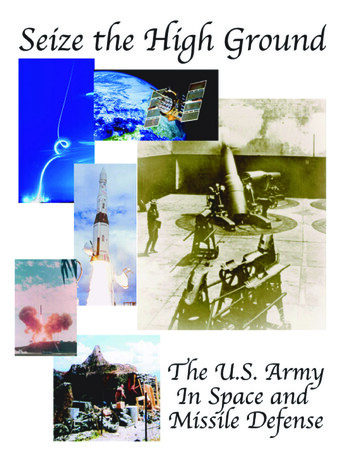
Seize the High GroundThe Army in Space and Missile DefenseNIKE - ZEUS1957-1964SAFEGUARD Systems Command1969-1974Space and Missile Defense Command2001-PresentbyDr. James WalkerDr. Lewis BernsteinMrs. Sharon LangHistorical OfficeU.S. Army Space and Missile Defense Command2003
ii
Table of ContentsChapterPageThe Commander’s Introduction . xvPreface and Acknowledgements .xviiIntroductionA Historical Perspective of Missile Defense and Space . 1Chapter I.Aircraft, Rockets, Missiles and Radar, 1907-1961 . 15Chapter II.Rockets, Communications and Deploying Ballistic Missile Defense,1958-1975 . 37Chapter III.Communications, Sensors, Maintaining Interest in Missile Defenseand the Strategic Defense Initiative, 1970-1989 . 83Chapter IV.Renewed Interest in Space and The War in the Persian Gulf,1985-1991 . 145Chapter V.New Ideas about Space and Missile Defense After the War,1991-1997 . 167Chapter VI.The Army’s Newest Major Command and a Different Tack on Spaceand Missile Defense Organizations, 1995-present . 207ConclusionConclusion. 253BibliographyBibliography . 257Appendix A.Commanders and Directors .A-1Appendix B.Army Space and Missile Defense Chronology. B-1Appendix C.Army Astronaut Missions . C-1Appendix D.Acronyms .D-1
ii
List of IllustrationsFigurePageFig. 1-1. V-1 flying bomb over residential area of London. .17Fig. 1-2. Launch of a V-2 rocket. .18Fig. 1-3. 120 mm gun in Chicago. .22Fig. 1-4. The 75mm Skysweeper antiaircraft gun was the last conventional antiaircraft artillery weapon issuedto ARADCOM. In this photo, soldiers practice with a Skysweeper at White Sands. .23Fig. 1-5. In June 1958, the first NIKE-HERCULES unit reached operational readiness status in Chicago.NIKE-HERCULES crew scrambles during exercises in Chicago. .25Fig. 1-6. An Explorer satellite atop a Jupiter-C rocket. .28Fig. 1-7. Major General John C. Medaris, one of the founders of the Army’s missile program. .29Fig. 2-1. Emblem of the NIKE-ZEUS Project Office. .39Fig. 2-2. Brigadier General Ivey Drewry became the first NIKE-ZEUS Project Manager in August 1962.Brigadier General Drewry led the Army’s missile defense program until his retirement inNovember 1967. .39Fig. 2-3. The NIKE Family of missiles. From back to front: NIKE-AJAX, NIKE-HERCULES andNIKE-ZEUS. .40Fig. 2-4. Testing began at the Kwajalein Missile Range in December 1961. This aerial view shows theisland in January 1962. .41Fig. 2-5. A map of the facilities at the Kwajalein Complex in the 1960s. .42Fig. 2-6. Pictured are the many different radars of the NIKE-ZEUS system. The photo was taken atKwajalein, 20 July 1963. .43Fig. 2-7. Artist’s conception of the target track radar and the target intercept computer. .44Fig. 2-8. On 12 December 1962, the NIKE-ZEUS Project Office achieved the first fully successful interceptof an ICBM, seen in the horizon over the ZEUS Acquisition Radar. .45Fig. 2-9. An annotated photograph illustrating the Army’s successful ICBM intercept. .45Fig. 2-10. A NIKE-ZEUS missile on a launcher during testing at White Sands Missile Range. .46Fig. 2-11. Emblem of the NIKE-X Project Office, which replaced NIKE-ZEUS in February 1964. .49Fig. 2-12. Dual salvo launch seen near the headquarters of the NIKE-X Project Kwajalein Test Site. .50Fig. 2-13. The Sentinel became the new symbol of the organization in 1967. .54v
Fig. 2-14. SENTINEL sites were established to defend urban and industrial areas. The map does not showthe sites in Washington, D.C. and Fairbanks, Alaska that were never publicly announced. .55Fig. 2-15. The elliptical footprint of the area covered by a SPARTAN missile system from a hypotheticalbase in Iowa. .57Fig. 2-16. The control and guidance sections of the SPARTAN missile are loaded into a launch cell on MeckIsland. .57Fig. 2-17. Artist’s conception of the SPRINT and SPARTAN engagement concept from a coastalSENTINEL battery. .58Fig. 2-18. SPRINT test vehicle #2 on 4 June 1965 at White Sands Missile Range. .59Fig. 2-19. SPRINT missile in launch cell for FLA-1 on 16 November 1965. .60Fig. 2-20. The Multifunction Array Radar was constructed at White Sands Missile Range. .61Fig. 2-21. Artist’s concept of the Perimeter Acquisition Radar. .61Fig. 2-22. Cut-away drawing of the tactical Missile Site Radar. .63Fig. 2-23. The Institute of Heraldry issued this shoulder sleeve insignia on 8 May 1969. It remained asymbol of this organization until the mid-1990s. .63Fig. 2-24. The initial SAFEGUARD deployment, proposed in 1969, with the first two approved sites circled. .65Fig. 2-25. Phase Two of the SAFEGUARD deployment with the four authorized sites circled. .66Fig. 2-26. Tying rebar - construction began on the nuclear hardened facilities in 1970. .68Fig. 2-27. Despite weather conditions, which ranged from -40 F to 100 F, the Top-Out Pour for the MissileSite Control Building took place on 12 October 1971. .69Fig. 2-28. Lieutenant General Stanley R. Mickelsen (1895-1966) recognized for his support of the BallisticMissile Defense Program. .70Fig. 2-29, 30. As construction progressed in North Dakota, missile testing continued on Kwajalein. TheSPARTAN missile is launched from Mount Olympus. The final SPARTAN launch (M2-25)occurred on 17 April 1975. .72Fig. 2-31, 32. During flight, the SPRINT missile achieved such speeds that it would become incandescent.SAFEGUARD tests included salvo tests for both missiles. A SPRINT salvo launch. .73Fig. 2-33, 34. Site plans for the MSR and the PAR illustrate the vastness of the complex. The MSR complexat 433 acres was much larger than the PAR which encompassed 279 acres. .74Fig. 2-35. The PAR building, the largest radar facility of its kind measures one acre at its base and has theequivalent height of a 12-story building. The PAR is now operated by the U.S. Air Force. .75Fig. 2-36. Four remote SPRINT launch sites equipped with 12-16 SPRINT launch stations providedadditional protection. .75vi
Fig. 2-37. The SAFEGUARD site became the western world’s only operational ABM site. The MSR and itsmissile silos stand ready to protect the nation. .76Fig. 3-1. The artist’s drawing illustrates the system elements of the Site Defense concept and its proposeddeployment within the defense unit. .84Fig. 3-2. Computer systems play vital roles in missile defense. One such system for Site Defense was thisCDC-76-computer, which was operated and maintained by the control consoles in theforeground-May 1974. .85Fig. 3-3. Data collected during reentry measurement studies are important to a successful intercept. Reentryvehicles blaze through the skies over Kwajalein. .87Fig. 3-4. The Designating Optical Tracker (DOT) enjoyed a perfect test record and demonstrated the viabilityof the onboard infrared optics technology. The DOT on its launch pad at the Kwajalein MissileRange. .89Fig. 3-5. The DOT sensor package recovered from the Pacific to be prepared for the next test. .90Fig. 3-6. The Optical Aircraft Measurements Program was an airborne sensor installed into a U.S. Air Forceaircraft. .91Fig. 3-7. The Advanced Research Center’s simulations capabilities have applications to all of the services.Soldiers from this command practice battle management techniques. .92Fig. 3-8. Designed to protect the Air Force’s MX missiles, the LoAD/SENTRY was to be a mobile defensiveinterceptor. .94Fig. 3-9. This drawing illustrates the differences between the SPRINT, developed in the 1960s, and the smallerLoAD, a product of the 1970s. .95Fig. 3-10. Noted for its distinctive web (insert) designed to capture an RV, the Homing Overlay Experimentachieved the first kinetic energy intercept colliding with its target at a speed of 20,000 mph. .97Fig. 3-11. This 27 June 1987 flight of the FLAGE shows the second successful intercept of the FLAGEprogram, a simulated RV launched from an aircraft.98Fig. 3-12. Guided by 216 attitude control motors, the Flexible Lightweight Agile Guided Experimentdemonstrated the feasibility of kinetic energy intercepts at short ranges. .99Fig. 3-13. "They Shall Not Pass" - is the motto on the distinctive unit insignia created in 1987 for theUSASDC. The illustration symbolizes the defensive shield protecting the world from anincoming threat. .106Fig. 3-14. The SDIO program called for a multi-phase strategic defense. The layered architecture addressedthe boost, mid-course and terminal phases of the target missile’s flight. .108Fig. 3-15. This diagram of the Systems Architecture Concepts attributes projects to the appropriate service ororganization. .108Fig. 3-16. On 29April 1986, the
SPARTAN missile is launched from Mount Olympus. The final SPARTAN launch (M2-25) occurred on 17 April 1975. .72 Fig. 2-31, 32. During flight, the SPRINT missile achieved such speeds that it would become incandescent. SAFEGUARD tests included salvo tests for both missiles. A SPRINT salvo launch. .73 Fig. 2-33, 34. Site plans for the MSR and the PAR illustrate the vastness of the complex .