Transcription
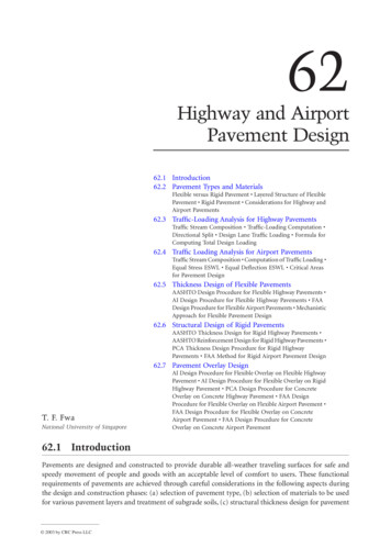
62Highway and AirportPavement Design62.1 Introduction62.2 Pavement Types and MaterialsFlexible versus Rigid Pavement Layered Structure of FlexiblePavement Rigid Pavement Considerations for Highway andAirport Pavements62.3 Traffic-Loading Analysis for Highway PavementsTraffic Stream Composition Traffic-Loading Computation Directional Split Design Lane Traffic Loading Formula forComputing Total Design Loading62.4 Traffic Loading Analysis for Airport PavementsTraffic Stream Composition Computation of Traffic Loading Equal Stress ESWL Equal Deflection ESWL Critical Areasfor Pavement Design62.5 Thickness Design of Flexible PavementsAASHTO Design Procedure for Flexible Highway Pavements AI Design Procedure for Flexible Highway Pavements FAADesign Procedure for Flexible Airport Pavements MechanisticApproach for Flexible Pavement Design62.6 Structural Design of Rigid PavementsAASHTO Thickness Design for Rigid Highway Pavements AASHTO Reinforcement Design for Rigid Highway Pavements PCA Thickness Design Procedure for Rigid HighwayPavements FAA Method for Rigid Airport Pavement Design62.7 Pavement Overlay DesignT. F. FwaNational University of SingaporeAI Design Procedure for Flexible Overlay on Flexible HighwayPavement AI Design Procedure for Flexible Overlay on RigidHighway Pavement PCA Design Procedure for ConcreteOverlay on Concrete Highway Pavement FAA DesignProcedure for Flexible Overlay on Flexible Airport Pavement FAA Design Procedure for Flexible Overlay on ConcreteAirport Pavement FAA Design Procedure for ConcreteOverlay on Concrete Airport Pavement62.1 IntroductionPavements are designed and constructed to provide durable all-weather traveling surfaces for safe andspeedy movement of people and goods with an acceptable level of comfort to users. These functionalrequirements of pavements are achieved through careful considerations in the following aspects duringthe design and construction phases: (a) selection of pavement type, (b) selection of materials to be usedfor various pavement layers and treatment of subgrade soils, (c) structural thickness design for pavement 2003 by CRC Press LLC
62-2The Civil Engineering Handbook, Second Editionlayers, (d) subsurface drainage design for the pavement system, (e) surface drainage and geometric design,and (f ) ridability of pavement surface.The two major considerations in the structural design of highway and airport pavements are materialdesign and thickness design. Material design deals with the selection of suitable materials for variouspavement layers and mix design of bituminous materials (for flexible pavement) or portland cementconcrete (for rigid and interlocking block pavements). These topics are discussed in other chapters ofthis handbook. This chapter presents the concepts and methods of pavement thickness design. As thename implies, thickness design refers to the procedure of determining the required thickness for eachpavement layer to provide a structurally sound pavement structure with satisfactory performance for thedesign traffic over the selected design life. Drainage design examines the entire pavement structure withrespect to its drainage requirements and incorporates facilities to satisfy those requirements.62.2 Pavement Types and MaterialsFlexible versus Rigid PavementTraditionally, pavements are classified into two categories, namely flexible and rigid pavements. The basisfor classification is the way by which traffic loads are transmitted to the subgrade soil through thepavement structure. As shown in Fig. 62.1, a flexible pavement provides sufficient thickness for loaddistribution through a multilayer structure so that the stresses and strains in the subgrade soil layers arewithin the required limits. It is expected that the strength of subgrade soil would have a direct bearingon the total thickness of the flexible pavement. The layered pavement structure is designed to takeadvantage of the decreasing magnitude of stresses with depth.A rigid pavement, by virtue of its rigidity, is able to effect a slab action to spread the wheel load overthe entire slab area, as illustrated in Fig. 62.1. The structural capacity of the rigid pavement is largelyprovided by the slab itself. For the common range of subgrade soil strength, the required rigidity for aportland cement concrete slab (the most common form of rigid pavement construction) can be achieved(a) Typical Cross Section of Flexible Pavement(b) Load Transmission in Flexible PavementHighway AirportPavement PavementTack CoatPrime CoatWearing Course1-2 inBinder Course2-4 inBase Course4-12 in6-12 in12-18 in12-36 in6-24 in12-60 inSubbase CoursePrepared SubgradeNatural SubgradeWheelLoad3-6 in(1 in 25.4 mm)(c) Typical Cross Section of Rigid Pavement(d) Load Transmission in Rigid PavementHighway AirportPavement PavementConcrete SlabBase or SubbasePrepared SubgradeNatural SubgradeFIGURE 62.1 Flexible and rigid pavements.6-12 in10-24 in4-6 in4-12 in6-12 in9-18 in(1 in 25.4 mm)WheelLoad
62-3Highway and Airport Pavement Designwithout much variation in slab thickness. The effect of subgrade soil properties on the thickness of rigidpavement is therefore much less important than in the case of flexible pavement.Layered Structure of Flexible PavementSurface CourseIn a typical conventional flexible pavement, known as asphalt pavement, the surface course usuallyconsists of two bituminous layers — a wearing course and a binder course. To provide a durable,watertight, smooth-riding, and skid-resistant traveled surface, the wearing course is often constructed ofdense-graded hot mix asphalt with polish-resistant aggregate. The binder course generally has largeraggregates and less asphalt. The composition of the bituminous mixtures and the nominal top sizeaggregates for the two courses are determined by the intended use, desired surface texture (for the caseof wearing course), and layer thickness. A light application of tack coat of water-diluted asphalt emulsionmay be used to enhance bonding between the two courses. Table 62.1 shows selected mix compositionslisted in ASTM Standard Specification D3515 [1992]. Open-graded wearing courses, some with air voidexceeding 20%, have also been used to improve skid resistance and reduce splash during heavy rainfallby acting as a surface drainage layer.Base CourseBase and subbase layers of the flexible pavement make up a large proportion of the total pavementthickness needed to distribute the stresses imposed by traffic loading. Usually base course also serves asa drainage layer and provides protection against frost action. Crushed stone is the traditional materialused for base construction to form what is commonly known as the macadam base course. In thisconstruction, choking materials consisting of natural sand or the fine product resulting from crushingcoarse aggregates are added to produce a denser structure with higher shearing resistance. Such basecourses are called by different names, depending on the construction method adopted.Dry-bound macadam is compacted by means of rolling and vibration that work the choking materialsinto the voids of larger stones. For water-bound macadam, after spreading of the choking materials, wateris applied before the entire mass is rolled. Alternatively, a wet-mix macadam may be used by premixingcrushed stone or slag with a controlled amount of water. The material is spread by a paving machineTABLE 62.1Example Composition of Dense Bituminous Paving MixturesMix Designation and Nominal Maximum Size of AggregateSieve Size2½ in.2 in.1½ in.1 in.3/4 in.1/2 in.3/8 in.No. 4No. 8No. 16No. 30No. 50No. 100No. 2002 in.(50 mm)1½ in.(37.5 mm)1 in.(25.0 mm)3/4 in.(19.0 mm)1/2 in.(12.5 mm)3/8 in.(9.5 ��10055–8532–67——7–23—2–10Note: Numbers in table refer to percent passing by weight.Source: ASTM, Standard Specification D3515-84, Annual Book of ASTM Standards, Vol. 04.03 —Road and Paving Materials; Travelled Surface Characteristics, 1992. With permission.
62-4The Civil Engineering Handbook, Second EditionTABLE 62.2(a) Grading Requirements for Unbound Subbase and BaseMaterials — ASSHTO Designation M147-65 (1989)Grading: Percentage PassingSieve Size50 mm25 mm9.5 mm4.75 mm2 mm425 mm75 100—70–10055–10030–708–25Other requirements:1. Coarse aggregate ( 2 mm) to have a percentage wear by Los Angelestest not more than 50.2. Fraction passing 425-mm sieve to have a liquid limit not greater than25% and a plasticity index not greater than 6%.Source: AASHTO Designation M147-65, AASHTO Standard Specificationsfor Transportation Materials and Methods of Sampling and Testing, AmericanAssociation of State Highway and Transportation Officials, Washington, D.C.,1989. With permission.TABLE 62.2(b) ASTM DesignationD2940-74 (Reapproved 1985)Grading: Percentage PassingSieve SizeBasesSubbases50 mm37.5 mm19 mm9.5 mm4.75 mm600 mm75 0–100——30–60—0–12Other requirements:1. Fraction passing the 75-mm sieve not toexceed 60% of the fraction passing the600-mm sieve.2. Fraction passing the 425-mm sieve shallhave a liquid limit not greater than 25%and a plasticity index not greater than 4%.Source: ASTM. 1992. ASTM Standard Specification D2940-74 (reapproved 1980), Annual Bookof ASTM Standards. Vol. 04.03 — Road and Paving Materials; Travelled Surface Characteristics,1992. With permission.and compacted by a vibrating roller. Table 62.2 shows specifications for unbound base and subbasematerials specified by AASHTO and ASTM.Granular base materials may be treated with either asphalt or cement to enhance load distributioncapability. Bituminous binder can be introduced by spraying heated asphalt cement on consolidated androlled crushed stone layer to form a penetration macadam road base. Alternatively, bituminous roadbases can be designed and laid as in the case for bituminous surface courses. Cement-bound granularbase material is plant mixed with an optimal moisture content for compaction. It is laid by paver andrequires time for curing. Lean concrete base has also been used successfully under flexible pavements.Table 62.3 shows examples of grading requirements for these materials.
62-5Highway and Airport Pavement DesignTABLE 62.3Requirements for Stabilized Base CoursesCement TreatedSpecificationClass AClass BBituminous TreatedClass CClass 1Class 2Lime Treated(a) Stabilized Base Courses for Flexible PavementsPercent passing2½ in.3/4 in.No. 4No. 10No. 40No. 2007-day fc (psi)S (lb)F (0.01 ——12 �10075–9525–6015–458–302–15———750 min16 max6 max500 min20 max6 max——6 maxSpecificationType A(OpenGraded)Type B(DenseGraded)Type C(CementGraded)Type D(LimeTreated)Type E(BituminousTreated)Type F(Granular)(b) Base Materials for Concrete PavementPercent passing1½ in.3/4 in.No. 4No. 40No. ��125–20——(The minus No. 200 material should be held to a practical minimum)28-day fc (psi)——400–750100—S (lb)————500 minF (0.01 in.)————20 maxSoil constants:LL25 max25 max———PI*N.P.6 max10 max—6 max100—65–10025–500–15———25 max6 maxNotes:*To be determined by complete laboratory analysis, taking into consideration the ability of thestabilized mixture to resist underslab erosion.fc compressive strength as determined in unconfined compression tests on cylinders 4 inches indiameter and 4 inches high. Test specimens should contain the same percentage of portlandcement and be compacted to the same density as achieved in construction.S Marshall stability.F Marshall flow.PI plasticity index performed on samples prepared in accordance with AASHTO DesignationT-87 and applied to aggregate prior to mixing with the stabilizing admixture, except that, inthe case of lime-treated base, the value is applied after mixing.LL liquid limit.Source: AASHTO Interim Guide for Design of Pavement Structures, American Association of StateHighway and Transportation Officials, Washington, D.C., 1972. With permission.Subbase CourseThe subbase material is of lower quality than the base material in terms of strength, plasticity, andgradation, but it is superior to the subgrade material in these properties. It may be compacted granularmaterial or stabilized soil, thus allowing building up of sufficient thickness for the pavement structureat relatively low cost. On a weak subgrade, it also serves as a useful working platform for constructingthe base course. Examples of grading requirements for subbase materials are given in Table 62.2. The
62-6COMPACTED SUBGRADE DEPTH-COHESIVE SOILS-INCHESGROSS AIRCRAFT WEIGHT-DUAL TANDEM GEAR-1000 POUNDS40020025030035015015595% COHESIVE100% NONCOHESIVE20251090% 80COMPACTED SUBGRADE DEPTH-NONCOHESIVE SOILS-INCHESThe Civil Engineering Handbook, Second Edition75110140170200230GROSS AIRCRAFT WEIGHT-DUAL GEAR-1000 POUNDSFIGURE 62.2 Subgrade compaction requirements for flexible airport pavements. (Source: Federal Aviation Administration, Airport Pavement Design and Evaluation, Advisory Circular AC 150/5320-6C, 1978, p. 41. With permission.)subbase course may be omitted if the subgrade soil satisfies the requirements specified for subbasematerial.Prepared SubgradeMost natural soils forming the roadbed for pavement construction require some form of preparation ortreatment. The top layer of a specified depth is usually compacted to achieve a desired density. The depthof compaction and the compacted density required depend on the type of soil and magnitudes of wheelloads and tire pressures. For highway construction, compaction to 100% modified AASHTO densitycovering a thickness of 12 in. (300 mm) below the formation level is commonly done. Compaction depthof up to 24 in. (600 mm) may be required for heavily trafficked pavements. For example, in the case ofcohesive subgrade, the Asphalt Institute [1991] requires a minimum of 95% of AASHTO T180(Method D) density for the top 12 in. (300 mm) and a minimum of 90% for all fill areas below the top12 in. (300 mm). For cohesionless subgrade, the corresponding compaction requirements are 100 and95%, respectively.Due to the higher wheel loads and tire pressures of aircraft, many stringent compaction requirementsare found in airport pavement construction. Figure 62.2 shows an example of the compaction requirements recommended by the FAA [1978].In some instances it may be economical to treat or stabilize poor subgrade materials and reduce thetotal required pavement thickness. Portland cement, lime, and bitumen have all been used successfullyfor this purpose. The choice of the method of stabilization depends on the soil properties, improvementexpected, and cost of construction.Rigid PavementRigid pavements constructed of portland cement concrete are mostly found in heavy-traffic highwaysand airport pavements. To allow for expansion, contraction, warping, or breaks in construction of the
Highway and Airport Pavement Design62-7concrete slabs, joints are provided in concrete pavements. The joint spacing, which determines the lengthof individual slab panels, depends on the use of steel reinforcements in the slab. The jointed plain concretepavement (JPCP), requiring no steel reinforcements and thus the least expensive to construct, is a popularform of construction. Depending on the thickness of the slab, typical joint spacings for plain concretepavements are between 10 and 20 ft (3 and 6 m). For slabs with joint spacing greater than 6 m, steelreinforcements have to be provided for crack control, giving rise to the use of jointed reinforced concretepavements (JRCP) and continuously reinforced concrete pavements (CRCP). Continuously reinforced concrete pavements usually contain higher than 0.6% steel reinforcement to eliminate the need to providejoints other than construction and expansion joints.The base course for rigid pavement, sometimes called subbase, is often provided to prevent pumping(ejection of foundation material through cracks or joints resulting from vertical movement of slabs undertraffic). The base course material must provide good drainage and be resistant to the erosive action ofwater. When dowel bars are not provided in short jointed pavements, it is common practice to constructcement-treated base to assist in load transfer across the joints.Considerations for Highway and Airport PavementsThe two pavement types, flexible and rigid pavement, have been used for road and airport pavementconstruction. The choice of pavement type depends on the intended functional use of the pavement(such as operating speed and safety requirements), types of traffic loading, cost of construction, andmaintenance consideration.The main differences in design considerations for highway and airport pavements arise from thecharacteristics of traffic using them. Over the typical design life span of 10 to 20 years for flexiblepavements, or 20 to 40 years for rigid pavements, a highway pavement will be receiving highly channelizedwheel load applications in the millions. Consideration of the effects of load repetitions — such ascumulative permanent deformation, crack propagation, and fatigue failure — becomes important. Thetotal number of load applications in the entire design life of a highway pavement must therefore beknown for pavement structural design. In contrast, the frequency of aircraft loading on airport pavementis much less. There are also the so-called wander effect of aircraft landing and taking off and the largevariation in the wheel assembly configurations and layout of different aircraft. These make wheel loadingon airport pavements less channelized than on highway pavements. Identification of the most criticalaircraft is therefore necessary for structural design of airport pavements.Another important difference is in the magnitude of wheel loads. Airport pavements receive loads farexceeding those applied on the highway. An airport pavement may have to be designed to withstandequivalent single wheel loads of the order of 50 t (approximately 50 tons), whereas the maximum singlewheel load allowed on the road pavement by most highway authorities is about 10 t (approximately10 tons). Furthermore, the wheel tire pressure of an aircraft of about 1200 kPa (175 psi) is nearly twicethe value of a normal truck tire. These differences greatly influence the material requirements for thepavements.62.3 Traffic Loading Analysis for Highway PavementsAlthough it is convenient to describe the design life of a pavement in years, it is the total traffic loadingduring service that determines the actual design life of the pavement. It is thus more appropriate toassociate the design life of a pavement with the total design traffic loading. For example, a pavementdesigned for 20 years with an assumed traffic growth of 4% will reach the end of its design life soonerthan 20 years if the actual traffic growth is higher than 4%.The ultimate aim of traffic analysis for pavement design is to determine the magnitudes of wheel loadsand the number of times each of these loads will be applied on the pavement during its design life. Forhighway pavements the computation of design traffic loading involves the following steps:
62-81.2.3.4.5.6.The Civil Engineering Handbook, Second EditionEstimation of expected initial year traffic volumeEstimation of expected annual traffic growth rateEstimation of traffic stream compositionComputation of traffic loadsEstimation of directional split of design traffic loadsEstimation of design lane traffic loadsInformation concerning the first two steps can be obtained from traffic surveys and forecasts basedon historical trends or prediction using transportation models. The analyses required for the remainingsteps are explained in the discussions that follow.Traffic Stream CompositionThe number of different types of vehicles — such as cars, buses, single-unit trucks, and multiple-unittrucks — expected to use the highways must be estimated. One may derive the vehicle-type distributionfrom results of classification counts made on similar highway type within the same region or from generaldata compiled by highway authorities, as illustrated in Table 62.4. However, as noted in the footnote ofthe table, individual situations may differ from the average values by 50% or more.TABLE 62.4Asphalt Institute Data for Truck Loading ComputationAverage TrucksInterstateRuralTruck ClassOtherRuralAllRuralAllUrbanAllSystem(a) Average Distribution on Different Classes of Highways (U.S.)Single-unit trucks2 axle, 4 tire2 axle, 6 tire3 axle or moreAll single-unitMultiple-unit trucks3 axle4 axle5 axle or moreAll multiple-unitAll 132327100143641100141823100143237100(b) Average Truck Factors (TF) for DifferentClasses of Highways and Vehicles (U.S.)Single-unit trucks2 axle, 4 tire2 axle, 6 tire3 axle or moreAll single-unitMultiple-unit trucks3 axle4 axle5 axle or moreAll multiple-unitAll 0.891.021.000.300.480.730.950.950.40Note: Individual situations may differ from these average values by 50% ormore.Source: Asphalt Institute, Asphalt Technology and Construction Practices. Educational Series ES-1, 1983b. pp. J5–J7. With permission.
62-9Highway and Airport Pavement DesignTABLE 62.5 Vehicle Classification by Axle ConfigurationVehicleClassAxleConfigurationTotal No.of AxlesNumber ofSingle AxlesNumber ofTandem 55146411Source: Fwa, T.F. and Sinha, K.C., 1985. A Routine Maintenance and Pavement Performance Relationship Model for Highways, Report JHRP-85-11, Purdue University, WestLafayette, IN, 1985. With permission.Traffic-Loading ComputationTwo aspects of traffic loading are of concern in the structural design of highway pavements, namely, thenumber of applications and the magnitude of each load type. A traffic count survey that classifies vehiclesby axle configuration, as shown in Table 62.5, enables one to compute the number of repetitions by axletype (i.e., by single axle, tandem axle, and tridem axle). With this information, one must further subdivideeach axle type by load magnitude to arrive at a traffic-loading table such as that illustrated in Table 62.6.The combined loading effects of different axle types on pavements cannot be easily analyzed. In thelate 1950s, AASHO [Highway Research Board 1962] conducted the now well-known AASHO road testto provide, among other information, equivalency factors to convert one pass of any given single- ortandem-axle load to equivalent passes of an 18-kip (80 kN) single-axle load. The single-axle load of18 kip (80 kN) was arbitrarily chosen in the AASHO road test as the standard axle with a damaging effectof unity. The equivalency factor, known as the equivalent single-axle load (ESAL) factor, was derivedbased on the relative damaging effects of various axle loads. Table 62.7 presents the ESAL factors of axleloads for different thicknesses of flexible pavements with a terminal serviceability index of 2.5. Table 62.8presents the corresponding ESAL factors for rigid pavements.Another approach to computing the combined effect of mixed traffic is to adopt the hypothesis ofcumulative damage. For a given form of pavement damage, the allowable number of repetitions by eachvehicle type or load group is established separately. A damage ratio for vehicle type or load group i isdefined asDi ( ni § Ni )(62.1)
62-10The Civil Engineering Handbook, Second EditionTABLE 62.6Examples of Axle-Load Data PresentationSingle AxleTandem AxleAxle Load (kips)No. Axles/DayAxle Load (kips)No. Axles/DayLess than 1041994177986265939546where ni is the design repetitions and Ni the allowable repetitions. The total level of damage caused bythe mixed traffic is computed as the sum of damage ratios of all vehicle types or load groups.Example 62.1This example involves computation of the ESAL contribution of a passenger car, a bus, and a combinationtruck. The axle loads of the three fully laden vehicles are given as follows:Car. Front single axle 2 kips; rear single axle 2 kips.Bus. Front single axle 10 kips; rear single axle 8 kips.Truck. Front single axle 12 kips; middle single axle 18 kips; rear tandem axle 32 kips.Assuming a terminal serviceability index of 2.5, the ESAL contributions of the three vehicles can becomputed for a flexible pavement with structural number SN 5.0 [see Eq. (62.17) for definition of SN]and a rigid pavement of slab thickness equal to 10 in.For the ESAL on flexible pavement, Table 62.7 is used to obtain the ESAL factor for each axle. TheESAL contribution of the passenger car is (0.0002 0.0002) 0.0004. The ESAL contribution of the busis (0.088 0.034) 0.122. The contribution of the truck is (0.189 1.00 0.857) 2.046. Table 62.8is used for the ESAL computation in the case of rigid pavement. The ESAL contributions are (0.0002 0.0002) 0.0004 for the car, (0.081 0.032) 0.113 for the bus, and (0.175 1.00 1.50) 2.675 forthe truck.The ratios of ESAL contributions are (car):(bus):(truck) 5012:305:1 for flexible pavement and6688:283:1 for rigid pavement. It can be seen from this example that the damaging effects of a truck anda bus are, respectively, more than 5000 and 280 times that of a passenger car. This explains why passengercar volumes are often ignored in traffic-loading computation for pavement design.Example 62.2This example involves ESAL computation based on axle load data. Calculate the total daily ESAL of thetraffic-loading data of Table 62.6 for (a) a flexible pavement with structural number SN 5.0 [seeEq. (62.17) for definition of SN] and (b) a rigid pavement with slab thickness of 10 in. The design terminalserviceability index for both pavements is 2.5.The data in Table 62.6 are repeated in columns (1) and (2) of the following table. The ESAL factorsin column (3) are obtained from Table 62.7 (second part) for SN 5.0, and those in column (5) areobtained from Table 62.8 (second part) for slab thickness of 10 in. The ESAL contribution by each axle
62-11Highway and Airport Pavement Designgroup is computed by multiplying its ESAL factor by the number of axles per day. The total ESAL of thetraffic loading is 12,642 for the flexible pavement and 19,309 for the rigid pavement.Axle Load(kips)(1)*No. Axlesper 879235921041994177986265939546*Flexible PavementESAL Factor(3)Rigid PavementESAL(2) (3)ESAL 68Total 12,642.38ESAL(2) tal 19,309.39In column (1), the prefix S stands for single axle and T stands for tandem axle.TABLE 62.7Axle Load(kips)AASHTO Load Equivalency Factors for Flexible PavementsPavement Structural Number 6061.001.552.303.274.485.987.8(a) Single Axles and pt of 72.092.893.915.216.8
62-12The Civil Engineering Handbook, Second EditionTABLE 62.7 (continued) AASHTO Load Equivalency Factorsfor Flexible PavementsAxle Load(kips)32343638404244464850Pavement Structural Number 21.323.626.128.831.734.838.1(b) Tandem Axles and pt of 16.618.921.524.427.631
this handbook.This chapter presents the concepts and methods of pavement thickness design. As the name implies, thickness design refers to the procedu rdee oftermining the required thickness for each pavement layer to provide a structurally sound pavement structure with satisfactory performance for the design traffic over the selected design life.