Transcription
BPEC Level 2 Diploma in Plumbing FoundationSection 8 – Y/602/2888Understand and apply domestic centralheating system installation andmaintenance techniquesThe content of this document is BPEC Ltd 2020 and may not be copied, reproduced or distributed without prior written consentAuthor: BPEC Ltd. Editor: BPEC Ltd. Design: BPEC Ltd1
BPEC Level 2 Diploma in Plumbing Foundation2Y/602/2888 – Understand and apply domestic central heatingsystem installation and maintenance techniquesThis combination unit provides basic learning in the installation, maintenance, decommissioning andsoundness testing of a basic range of wet central heating system/component types in dwellings andindustrial/commercial properties (of similar size and scope to domestic dwellings). The unit covers systems inbuildings up to 3 storeys in height and with systems up to a maximum of 40kW heat output and pipework upto 32mm diameter. Upon completion of the unit the learner will:LO1.Know the uses of central heating systems in dwellingsLO2.Know the types of central heating system and their layout requirementsLO3.Know the site preparation techniques for central heating systems and componentsLO4.Be able to apply site preparation techniques for central heating systems and componentsLO5.Know the installation requirements of central heating systems and componentsLO6.Be able to install central heating systems and componentsLO7.Know the service and maintenance requirements of central heating systems and componentsLO8.Be able to service and maintain central heating systems and componentsLO9.Know the decommissioning requirements of central heating systems and componentsLO10.Be able to decommission central heating systems and componentsLO11.Know the inspection and soundness testing requirements of central heating systems andcomponentsLO12.Be able to inspect and soundness test central heating systems and components.Almost every home in the UK has a central heating system and, for most those homes, it is some form of wetcentral heating containing a boiler and radiators or underfloor heating. Over the years many differentsystems have been developed, designed and installed, and many of these older systems are still providinggood service today, despite their lack of today’s energy saving controls.Modern systems use energy saving appliances and boilers linked with energy saving controls and componentsto give the best possible heating both for the end user and for the environment.In this Unit, we will look at the layouts and types of some of the systems of the past and the modern systemsthat you will install on a day-to-day basis. You will see how they have developed from the basic to thesophisticated as we investigate this most difficult of subjects.The content of this document is BPEC Ltd 2020 and may not be copied, reproduced or distributed without prior written consentAuthor: BPEC Ltd. Editor: BPEC Ltd. Design: BPEC Ltd
BPEC Level 2 Diploma in Plumbing Foundation3Learning Outcome 1Know the uses of central heating systemsin dwellingsThe content of this document is BPEC Ltd 2020 and may not be copied, reproduced or distributed without prior written consentAuthor: BPEC Ltd. Editor: BPEC Ltd. Design: BPEC Ltd
BPEC Level 2 Diploma in Plumbing Foundation4There are two Assessment Criteria in this Learning Outcome:AC1.1.State the purpose of central heating systems used in dwellings.AC1.2.Identify the different types of space heating systems used in dwellingsGood central heating starts with good design, the recommendations for which are set out in a series ofdocuments, both legislative and advisory. In this first Learning Outcome, we will investigate the purpose ofcentral heating. In other words, what makes us thermally comfortable and why and what can we do toachieve this.AC1.1 State the purpose of central heating systems used in dwellings.The purpose of central heating is to provide a set of conditions within a building that make us feel thermallycomfortable. It’s not just about heat and warmth. There are a number a different factors that must be takeninto account and when these factors are in balance, then the conditions within the building make us feel notjust warm, but thermally comfortable. These conditions will change with age, health, activity and the clothingwe wear. They can be divided into two very distinctive groups – Physical and Personal:Physical factors – Air conditionHumidityHumidity is best described as the amount of moisture in the atmosphere within anenvironment. It is given as a percentage (%) of moisture. Ideal conditions for humans arebetween 40 – 60% humidity. Below 40% can make the eyes sore and the mouth andthroat dry. The reason for this is the atmosphere is leeching water from the body makingthe body dry and hence the body’s need for water in the form of thirst. Above 60% makesthe atmosphere damp, clammy and uncomfortable. Even the slightest physical exertionwill make the body sweat. This condition also make the body crave water in an effort toquench thirst.Air changesWhen humans breathe, they take in air (which is 20% oxygen) and expel Carbon Dioxide(CO2). If there is not enough oxygen in the room, then the person will begin to feel sleepyand lethargic. This is because the atmosphere is CO2 rich. Air changes are required toremove a CO2 rich atmosphere and replace it with Oxygen rich air. Air changes need tobe taken into account when designing central heating and the number of air changes perhour worked into the heat loss calculations.Different rooms will have different air change requirements. For example a lounge willrequire 2 air changes per hour but a bathroom or kitchen 3 air changes per hour. Abedroom will only require 1 air change, since the purpose of the bedroom is for sleeping.Air temperatureThe temperature of the air required for comfort will depend largely on the sex, age,health, activity and the clothing of the persons in the building. Studies have shown thatwomen like temperatures on average 2oC higher than men. The elderly and the infirmThe content of this document is BPEC Ltd 2020 and may not be copied, reproduced or distributed without prior written consentAuthor: BPEC Ltd. Editor: BPEC Ltd. Design: BPEC Ltd
BPEC Level 2 Diploma in Plumbing Foundation5also prefer temperatures higher than the average person. On average, 22oC in the winterand 23oC in the summer are the optimum temperatures for human comfort.Air velocityThe air velocity refers to the speed at which air travels through the building. If the air istravelling too quickly, the occupants will feel a draught. If the air travelling too slowly,then the air change requirements for the building will not be satisfied. The optimumvelocity is 0.2 to 0.25 m/s. However a variable air velocity is much more beneficial tohuman comfort than a constant air velocityPersonal factors - HumanActivity within the The more work we do, the hotter we become and the less heat will be required in thebuildingbuilding. In this instance the air temperature may need to be adjusted to suit the type ofactivity within the building. On average, 22oC in the winter and 23oC in the summer arethe optimum temperatures for human comfort provided the occupants are sedentary. Inother words, provided they are seated and inactive. When people begin to move, thenthe body temperature rises and the need for heat becomes less.ClothingThis refers to the type of clothing worn by the occupants of the building. The moreclothing is worn, then the less the air temperature will need to be. Adding and removingclothing or simply having a hot or cold drink can make a positive change in thermalcomfort:BEHAVIOUREFFECTTEMP. OFFSETJumper/Jacket on or offChanges Clothing by 0.35 2.2oCTight fit/Loose fit clothingChanges Clothing by 0.26 1.7 oCCollar and tie on or offChanges Clothing by 0.13 0.8 oCSeated or walking aroundVaries Metabolism by 0.4 3.4 oCStress levelVaries Metabolism by 0.3 2.6 oCConsume cold drinkVaries Metabolism by -0.12 0.9 oCConsume hot drink/foodVaries Metabolism by 0.12- 0.9 oCOperate desk fanVaries Velocity by 2.0m/s 2.8 oCOperate ceiling fanVaries Velocity by 1.0m/s 2.2 oCOpen windowVaries Velocity by 0.5m/s 1.1 oCTable - The effect of adaptive behaviour’s on optimum comfort temperatures. Takenfrom BREWhat is interesting about the above table, is that it shows that drinking a cold drinkmakes you hotter and drinking a hot drink makes you cooler!Age and healthThis is a major factor in good heating design. The age and the health of the building’soccupants have a direct effect on the temperatures that the system is designed to meet.Older and infirm people quite often feel the cold in a way that the young and abledbodied persons do not. In nursing homes and hospitals, for instance, the temperatureshould be a constant 23 - 24oC. this will mean significant changes in the heatingThe content of this document is BPEC Ltd 2020 and may not be copied, reproduced or distributed without prior written consentAuthor: BPEC Ltd. Editor: BPEC Ltd. Design: BPEC Ltd
BPEC Level 2 Diploma in Plumbing Foundation6calculations and the heating system design.So, it can be said that thermal comfort has been achieved when a balance between the body and itssurroundings has been achieved. How we achieve that balance is down to personal thermal preference andgood heating design.AC1.2 Identify the different types of space heating systems used indwellingsFull central heatingDefinition – The simultaneous heating of all spaces in a dwelling so as to maintainspecified temperatures based upon calculated heat losses.These are systems that have been designed correctly using recognised heating dataand calculation methods. They are designed to best practice conditions asrecommended in the Domestic Heating Compliance Guide and installed using goodquality materials, components and appliances. They are commissioned andmaintained to give optimum performance and energy efficiency.Background heatingDefinition – The simultaneous heating of all or some of the spaces in a dwelling totemperatures below those specified based upon calculated heat losses.This type of installation is based mainly on the cost of the materials. Smaller boilersand heat emitters only provide enough heat to take the chill from the room.Recommended air temperatures are not achieved simply because the heat emittersdo not have the required output to achieve them. It is often used to reduce the riskof condensation in certain rooms. This kind of installation is no longer acceptableunder Building Regulations Document L1a – Conservation of fuel and power in newDwellings because of efficiency and environmental issues.Selective heatingDefinition – The simultaneous heating of some of the spaces in a dwelling so as tomaintain specified temperatures based upon calculated heat losses. Often called parthouse central heating.This heating system only heats certain parts of a building, although the heated partsstill achieve the recommended temperatures based upon calculated heat losses, heatemitter sizes and pipe sizes. This system is extremely rare for domestic properties butmay readily be found in some commercial buildings where certain spaces willgenerally be unoccupied for most of the time.Two and one pipesystems.One and two pipe systems refers to the type of pipework system employed to heatthe building:One pipe systems use a single circuit of pipework that runs from the boiler and backto the boiler, connecting each radiator in turn. They are inefficient and no longerThe content of this document is BPEC Ltd 2020 and may not be copied, reproduced or distributed without prior written consentAuthor: BPEC Ltd. Editor: BPEC Ltd. Design: BPEC Ltd
BPEC Level 2 Diploma in Plumbing Foundation7installed in domestic properties. These will discussed later in the Unit.Two pipe systems were developed in the early 1970’s and still form the basis of allgood central heating systems that are currently installed. They use two circuits ofpipework – a flow circuit and a return circuit – to distribute the heated water to theheat emitters. They are more efficient than one pipe circuits and reduce the heatingtime of the building considerably. Again, these will be discussed later in the Unit.The content of this document is BPEC Ltd 2020 and may not be copied, reproduced or distributed without prior written consentAuthor: BPEC Ltd. Editor: BPEC Ltd. Design: BPEC Ltd
BPEC Level 2 Diploma in Plumbing Foundation8AdvertThe content of this document is BPEC Ltd 2020 and may not be copied, reproduced or distributed without prior written consentAuthor: BPEC Ltd. Editor: BPEC Ltd. Design: BPEC Ltd
BPEC Level 2 Diploma in Plumbing Foundation9Learning Outcome 2Know the types of central heating systemsand their layout requirementsThe content of this document is BPEC Ltd 2020 and may not be copied, reproduced or distributed without prior written consentAuthor: BPEC Ltd. Editor: BPEC Ltd. Design: BPEC Ltd
BPEC Level 2 Diploma in Plumbing Foundation10There are ten Assessment Criteria in this Learning Outcome:AC2.1.Identify the working principles of central heating systemsAC2.2.Identify the type of central heating system from layout diagramsAC2.3.State the system layout features for filling and venting systemsAC2.4.State the layout features for the systems that include micro and minibore pipework.AC2.5.State the general operating principles of solid fired heat producing appliancesAC2.6.State the general operating principles of oil fired heat producing appliancesAC2.7.State the general operating principles of gas fired heat producing appliancesAC2.8.State the operating principles of heat emittersAC2.9.State the operating principles of central heating control componentsAC2.10. State the operating principles of devices used in central heating systems to minimise the buildup of sediment.Before we investigate these systems, we will look at some of the key phrases and terms you will come acrossas we work through the wet central heating subject.PhraseMeaningLow pressure heatingA heating system that operates at temperatures below 100oCbecause it includes an open vent pipe.Open ventThe open vent prevents heating systems from exceeding 100oC andassists with accommodating the expansion of water due to the waterbeing heated.Sealed heatingA heating system that does not contain a vent pipe or feed andexpansion system. It is filled with water from the mains cold watersupply using a temporary filling loop or some other no less effectivedevice that creates an airgap between the heating system and thewater main.GravityA method of heating water that uses conduction. When water isheated, it expands and loses density, the lighter, hotter water thenflows upwards to the heat exchanger. When the water cools, itbecomes denser and circulates back to the boiler. This continuouscycle is called gravity circulationMicroboreA system of heating that uses very small pipe work to the radiators.Typically sizes of 8mm and 10mm pipework.ManifoldA fitting or component that allows multiple pipe connections in oneThe content of this document is BPEC Ltd 2020 and may not be copied, reproduced or distributed without prior written consentAuthor: BPEC Ltd. Editor: BPEC Ltd. Design: BPEC Ltd
BPEC Level 2 Diploma in Plumbing Foundation11place.Feed and Expansion CisternA small, usually 10 litre capacity, cold water cistern that is connectedto a low-pressure heating system for the purposes of system fillingwith water and to allow water to expand in to it when the water isheated.Filling loopA temporary connection between the mains cold water supply andthe heating system for the purposes of filling and pressurisation. Itshould be removed after the filling, venting and pressurization tasksare completed.AC2.1 Identify the working principles of central heating systemsAC2.2 Identify the type of central heating system from layoutdiagramsTraditionally the most popular form of heating system in the UK, wet central heating systems rely on thecirculation of heated water around a circuit of pipework to heat some form of heat emitter or, in the case ofunderfloor heating, the floors of the structure of the building itself. The heat is then transferred into thebuilding using conduction, convection and radiation (see Scientific Principles). The heating of the water canbe performed by the use of gas, oil or solid fuelled appliances or by environmentally friendly sources, suchas air source and ground source heat pumps, micro co-generation sources and biomass boilers.There are many different wet systems that have been installed over the years, and some of these are still inuse today. Modern systems still use some of the theory and design that was developed many years ago butnow use modern installation techniques, materials and controls to give much better use of the energy theyuse and the heat they generate. Heating systems, both new and old, include:1. One pipe low pressure systemsa) Pumped heating with gravity hot water (semi-gravity)2. Two pipe low pressure systemsa) Pumped heating with gravity hot water (semi-gravity)b) C Plan systems3. Fully pumped low pressure systemsa) Fully pumped, 3 port valve (mid position/diverting) (Y/W plans)b) Fully pumped, 2 x two port valves (S plan)4. Two pipe sealed systems (using system boilers or sealed system components)a) Fully pumped, 3 x two port valves (S plan )b) Microbore systemsThe content of this document is BPEC Ltd 2020 and may not be copied, reproduced or distributed without prior written consentAuthor: BPEC Ltd. Editor: BPEC Ltd. Design: BPEC Ltd
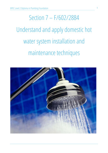
BPEC Level 2 Diploma in Plumbing Foundation12c) Systems using combination boilers5. Underfloor heating systems.1One pipe low pressure systemsOne pipe systems use a continuous loop of pipework that travels to and from the boiler. Each heat emitterwas taken from the single loop. When they were first designed, they were purely a gravity system, workingwithout the aid of a circulating pump, and there were many variations, such as the one pipe drop, one pipeladder, one pipe upfeed systems.In the late 1950s, the central heating circulating pump was developed and this greatly improved the heat-uptime of gravity systems, enabling smaller pipework to be used, typically 28mm and 22mm loops withradiators installed and connected in 15mm.In domestic dwellings, the main system used was the Pumped heating with gravity hot water (semi-gravity)system.a)Pumped heating with gravity hot water (semi-gravity)The diagram shows a typical domestic pumped one pipe semi gravity system. Here, the hot water storagecylinder heats up by gravity circulation, with the heating water to the radiators being pumped by a circulatingpump installed on the return part of the pipework loop.Each radiator is connected to the heating circuit that flows from the boiler and back to the boiler in a singleunbroken loop of pipework. The radiators are usually connected via swept tees, as shown in the diagram,The content of this document is BPEC Ltd 2020 and may not be copied, reproduced or distributed without prior written consentAuthor: BPEC Ltd. Editor: BPEC Ltd. Design: BPEC Ltd
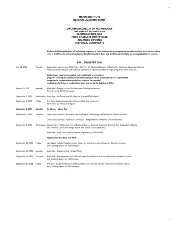
BPEC Level 2 Diploma in Plumbing Foundation13with the flow pipe connected to the top connection on the radiator. The reason for this is that although thewater in the circuit is pumped, the water is not actually pumped through the radiators. When water iscirculated mechanically, it takes the least line of resistance. Radiators offer too much resistance to flow andso the water in the radiator heats up through gravity. By installing the flow at the top of the radiator, the hotwater is circulated directly to the top section of the radiator, where it immediately begins to cool by a fewdegrees. The cooler water begins to descend through the radiator a lot more quickly than the heated waterrises through it, so the radiator heats up more rapidly than if the hot water had entered at the bottom of theradiator. This creates a better gravity circulation.A detrimental feature of this system was that each successive radiator is fed with water that is around 4 oCcooler than the previous radiator. The first radiator on the system will always be the hottest, usually around70oC, but the cooler water leaving the radiator mixes with the pipework loop, making the loop watersomewhat cooler. This cooler water is then circulated through the next radiator, leaving the radiator coolerstill and when mixed with the water in the loop, it cooled down further and so on, and so on. If we look atthe four radiators on the diagram, the first radiator will be around 70oC but the last radiator, just before theloop enters the boiler, will be considerably cooler at around 56oC. The net effect of this is that a greatersurface of heat emitter was required to heat the room. In other words, the radiators got bigger in proportionto the heat output.Thermostatic control of both the hot water and the heating within this system was solely reliant on the boilerthermostat, which often meant that the hot water in the storage cylinder was excessively hot, especially incold weather when the heating temperature was increased.2Two pipe low pressure (semi gravity) systemsTwo pipe systems were a direct development of the one pipe system and gave an immediate improvementboth in heat up times and temperature outputs of the heat emitters. Two pipe systems use two circuits; aflow circuit that goes from the boiler to every heat emitter and a return circuit that travels from every radiatorback to the boiler. The benefit of this is that every radiator, in effect, has its own circuit to and from theboiler. This ensures that all radiators achieve similar temperatures because each radiator is supplied withwater at the same temperature.aPumped heating with gravity hot water (semi-gravity)With this system, the secondary water hot water storage cylinder is heated by the heat exchanger in thecylinder. The primary flow and return are heated by the boiler and the water circulated through the coil heatexchanger by gravity circulation.The heating circuits are heated with water that is pump circulated from the boiler. The pump is installed onthe flow pipe, as this gives better flow rates through the radiators, because the hotter, less dense water iseasier to circulate through the system. A simple room thermostat helps to control the room temperaturesby switching the pump off when the thermostat is satisfied. It is used in conjunction with thermostaticradiator valves. The main disadvantage with the two pipe system is the lack of secondary hot waterThe content of this document is BPEC Ltd 2020 and may not be copied, reproduced or distributed without prior written consentAuthor: BPEC Ltd. Editor: BPEC Ltd. Design: BPEC Ltd
BPEC Level 2 Diploma in Plumbing Foundation14temperature control, as there is no thermostat fitted on to the primary flow and return. This means that thetemperature of the secondary hot water in the cylinder will be dictated by the temperature of the heatingcircuit. Look at the diagrams below:Pumped heating with gravity hot water (semi-gravity) (top) and heat sink radiator for use with a solid fuelboiler (bottom)The content of this document is BPEC Ltd 2020 and may not be copied, reproduced or distributed without prior written consentAuthor: BPEC Ltd. Editor: BPEC Ltd. Design: BPEC Ltd
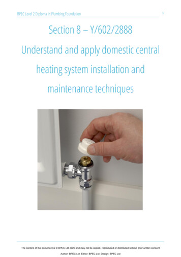
BPEC Level 2 Diploma in Plumbing Foundation15Solid fuel appliances are not as controllable as gas or oil. This makes them exceptionally difficult when itcomes to heat control because as long as there is fire in the boiler, heat will be generated. The circulation ofwater by gravity relies on the fact that heat rises and cool descends. In gravity systems this is achieved by theflow pipe being hotter than the return pipe. Where solid fuel appliances are concerned, the inability toeffectively control the heat output from the fuel means that, eventually the return pipe will be almost as hotas the flow. At this point, gravity circulation will cease and the system will boil, sometimes with disastrousconsequences. The idea of the heat leak radiator is to allow any excess heat to disperse to the surroundingatmosphere and this will ensure at least a minimum amount of continued gravity circulation through thesystem. A heat leak radiator MUST be controlled by LOCKSHIELD-TYPE radiator valves at either end of theradiator to prevent tampering.The basic layout for a system using a solid fuel boiler is very similar to other semi-gravity type systems. Thereare however, subtle differences: Solid fuel appliances use mechanical temperature control to control the heat output from the boiler.Any electrical temperature controls will need to added to the pipework. It is essential that a heat sink loop is installed with solid fuel systems and that only vented systemsare used. Sealed system components MUST NOT be installed on solid fuel heating systems.For this reason, solid fuel systems are usually fitted with the following controls: A room thermostat and a single channel time clock to control the circulating pump. A pipe thermostat installed on the gravity flow set to 45oC. The pump must not run if the temperatureis below this. The pipe thermostat prevents heat from the stored hot water in the cylinder from being‘dumped’ around the heat sink if the heat sink cools down. This is a major cause of condensation andcorrosion within the system. A second pipe thermostat, this time set to 90oC to automatically energise the pump if thetemperature exceeds 90oC to dissipate the heat through the heating system. This must be set tooverride all other controls. The system must include a heat leak circuit/radiator fitted with lockshield valves to preventtampering. An ‘anti-gravity’ valve can be included on the upstairs heating circuit to prevent unwanted gravityheating circulation, especially during the summer months. bA large capacity hot water storage vessel.C Plan (semi gravity) systemsThe Honeywell C Plan system is almost identical to the previous system. The only difference here is theinclusion of a two-port motorised zone valve on the primary flow into the cylinder. This is linked to a cylinderthermostat placed on the hot water storage cylinder about ¼ of the way up from the bottom of the cylinderto control the secondary hot water temperature. The system is now fully temperature controlled. The C Planis recognised as a possible upgrade to the two pipe (semi gravity) system for existing systems only byApproved Document L of the Building Regulations 2013 (with 2016 amendments).The content of this document is BPEC Ltd 2020 and may not be copied, reproduced or distributed without prior written consentAuthor: BPEC Ltd. Editor: BPEC Ltd. Design: BPEC Ltd
BPEC Level 2 Diploma in Plumbing Foundation16C Plan system3.Fully pumped systemsAs Domestic Heating systems developed, the need to eliminate gravity circulation became apparent. Gravitycirculation is very wasteful in terms of heat energy and fuel and so, by the inclusion of a motorised valve ora series of motorised valves, heating systems became fully pumped. In other words, the circulating pumpnow pumped the water around the heat exchanger/coil in the storage cylinder, as well as the heating systemitself. Temperature control was maintained by using a room thermostat to control the heating and a cylinderthermostat to control the secondary hot water. Three initial systems were developed:a) The Honeywell Y Plan using a three-port motorised mid-position valve,b) The Honeywell W Plan using a three-port motorised diverter valve, and;c) The Honeywell S Plan using two, two-port motorised zone valvesFully pumped systems give a greater choice of system design, especially when positioning components suchas the hot water storage cylinder. No longer was it necessary to have the cylinder higher than the boilerbecause gravity circulation had been eliminated. Other benefits are greater choice of boiler position andquicker hot water heating times. These are just a selection of the benefits of the fully pumped system.a)The Honeywell Y Plan using a three-port motorised mid-position valveThe Y Plan uses a three-port mid-position motorised valve to control the flow of water from the boiler. Thevalve reacts to the demands of the system. If both heating and hot water are needed, the valve enters a midposition allowing water to flow around both the heating and hot water circuits. If heating only is required,The content of this document is BPEC Ltd 2020 and may not be copied, reproduced or distributed without prior written consentAuthor: BPEC Ltd. Editor: BPEC Ltd. Design: BPEC Ltd
BPEC Level 2 Diploma in Plumbing Foundation17the valve swings to close off the hot water port (Port B on the valve) to allowwater to flow around the heating system only. If hot water only is required,then the valve swings to close off the heating port (Port A on the valve). Whenboth hot water and heating are satisfied, the system will shut down completelyuntil heat is required to either of the circuits and the valve returns to the midposition. Water temperatures are controlled by the room thermostat and thecylinder thermostat, with individual room temperatures controlled by3-port mid-position valvethermostatic radiator valves (TRVs). A system by-pass is fitted to allow watercirculation through the boiler to keep the boiler below its high energy cut-outtemperature (around 85oC), as this would result in the boiler overheating and the boiler ‘locking out’preventing the system from operatingThe various positions of the mid-position valveb)The Honeywell W Plan using a three-port motorised diverter valveThe W Plan system uses a three-port diverter valve. The three-port valve can either open the heating circuitThe content of this document is BPEC Ltd 2020 and may not be copied, reproduced or distributed without prior written consentAuthor: BPEC Ltd. Editor: BPEC Ltd. Design: BPEC Ltd
BPEC Level 2 Diploma in Plumbing Foundation . 5 also prefer temperatures higher than the average person. On average, 22. o. C in the winter and 23. o. C in the summer are the optimum temperatures for human comfort. Air velocity The air velocity refers to the speed at which air travels through the building. If the air is