Transcription
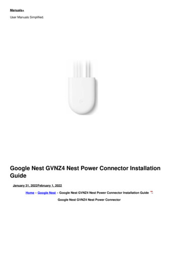
Manuals User Manuals Simplified.Google Nest GVNZ4 Nest Power Connector InstallationGuideJanuary 31, 2022February 1, 2022Home » Google Nest » Google Nest GVNZ4 Nest Power Connector Installation GuideGoogle Nest GVNZ4 Nest Power Connector
Contents [ hide123456789Safety considerationsOverviewWhat’s in the boxCompatibilityInstallation5.1 Make sure the Nest thermostat is installed5.2 If necessary, update the Nest thermostat software5.3 Turn off the power at the circuit breaker5.4 Open the HVAC equipment cover5.5 Choose the appropriate diagram from the list below and follow it to install the Nest PowerConnector5.6 Install the Nest Power Connector5.7 Close the HVAC equipment cover5.8 Confirm Nest Power Connector installation on the thermostat at g.co/nest/checkpowerconnectorOther systemsTroubleshootingQuestions?Documents / Resources9.1 Related Manuals / ResourcesSafety considerationsWarning: High voltages may be present! Be sure to turn off the power at the breaker panel orunplug the heater and/or air-conditioning unit before you begin installation or disconnect any wires.OverviewThe Nest Power Connector is a simple, easy-to-install C-wire substitute for Nest thermostats. It allows the thermostatto access power through the existing thermostat wiring without pulling new wires. And it requires only one connectionat the furnace, air handler, or zone controller.What’s in the box
Nest Power ConnectorWire connectors (2)Wire labelsSticky padInstallation guideWarrantyCompatibilitySystemsFor use with 24 VAC HVAC systems only. Not compatible with millivolt or high-voltage systems.Technical specificationsOperating temperatures: -22 to 140 F (-30 to 60 C)Voltage rating: 20 to 30 VACIngress protection: IP51ThermostatsNest Thermostat (2020)Nest Thermostat ENest Learning Thermostat (3rd gen)InstallationBefore you begin, watch the installation video at g.co/nest/powerconnectorinstall.The Nest Power Connector is installed between the thermostat wiring and the rest of the HVAC equipment.If the system has one thermostat, you’ll need to install the Nest Power Connector at the furnace or air handler.
If the system has more than one thermostat in a zoned system, you’ll need to install the Nest Power Connector at thezone controller. One Nest Power Connector is required for each Nest thermostat. At the furnace or air handler, locatethe place where the thermostat wiring connects to the HVAC equipment. This is typically at a control board, but insome systems, especially furnaces, there is no control board. In this case, the thermostat wiring joins at a series ofwire nuts (or similar). It’s sometimes necessary to remove a secondary cover inside the HVAC equipment to accessthis location.In a zone controller, locate the appropriate wiring for the thermostat the Nest Power Connector will work with.Make sure the Nest thermostat is installedIf it isn’t, follow the instructions provided with the thermostat to complete installation.If necessary, update the Nest thermostat softwareA. There’s no update needed for the Nest Thermostat E or the Nest Learning Thermostat (3rd gen). B. NestThermostat (2020) needs to run version 1.1 or later. On the device, go to Settings Version Update.Turn off the power at the circuit breakerOpen the HVAC equipment coverThe Nest Power Connector is installed or connected at the same place where all the standard thermostatconnections are normally made, at the furnace, air handler, or zone controller. See Installation on page 5 for moreinformation. Open the cover at this location and find where the Nest Power Connector should be installed.
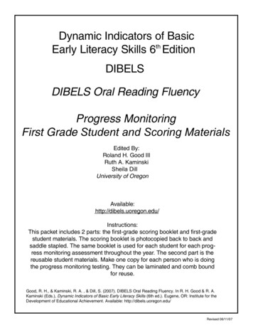
Choose the appropriate diagram from the list below and follow it to install the Nest Power ConnectorA. Heating and cooling system ›B. Cooling-only system ›C. Heating-only system ›D. If no C terminal is present in the HVAC system › Other systems ›Install the Nest Power ConnectorA. Heating and cooling systemWire the Nest Power Connector to Y.Your system may have extra wires, like a G wire (to the thermostat) and C and Y wires (to the compressor). Keepthem connected.Properly terminate any loose wires.Optional: Use the sticky pad to attach the Nest Power Connector to the panel.Installation diagramCooling and heating systemB. Cooling-only systemYour system may have extra wires, like a G wire (to the thermostat) and C and Y wires (to the compressor). Keepthem connected. Properly terminate any loose wires.
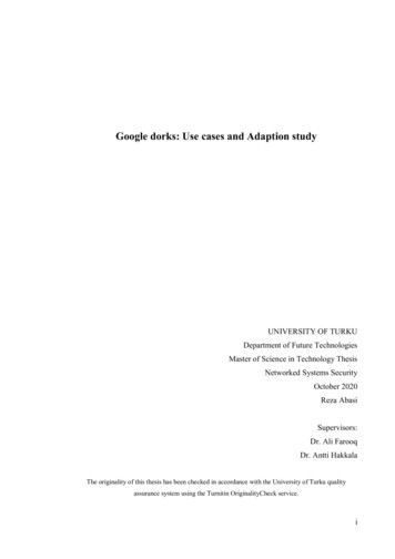
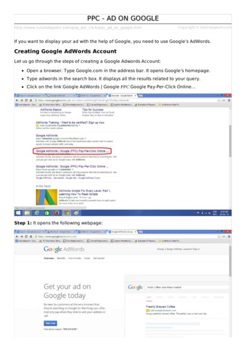
Optional: Use the sticky pad to attach the Nest Power Connector to the panel.Installation diagramCooling-only systemC. Heating-only systemYour system may have extra wires, like a G wire (to the thermostat). Keep them connected. Properly terminate anyloose wires. Optional: Use the sticky pad to attach the Nest Power Connector to the panel.Installation diagramHeating-only systemD. If no C terminal is present in the HVAC systemYou’ll need an external 24 VA/20 VA transformer and additional wire nut/lever lock connectors.1. Remove the Nest Power Connector cap.2. Remove the Nest Power Connector jumper.3. Refit the Nest Power Connector cap.Installation diagramIf no C terminal is present in the HVAC system
4. Wire external transformer C wire to the Nest Power Connector C wire.5. Wire external transformer R wire, the Nest Power Connector R wire, and thermostat R wire in a 3-way splice.6. Properly terminate any loose wires. 7. Connect the external transformer to a power source.Optional: Use the sticky pad to attach the Nest Power Connector to the panel.Installation diagramIf no C terminal is present in the HVAC systemClose the HVAC equipment coverOnce you’ve finished installing the Nest Power Connector, close the covers to the HVAC equipment, then turn on thepower. There is often a safety switch controlled by the cover that will prevent operation until it is replaced.
Confirm Nest Power Connector installation on the thermostat at g.co/nest/checkpowerconnector1. For the Nest Thermostat E and the Nest Learning Thermostat (3rd gen), no wiring or power errors are shownon the device.2. For the Nest Thermostat, go to Settings Equipment Power Connector to run a Power Test, then confirmthe status is detected in Power Info. All power errors should now be resolved.3. Make sure you can activate heating and cooling from the thermostat.Other systems“Taco” zone controllers“Taco” zone controllers are more common for hydronic multi-zone heat-only systems.1. If the thermostat terminals are labeled T&T, look for a separate connector labeled for 24 VAC and COM. COMis the C terminal connection.2. With a digital multimeter, confirm which T terminal is connected to the 24 VAC connection. Label this wire andconnection as R.3. Label the other T terminal as W. 4. Follow the heating-only diagram above.TroubleshootingNo Wi-Fi for Nest Thermostat software updateTo work with the Nest Power Connector, the Nest Thermostat will need a software update to version 1.1 or later. Thisupdate can only be made over Wi-Fi, so if the thermostat isn’t connected to Wi-Fi yet, follow the instructions from the
Google Home app to get started. You can also use a mobile hotspot to connect to the internet. The user account canbe removed from the thermostat after the software update is complete.Millivolt systemsThe Nest Power Connector and Nest thermostats are incompatible with millivolt heating systems. These systemsoften have the thermostat wiring connected to a gas valve with terminals labeled Th, Tp, and Th.To confirm that a system is millivolt, measure the voltage across the thermostat terminals/wiring while the systempower is active. A millivolt system will read 0.5 VDC. Compatible 24 VAC systems will read between 20 and 30VAC.Power errors before installationOn the Nest Thermostat, E197, N260, or N261 errors may be present before installation. These errors can beresolved by correctly installing the Nest Power Connector or a common wire.Other wires are present during installationIn some systems, particularly those with cooling, it’s common to have a second 2-wire bundle connected to thecontrol board that controls the A/C compressor. Leave these and any other attached wires in place. The Nest PowerConnector is only installed between the incoming thermostat wiring and the rest of the HVAC equipment.“No Power” errors after installation1. E298 in Nest Thermostat2. E73 or E74 in Nest Learning Thermostat (3rd gen)3. E196 in Nest Thermostat EThe thermostat is not receiving power. Confirm that the power is switched back on and that the HVAC equipmentcover is closed (there’s often a safety switch controlled by the equipment cover). Confirm the system fuses and checkand tighten all connections.“Low Power” (N260/N261) errors after installationN260/N261 in the Nest Thermostat. These errors can be resolved when the Nest Power Connector is correctlyinstalled with the thermostat. Confirm that the Nest Power Connector is installed at the correct location and to thecorrect wires. Check that all wires are connected properly.Nest Power Connector not detectedIf the Nest Power Connector is not detected by the Nest Thermostat after running a power test, go to Settings Equipment Power Connector Power Test:1. Confirm that all electrical connections were made successfully and the wiring is connected properly.2. If there’s more than one thermostat, confirm that the Nest Power Connector was installed at the zone controllerand not the HVAC equipment.On the Nest Thermostat, the Power Connector is not shown under Settings EquipmentThe Nest Thermostat may need a software update. Check for an update at Settings Version Update andconfirm the thermostat has version 1.1 or later.E297 errors on the Nest Thermostat after installationThe Nest Thermostat may need a software update. Check for an update at Settings Version Update and confirmthe thermostat has version 1.1 or later.Nest Thermostat wires not detected after installing the Nest Power ConnectorRun a Power Test on the thermostat from Settings Equipment Power Connector Power Test . Next, try toactivate the function controlled by the undetected wire(s) (for example, heating or cooling) by changing the targettemperature and thermostat mode. You can also try to run the fan from Settings.HVAC equipment terminals not labeledIdentify the wires and colors used at the thermostat for R, W, and Y and match those corresponding wires to label theterminals at the HVAC equipment.Questions?Contact our support team via phone at 855-VIP-NEST.
Documents / ResourcesGoogle Nest GVNZ4 Nest Power Connector [pdf] Installation GuideGVNZ4, Nest Power Connector, GVNZ4 Nest Power Connector, Power Connector, ConnectorRelated Manuals / ResourcesGoogle GA01317-US Nest Camera with Base User GuideLet's get started Set up your Google Nest Cam Plug your camera into anoutlet Get the Google ONR with Google Nest Wifi Singtel Setup Instruction ManualONR with Google Nest Wifi Singtel Setup Set up with ONR with GoogleNest Wifi I have a Google 385545654 Nest Cam IQ Indoor Security Camera User GuideLet’s get started Set up your Google Nest Cam Plug your camera into asocket Get the Google oxygenics POWER MAX Installation GuidePOWERMAX EASY INSTALLATION INSTRUCTIONS STEP 1 Removeyour existing shower head. To remove, turn the existing shower head Manuals ,homeprivacy
5.1 Make sure the Nest thermostat is installed 5.2 If necessary, update the Nest thermostat software 5.3 Turn off the power at the circuit breaker 5.4 Open the HVAC equipment cover 5.5 Choose the appropriate diagram from the list below and follow it to install the Nest Power Connector 5.6 Install the Nest Power Connector 5.7 Close the HVAC .