Transcription
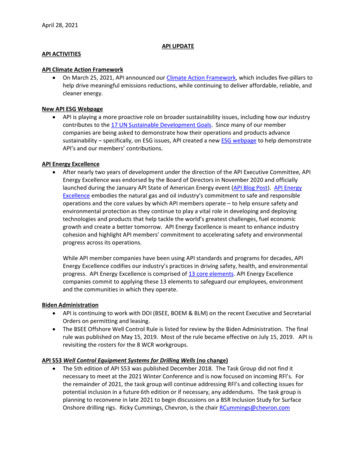
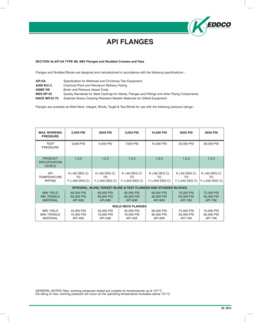
API FLANGESSECTION 4a API 6A TYPE 6B, 6BX Flanges and Studded Crosses and TeesFlanges and Studded Blocks are designed and manufactured in accordance with the following specifications:API 6AANSI B31.3ASME VIIIMSS-SP-55NACE MR-01-75Specification for Wellhead and Christmas Tree Equipment.Chemical Plant and Petroleum Refinery Piping.Boiler and Pressure Vessel Code.Quality Standards for Steel Castings for Valves, Flanges and Fittings and other Piping Components.Sulphide Stress Cracking Resistant Metallic Materials for Oilfield Equipment.Flanges are available as Weld Neck, Integral, Blinds, Target & Test Blinds for use with the following pressure ratings:-MAX. WORKINGPRESSURE2,000 PSI3000 PSI5,000 PSI10,000 PSI2000 PSI2000 PSITESTPRESSURE3,000 PSI4,500 PSI7,500 PSI15,000 PSI22,000 PSI30,000 ,2,31,2,3APITEMPERATURERATINGK (-60 DEG C)TOY ( 345 DEG C)K (-60 DEG C)TOY ( 345 DEG C)K (-60 DEG C)TOY ( 345 DEG C)K (-60 DEG C)TOY ( 345 DEG C)MIN. YIELDMN. TENSILEMATERIAL60,000 PSI85,000 PSIAPI 60K60,000 PSI85,000 PSIAPI 60KMIN. YIELDMIN. TENSILEMATERIAL45,000 PSI70,000 PSIAPI 45KWELD NECK FLANGES45,000 PSI45,000 PSI70,000 PSI70,000 PSIAPI 45KAPI 45KK (-60 DEG C)K (-60 DEG C)TOTOY ( 345 DEG C) Y ( 345 DEG C)INTEGRAL, BLIND, TARGET BLIND & TEST FLANGES AND STUDDED BLOCKS60,000 PSI85,000 PSIAPI 60K60,000 PSI85,000 PSIAPI 60K75,000 PSI95,000 PSIAPI 75K75,000 PSI95,000 PSIAPI 75K60,000 PSI85,000 PSIAPI 60K75,000 PSI95,000 PSIAPI 75K75,000 PSI95,000 PSIAPI 75KGENERAL NOTES: Max. working pressures stated are suitable for temperatures up to 121 C.De-rating of max. working pressure will occur as the operating temperature increases above 121 C.02. 2014
TYPE 6B FLANGES FOR 2000 psiRATED WORKING PRESSURETHREADED FLANGEWELD NECK LINE PIPE FLANGEMaximum Boreof Welding NeckFlangeToleranceNeck Diameter WeldingNeck Line-PipeFlangeL1L2L3 0.06AAB21/161.75—3.192.38 0.09/-0.032.102.5029 161.94—3.442.88 0.09/-0.0331 82.12—3.563.50 0.09/-0.033.1041 162.443.504.314.50 0.09/-0.034.0651 82.694.004.815.56 0.09/-0.084.8471 162.944.504.946.63 0.16/-0.035.7993.315.005.568.63 0.16/-0.037.84113.695.256.3110.75 0.16/-0.039.78135 .385.38————GENERAL NOTES: Dimensions are in inches02. 2014Hub Length WeldingNeck Line-Pipe FlangeHub LengthThreaded CasingFlangeHub LengthThreaded Line-PipeFlangeNominal Size andBore of FlangeHUB AND BORE DIMENSIONS
TYPE 6B FLANGES FOR 2000 psiRATED WORKING PRESSUREBDDCFTGAP21 162.096.50 0.060.124.251.311.003.315.00829 162.597.50 0.060.125.001.441.123.945.88831 83.228.25 0.060.125.751.561.254.626.62841 164.2810.75 0.060.126.881.811.506.008.5051 85.1613.00 0.060.128.252.061.757.44Ring number, R or RXLength of BoltsBolt Hole Tolerance(see note)Diameter of Bolt HolesDiameter of BoltsNumber of BoltsDiameter of Bolt CircleDiameter of HubBasic Thicknessof FlangeTotal Thicknessof FlangeDiameter ofRaised FaceMaximum ChamferToleranceOutside Diameter ofFlangeMaximum BoreNominal Size andBore of FlangeHUB AND BORE DIMENSIONS0.75 .064.50230.88 .065.00260.88 .065.253185 8¾¾7 81.00 .066.003710.50811.12 .066.754171 167.1614.00 0.120.259.502.191.888.7511.501211.12 .067.004599.0316.50 0.120.2511.882.502.1910.7513.751211 81.25 .068.00491111.0320.00 0.120.2514.002.812.5013.5017.00161¼1.38 .068.7553135 813.6622.00 0.120.2516.252.942.6215.7519.25201¼1.38 .069.005716¾16.7827.00 0.120.2520.003.313.0019.5023.75201½1.62 .0910.256521¼21.2832.00 0.120.2525.003.883.5024.0028.502415 81.75 .0911.7573GENERAL NOTES: Dimensions are in inches. Minimum Bolt Hole Tolerance is - 0.02 02. 2014
TYPE 6B FLANGES FOR 3000 psiRATED WORKING PRESSURETHREADED FLANGEWELD NECK LINE PIPE FLANGENeck Diameter WeldingNeck Line-PipeFlangeL2L3L4 0.06AAB—2.564.312.38 0.09/-0.031.97Hub LengthTubing FlangeL12.5629 162.81—2.814.442.88 0.09/-0.032.3531 82.44—2.944.313.50 0.09/-0.032.9341 163.063.503.504.814.50 0.09/-0.033.8651 83.444.00—5.315.56 0.09/-0.034.8471 163.694.50—5.816.63 0.016/-0.035.7994.315.00—6.698.63 0.016/-0.037.47114.565.25—7.5610.75 0.016/-0.039.34135 �20¾6.756.75—————GENERAL NOTES: Dimensions are in inches02. 2014Hub Length WeldingNeck Line-Pipe FlangeHub LengthThreaded CasingFlangeMaximum Boreof Welding NeckFlange21 16ToleranceHub LengthThreaded Line-PipeFlangeNominal Size andBore of FlangeHUB AND BORE DIMENSIONS
TYPE 6B FLANGES FOR 3000 psiRATED WORKING PRESSURERing number, R or RXBolt Hole Tolerance(see note)Diameter of Bolt HolesDiameter of BoltSNumber of BoltsDiameter of Raised FaceMaximum ChamferFTGAP0.124.881.811.504.126.5087 81.00 .066.0024Length of BoltsC 0.06Diameter of BoltCircleD8.50Diameter of HubD2.09ToleranceBMaximum BoreBasic Thicknessof Flange21 16Total Thicknessof FlangeOutside Diameter ofFlangeNominal Size andBore of FlangeHUB AND BORE DIMENSIONS29 162.599.62 0.060.125.381.941.624.887.50811.12 .066.502731 83.229.50 0.060.126.121.811.505.007.5087 81.00 .066.003141 164.2811.50 0.060.127.122.061.756.259.25811 81.25 .067.003751 85.1613.75 0.060.128.502.312.007.5011.0081¼1.38 .067.754171 67.1615.00 0.120.259.502.502.199.2512.501211 81.25 .068.004599.0318.50 0.120.2512.122.812.5011.7515.501213 81.50 .069.00491111.0321.50 0.120.2514.253.062.7514.5018.501613 81.50 .069.5053135 813.6624.00 0.120.2516.503.443.1216.5021.002013 81.50 .0610.255716¾16.7827.75 0.120.2520.623.943.5020.0024.252015 81.75 .0911.756620¾20.7833.75 0.120.2525.504.754.2524.5029.502022.12 .0914.5074GENERAL NOTES: Dimensions are in inches. Minimum Bolt Hole Tolerance is - 0.02 02. 2014
TYPE 6B FLANGES FOR 5000 psiRATED WORKING PRESSURETHREADED FLANGEWELD NECK LINE PIPE FLANGE21 16Maximum Boreof Welding NeckFlangeToleranceNeck Diameter WeldingNeck Line-PipeFlangeHub Length WeldingNeck Line-Pipe FlangeL1L2L3L4 0.06AAB2.56—2.564.312.38 0.09/-0.031.7229 162.81—2.814.442.88 0.09/-0.032.1631 83.19—3.194.943.50 0.09/-0.032.6541 163.883.883.885.194.50 0.09/-0.033.4751 84.444.44—6.445.56 0.09/-0.034.3471 165.065.06—7.136.63 0.016/-0.035.2296.066.06—8.818.63 0.016/-0.036.84116.696.69—10.4410.75 0.016/-0.038.53GENERAL NOTES: Dimensions are in inches02. 2014Hub LengthTubing FlangeHub LengthThreaded CasingFlangeHub LengthThreaded Line-PipeFlangeNominal Size andBore of FlangeHUB AND BORE DIMENSIONS
TYPE 6B FLANGES FOR 5000 psiRATED WORKING PRESSURERing number, R or RXBolt Hole Tolerance(see note)Diameter of Bolt HolesDiameter of BoltSFTGAP0.124.881.811.504.126.50829 162.599.62 0.060.125.381.941.624.887.50811.12 .066.502731 83.2210.50 0.060.126.622.191.885.258.00811 81.25 .067.25357 81.00 .06Length of BoltsC 0.06Diameter of BoltCircleD8.50Diameter of HubBasic Thicknessof FlangeD2.09ToleranceB21 16Maximum BoreTotal Thicknessof FlangeNumber of BoltsDiameter of Raised FaceMaximum ChamferOutside Diameter ofFlangeNominal Size andBore of FlangeHUB AND BORE DIMENSIONS6.002441 164.2812.25 0.060.127.622.442.126.389.5081¼1.38 .068.003951 85.1614.75 0.060.129.003.192.887.7511.5081½1.62 .0610.004471 167.1615.50 0.120.259.753.623.259.0012.501213 81.50 .0610.754699.0319.00 0.120.2512.504.063.6211.5015.501215 81.75 .0912.00501111.0323.00 0.120.2514.634.694.2514.5019.001217 82.00 .0913.7554GENERAL NOTES: Dimensions are in inches. Minimum Bolt Hole Tolerance is - 0.02 02. 2014
TYPE 6BX INTEGRAL FLANGES FOR 2000, 3000, and 5000 psiRATED WORKING PRESSUREBDDCFTAELRPRing numberMinimum Lengthof Stud BoltsBolt Hole Tolerance (see note)Diameter of Bolt HolesDiameter of BoltsNumber of BoltsDiameter of Bolt CircleRadius of HubLength of HubSmall Diameter of HubLarge Diameter of HubTotal Thickness of FlangeDiameter of Raised FaceMaximum ChamferToleranceOutside Diameter ofFlangeMaximum BoreNominal Size andBore of FlangeHUB AND FLANGE DIMENSIONSBX2000 psi26¾26.7841.00 0.120.2531.694.9732.9129.257.310.6237.50201¾1.88 .0913.753030.0344.19 0.120.2535.755.2836.6932.807.750.6240.943215 81.75 .0914.25 3 031673000 psi26¾26.7843.38 0.120.2532.756.3434.2530.567.310.6239.382422.12 .0917.001683030.0346.68 0.120.2536.316.5838.1934.307.750.6242.943217 82.00 .0917.753035000 psi133 813.6626.50 0.120.2518.004.4418.9416.694.500.6223.251615 81.75 .0912.5016016¾16.7830.38 0.120.2521.065.1321.8820.753.000.7526.621617 82.00 .0914.5016218¾18.7835.62 0.120.2524.696.5326.5623.566.000.6231.622022.12 .0917.5016321¼21.28 39.00 0.120.2527.627.1229.8826.756.500.6934.882422.12 .0918.75165GENERAL NOTES: Dimensions are in inches. Minimum Bolt Hole Tolerance is -0.0202. 2014
TYPE 6BX INTEGRAL FLANGES FOR10 000 psi RATED WORKING PRESSURETAEBolt Hole Tolerance (see note)Ring numberBXMinimum Lengthof Stud BoltsPDiameter of Bolt HolesRDiameter of BoltsLNumber of BoltsSmall Diameter of HubLarge Diameter of HubTotal Thickness of FlangeDiameter of Raised FaceFDiameter of Bolt CircleCRadius of HubDLength of HubDMaximum ChamferBToleranceMaximum BoreOutside Diameter ofFlangeNominal Size andBore of FlangeHUB AND FLANGE DIMENSIONS10 000 psi113 161.847.38 0.060.124.121.663.502.561.910.385.758¾0.88 .065.0015121 162.097.88 0.060.124.381.733.942.942.030.386.258¾0.88 .065.2015229 162.599.12 0.060.125.192.024.753.622.250.387.2587 81.00 .066.0015331 163.0910.62 0.060.126.002.305.594.342.500.388.50811.12 .066.7515441 164.0912.44 0.060.127.282.777.195.752.880.3810.19811 81.25 .068.0015551 85.1614.06 0.060.128.693.128.817.193.190.3811.811211 81.25 .068.7516971 167.0918.88 0.120.2511.884.0611.8810.003.750.6215.88121½1.62 .0911.2515699.0321.75 0.120.2514.124.8814.7512.883.690.6218.75161½1.62 .0913.001571111.0325.75 0.120.2516.885.5617.7515.754.060.6222.25161¾1.88 .0915.00158135 813.6630.25 0.120.2520.386.6221.7519.504.500.6226.502017 82.00 .0917.2515916¾16.7834.31 0.120.2522.696.6225.8123.693.000.7530.562417 82.00 .0917.5016218¾18.7840.94 0.120.2527.448.7829.6226.566.120.6236.44242¼2.38 .0922.5016421¼21.2845.00 0.120.2530.759.5033.3830.006.500.8140.25242½2.62 .0924.50166GENERAL NOTES: Dimensions are in inches. Minimum Bolt Hole Tolerance is - 0.02 02. 2014
TYPE 6BX INTEGRAL FLANGES FOR 15 000 psiRATED WORKING PRESSUREEBolt Hole Tolerance (see note)BXRing numberPMinimum Lengthof Stud BoltsRDiameter of Bolt HolesLDiameter of BoltsANumber of BoltsTDiameter of Bolt CircleFRadius of HubLarge Diameter of HubCLength of HubTotal Thickness of FlangeDSmall Diameter of HubDiameter of Raised FaceDMaximum ChamferBToleranceMaximum BoreOutside Diameter ofFlangeNominal Size andBore of FlangeHUB AND FLANGE DIMENSIONS15 000 psi113 161.848.19 0.060.124.191.783.842.811.880.386.3187 81.00 .065.5015121 162.098.75 0.060.124.502.004.383.252.120.386.8887 81.00 .066.0015229 162.5910.00 0.060.125.252.255.063.942.250.387.88811.12 .066.7515331 163.0911.31 0.060.126.062.536.064.812.500.389.06811 81.25 .067.5015441 164.0914.19 0.060.127.623.097.696.252.880.3811.44813 81.50 .069.2515551 85.1616.50 0.060.128.883.889.627.883.220.6213.50121½1.62 .0911.5016971 167.0919.88 0.120.2512.004.6912.8110.882.620.6216.88161½1.62 .0912.7515699.0325.50 0.120.2515.005.7517.0013.754.880.6221.751617 82.00 .0915.751571111.0332.00 0.120.2517.887.3823.0016.819.280.6228.002022.12 .0919.25158135 813.6634.88 0.120.2521.318.0623.4420.814.501.0030.38202¼2.38 .0921.2515918¾18.7845.75 0.120.2528.4410.0632.0028.756.121.0040.002033.12 .1226.75164GENERAL NOTES: Dimensions are in inches. Minimum Bolt Hole Tolerance is - 0.02 02. 2014
TYPE 6BX INTEGRAL FLANGES FOR20 000 psi RATED WORKING PRESSUREDCFTAEMinimum Lengthof Stud BoltsBolt Hole Tolerance (see note)Diameter of Bolt HolesDiameter of BoltsNumber of BoltsDiameter of Bolt CircleLRPBX151Ring numberSmall Diameter of HubLarge Diameter of HubTotal Thickness of FlangeDiameter of Raised FaceMaximum ChamferToleranceOutside Diameter ofFlangeDRadius of HubBLength of HubMaximum BoreNominal Size andBore of FlangeHUB AND FLANGE DIMENSIONS20 000 psi113 161.8410.12 0.060.124.622.505.254.311.940.388.008121 162.0911.31 0.060.125.192.816.065.002.060.389.06811 81.25 .068.2515229 162.5912.81 0.060.125.943.126.815.692.310.3810.3181¼1.38 .069.251531.12 .067.5031 163.0914.06 0.060.126.753.387.566.312.500.3811.31813 81.50 .0610.0015441 164.0917.56 0.060.128.624.199.568.122.880.3814.0681¾1.88 .0912.2515571 167.0925.81 0.120.2513.886.5015.1913.313.810.6221.811622.12 .0917.5015699.0331.69 0.120.2517.388.0618.9416.884.251.0027.00162½2.62 .0922.381571111.0334.75 0.120.2519.888.8122.3120.004.061.0029.50162¾2.88 .0923.75158135 813.6645.75 0.120.2524.1911.5027.3124.755.251.0040.002033.12 .1230.00159GENERAL NOTES: Dimensions are in inches. Minimum Bolt Hole Tolerance is - 0.02 02. 2014
TYPE 6BX WELDING NECK FLANGES FOR 10 000 psiRATED WORKING PRESSUREDCFTAERPRing numberMinimum Lengthof Stud BoltsBolt Hole Tolerance (see note)Diameter of Bolt HolesLBX10 000 psi113 161.847.38 0.060.124.121.663.502.561.910.385.75821 162.097.88 0.060.124.381.733.942.942.030.386.25829 162.599.12 0.060.125.192.024.753.622.250.387.25831 163.0910.62 0.060.126.002.305.594.342.500.388.50841 164.0912.44 0.060.127.282.777.195.752.880.3810.19851 85.1614.06 0.060.128.693.138.817.193.190.3811.811271 167.0918.88 75 5.75 0.120.2516.885.5617.7515.754.060.6222.2516135 813.6630.25 834.31 0.120.2522.696.6225.8123.693.000.7530.5624GENERAL NOTES: Dimensions are in inches. Minimum Bolt Hole Tolerance is - 0.02 Available with a transition from 4130 to LF202. 2014Diameter of BoltsNumber of BoltsDiameter of Bolt CircleSmall Diameter of HubLarge Diameter of HubTotal Thickness of FlangeDiameter of Raised FaceMaximum ChamferToleranceOutside Diameter ofFlangeDRadius of HubBLength of HubMaximum BoreNominal Size andBore of FlangeHUB AND FLANGE DIMENSIONS¾¾7 8111 811 81½1½1¾17 817 8.88 .065.00151.88 .065.251521.00 .066.001531.12 .066.751541.25 .068.001551.25 .068.751691.62 .0911.251561.62 .0913.001571.88 .0915.001582.00 .0917.251592.00 .0917.50162
TYPE 6BX WELDING NECK FLANGES FOR15 000 and 20 000 psi RATED WORKING PRESSUREDCFTAELRPRing numberMinimum Lengthof Stud BoltsBolt Hole Tolerance (se
API 6A Specification for Wellhead and Christmas Tree Equipment. ANSI B31.3 Chemical Plant and Petroleum Refinery Piping. ASME VIII Boiler and Pressure Vessel Code. MSS-SP-55 Quality Standards for Steel Castings for Valves, Flanges and Fittings and other Piping Components. NACE MR-01-75 Sulphide Stress Cracking Resistant Metallic Materials for Oilfield Equipment. Flanges are available as
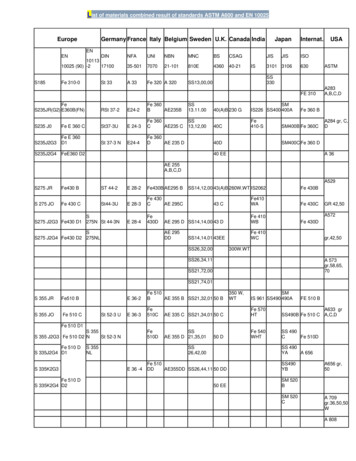
![API Ballot: [Ballot ID] – API 510 & API 570, Deferrals, Rev05](/img/5/api510andapi570deferralsrev5.jpg)