Transcription
CCNP SWITCH 6.0Student Lab ManualThis document is exclusive property of Cisco Systems, Inc. Permission is grantedto print and copy this document for non-commercial distribution and exclusiveuse by instructors in the CCNP TSHOOT course as part of an official CiscoNetworking Academy Program.
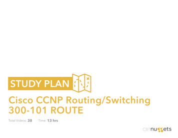
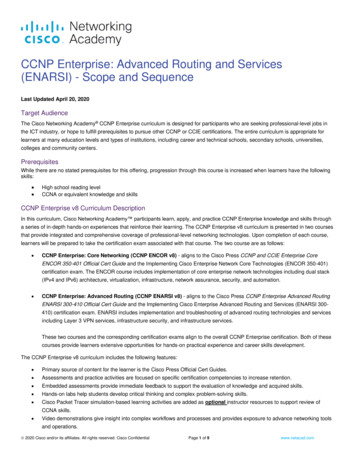
CCNPv6 SWITCHChapter 1 Lab 1-1, Clearing a SwitchTopologyObjective Clear the configuration of a standalone switch to prepare it for a new lab.BackgroundWhen working with a switch that has been previously configured, any new commands entered will be mergedwith the existing configuration, causing unpredictable results. In this lab you prepare a Catalyst 2960 or 3560switch for use with a lab. This is accomplished by erasing the startup configuration from NVRAM and deletingthe VLAN database.Note: This lab uses the Cisco WS-C2960-24TT-L switch with the Cisco IOS image c2960-lanbasek9-mz.12246.SE.bin and the Catalyst 3560-24PS switch with the Cisco IOS image c3560-advipservicesk9-mz.12246.SE.bin. Other switches (such as a 2950 or a 3550), and Cisco IOS Software versions can be used if theyhave comparable capabilities and features. Depending on the switch model and Cisco IOS Software version,the commands available and output produced might vary from what is shown in this lab.Required ResourcesYou may use one of the following switches or a comparable one with this lab: Cisco 2960 with the Cisco IOS Release 12.2(46)SE C2960-LANBASEK9-M image or comparable Cisco 3560 with the Cisco IOS Release 12.2(46)SE C3560-ADVIPSERVICESK9-M image orcomparable Console cableAll contents are Copyright 1992–2010 Cisco Systems, Inc. All rights reserved. This document is Cisco Public Information.Page 1 of 5
CCNPv6 SWITCHStep 1: Connect to the switch console port and enter privileged EXEC mode.From a computer running a terminal emulation program, connect to the console port of the switch that youwant to clear using a console cable. You should see a console prompt that includes the switch’s hostname,followed by a or #. The default switch hostname is “Switch.”Switch orSwitch#If the prompt ends with a , you are not in privileged EXEC mode. To enter privileged EXEC mode, typeenable. This might require a password. If you are in a configuration mode, type exit or end.If not enabled:Switch enableSwitch#If in global configuration mode:Switch(config)# exitSwitch#Step 2: Delete the VLAN database file.In privileged EXEC mode, type delete flash:vlan.dat and press Enter. If you are asked to confirm, pressEnter until you are back to the original prompt.Switch# delete flash:vlan.datDelete flash:vlan.dat? [confirm]Switch#Step 3: Erase the startup config from NVRAM.After deleting the vlan.dat file, you can erase the startup configuration on the switch by typing erase startupconfig. You again have to press Enter to confirm.Switch# erase startup-configErasing the nvram filesystem will remove all configuration files! Continue?[confirm][OK]Erase of nvram: completeSwitch#Step 4: Reload the device, but do not save the system configuration if prompted.After clearing the switch configuration, reload the switch by typing reload and pressing Enter. If you are askedwhether to save the current configuration, answer no. Press Enter to confirm. The switch starts reloading.Your output might look different depending on the switch model that you are using. This step might take a fewminutes, because the switch needs time to reload.Switch# reloadSystem configuration has been modified. Save? [yes/no]: noProceed with reload? [confirm]%SYS-5-RELOAD: Reload requested by console. Reload Reason: Reload command.Base ethernet MAC Address: 00:1b:0c:6d:8f:00Xmodem file system is available.The password-recovery mechanism is enabled.All contents are Copyright 1992–2010 Cisco Systems, Inc. All rights reserved. This document is Cisco Public Information.Page 2 of 5
CCNPv6 SWITCHInitializing Flash.flashfs[0]: 606 files, 20 directoriesflashfs[0]: 0 orphaned files, 0 orphaned directoriesflashfs[0]: Total bytes: 32514048flashfs[0]: Bytes used: 10336256flashfs[0]: Bytes available: 22177792flashfs[0]: flashfs fsck took 10 seconds.done Initializing Flash.Boot Sector Filesystem (bs) installed, fsid: 3done.Loading @@@@@@@@@@@@@@@@@@@@@@@@@@@@@@@@@@@@@File -mz.122-46.SE.bin" uncompressed and installed, entry point: 0x3000executing.Restricted Rights LegendUse, duplication, or disclosure by the Government issubject to restrictions as set forth in subparagraph(c) of the Commercial Computer Software - RestrictedRights clause at FAR sec. 52.227-19 and subparagraph(c) (1) (ii) of the Rights in Technical Data and ComputerSoftware clause at DFARS sec. 252.227-7013.cisco Systems, Inc.170 West Tasman DriveSan Jose, California 95134-1706Cisco IOS Software, C2960 Software (C2960-LANBASEK9-M), Version 12.2(46)SE, RELEASE SOFTWARE (fc2)Copyright (c) 1986-2008 by Cisco Systems, Inc.Compiled Thu 21-Aug-08 15:59 by nachenImage text-base: 0x00003000, data-base: 0x01200000All contents are Copyright 1992–2010 Cisco Systems, Inc. All rights reserved. This document is Cisco Public Information.Page 3 of 5
CCNPv6 SWITCHInitializing ]:flashfs[1]:flashfs[1]:flashfs[1]:606 files, 20 directories0 orphaned files, 0 orphaned directoriesTotal bytes: 32514048Bytes used: 10336256Bytes available: 22177792flashfs fsck took 1 seconds.Initialization complete.done Initializing flashfs.POST: CPU MIC register Tests : BeginPOST: CPU MIC register Tests : End, Status PassedPOST: PortASIC Memory Tests : BeginPOST: PortASIC Memory Tests : End, Status PassedPOST: CPU MIC interface Loopback Tests : BeginPOST: CPU MIC interface Loopback Tests : End, Status PassedPOST: PortASIC RingLoopback Tests : BeginPOST: PortASIC RingLoopback Tests : End, Status PassedPOST: PortASIC CAM Subsystem Tests : BeginPOST: PortASIC CAM Subsystem Tests : End, Status PassedPOST: PortASIC Port Loopback Tests : BeginPOST: PortASIC Port Loopback Tests : End, Status PassedWaiting for Port download.CompleteThis product contains cryptographic features and is subject to UnitedStates and local country laws governing import, export, transfer anduse. Delivery of Cisco cryptographic products does not implythird-party authority to import, export, distribute or use encryption.Importers, exporters, distributors and users are responsible forcompliance with U.S. and local country laws. By using this product youagree to comply with applicable laws and regulations. If you are unableto comply with U.S. and local laws, return this product immediately.A summary of U.S. laws governing Cisco cryptographic products may be found rg.htmlIf you require further assistance please contact us by sending email toexport@cisco.com.cisco WS-C2960-24TT-L (PowerPC405) processor (revision B0) with 61440K/4088K bytes of memory.Processor board ID FOC1104W0G0Last reset from power-on1 Virtual Ethernet interface24 FastEthernet interfaces2 Gigabit Ethernet interfacesThe password-recovery mechanism is enabled.64K bytes of flash-simulated non-volatile configuration memory.Base ethernet MAC Address: 00:1B:0C:6D:8F:00All contents are Copyright 1992–2010 Cisco Systems, Inc. All rights reserved. This document is Cisco Public Information.Page 4 of 5
CCNPv6 SWITCHMotherboard assembly numberPower supply part numberMotherboard serial numberPower supply serial numberModel revision numberMotherboard revision numberModel numberSystem serial numberTop Assembly Part NumberTop Assembly Revision NumberVersion IDCLEI Code NumberHardware Board Revision 21-02C0V02COM3L00BRA0x01Switch Ports Model------ ----- ----*1 26WS-C2960-24TT-LSW Version---------12.2(46)SESW Image---------C2960-LANBASEK9-MStep 5: When the switch restarts, do not enter the initial configuration dialog, butterminate autoinstall.The switch might log messages to the console, such as interfaces coming up and down. When you see the“Press RETURN to get started!” prompt, press Enter.If you are asked to enter an initial configuration dialog, type no. This places you at the user EXEC prompt. Ifyou accidentally type yes, you can break out of the initial configuration dialog at any time by pressing Ctrl-C. Ifyou are asked whether you want to terminate autoinstall, press Enter for “yes.”Press RETURN to get started! Enter--- System Configuration Dialog --Would you like to enter the initial configuration dialog? [yes/no]: noWould you like to terminate autoinstall? [yes]: EnterAll contents are Copyright 1992–2010 Cisco Systems, Inc. All rights reserved. This document is Cisco Public Information.Page 5 of 5
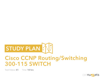
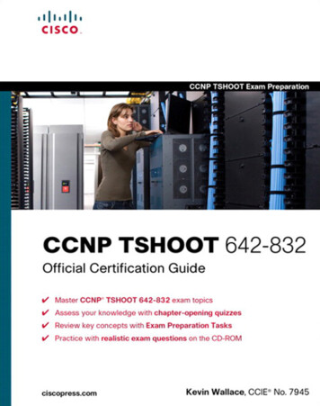
CCNPv6 SWITCHChapter 1 Lab 1-2, Clearing a Switch Connected to a Larger NetworkTopologyObjective Clear the configuration of a switch that is connected to other switches and prepare it for a new lab.BackgroundWhen working with a switch that has been previously configured, any new commands entered are mergedwith the existing configuration, causing unpredictable results. Additionally, if the switch is connected to otherswitches in the network, you can remove the VLANs but they might be relearned from another switch via VTP.In this lab, you prepare a Catalyst 2960 or 3560 switch for use with a lab by erasing the startup configurationfrom NVRAM and deleting the VLAN database. You also ensure that VLANs will not be relearned fromanother switch after the VLAN database has been deleted.Note: This lab uses the Cisco WS-C2960-24TT-L switch with the Cisco IOS image c2960-lanbasek9-mz.12246.SE.bin, and the Catalyst 3560-24PS switch with the Cisco IOS image c3560-advipservicesk9-mz.12246.SE.bin. You can use other switches (such as a 2950 or a 3550) and Cisco IOS Software versions if theyhave comparable capabilities and features. Depending on the switch model and Cisco IOS Software version,the commands available and output produced might vary from what is shown in this lab.Required Resources 2 switches (Cisco 2960 with the Cisco IOS Release 12.2(46)SE C2960-LANBASEK9-M image orcomparable) 2 switches (Cisco 3560 with the Cisco IOS Release 12.2(46)SE C3560-ADVIPSERVICESK9-Mimage or comparable)All contents are Copyright 1992–2010 Cisco Systems, Inc. All rights reserved. This document is Cisco Public Information.Page 1 of 4
CCNPv6 SWITCH Console and Ethernet cablesStep 1: Connect to the switch console port and enter privileged EXEC mode.This lab assumes that you have completed Lab 1-1, Clearing a Switch.Step 2: Delete the VLAN database file.In privileged EXEC mode, type delete vlan.dat and press Enter. If you are asked to confirm, press Enteruntil you are back to the original prompt.Switch# delete vlan.datDelete flash:vlan.dat? [confirm]Switch#Step 3: Erase the startup config from NVRAM.After deleting the vlan.dat file, you can erase the startup configuration on the switch by typing erasestartup-config. You again have to press Enter to confirm. Reload the switch.Switch# erase startup-configErasing the nvram filesystem will remove all configuration files! Continue?[confirm][OK]Erase of nvram: completeSwitch#Switch# reloadStep 4: Display the existing configured VLANs.The difficulty with clearing a switch that is cabled to other switches is removing the VLANs. When the switchis finished reloading, it is possible for it to relearn VLANs from another connected switch that is in VTP serveror client mode.To determine if the VLANs have been relearned, use the show vlan command.Switch# show vlan briefVLAN NameStatusPorts---- -------------------------------- --------- ------------------------------1defaultactiveFa0/1, Fa0/2, Fa0/3, Fa0/4Fa0/5, Fa0/6, Fa0/7, Fa0/8Fa0/9, Fa0/10, Fa0/11, Fa0/12Fa0/13, Fa0/14, Fa0/15, Fa0/16Fa0/17, Fa0/18, Fa0/19, Fa0/20Fa0/21, Fa0/22, Fa0/23, Fa0/24Gi0/1, Gi0/21002 fddi-defaultact/unsup1003 token-ring-defaultact/unsup1004 fddinet-defaultact/unsup1005 trnet-defaultact/unsupIn this sample output, the switch has not learned any VLANs from another switch. You are finished clearingboth the configuration and VLANs from the switch.However, if the show vlan command displays nondefault VLANs after you have deleted the vlan.dat file,your switch has learned the VLANs dynamically from another switch. For example:Switch# show vlan briefAll contents are Copyright 1992–2010 Cisco Systems, Inc. All rights reserved. This document is Cisco Public Information.Page 2 of 4
CCNPv6 SWITCHVLAN NameStatusPorts---- -------------------------------- --------- ------------------------------1defaultactiveFa0/1, Fa0/2, Fa0/3, Fa0/4Fa0/5, Fa0/6, Fa0/7, Fa0/8Fa0/9, Fa0/10, Fa0/11, Fa0/12Fa0/13, Fa0/14, Fa0/15, Fa0/16Fa0/17, Fa0/18, Fa0/19, Fa0/20Fa0/21, Fa0/22, Fa0/23, Fa0/24Gi0/1, VERSactive100 MGMTactive200 TRANSactive900 NATIVEactive999 nsupact/unsupact/unsupStep 5: Shut down interfaces and remove the VLANs.To eliminate these VLANS, shut down all interfaces and remove the existing VLANs.Switch(config)# interface range FastEthernet 0/1 - 24Switch(config-if-range)# shutdownSwitch(config-if-range)#15:44:06: %LINK-5-CHANGED: Interface FastEthernet0/1,administratively down15:44:06: %LINK-5-CHANGED: Interface FastEthernet0/2,administratively down15:44:06: %LINK-5-CHANGED: Interface FastEthernet0/3,administratively down15:44:06: %LINK-5-CHANGED: Interface FastEthernet0/4,administratively down15:44:06: %LINK-5-CHANGED: Interface FastEthernet0/5,administratively down15:44:06: %LINK-5-CHANGED: Interface FastEthernet0/6,administratively down output omitted changed state tochanged state tochanged state tochanged state tochanged state tochanged state toSwitch(config-if-range)# interface range GigabitEthernet 0/1 - 2Switch(config-if-range)# shutdownSwitch(config-if-range)#15:45:59: %LINK-5-CHANGED: Interface GigabitEthernet0/1, changed state toadministratively down15:45:59: %LINK-5-CHANGED: Interface GigabitEthernet0/2, changed state toadministratively downSwitch(config-if-range)# exitSwitch(config)# no vlan 2-999Switch(config)#exitAll contents are Copyright 1992–2010 Cisco Systems, Inc. All rights reserved. This document is Cisco Public Information.Page 3 of 4
CCNPv6 SWITCHSwitch# show vlan briefVLAN NameStatusPorts---- -------------------------------- --------- ------------------------------1defaultactiveFa0/1, Fa0/2, Fa0/3, Fa0/4Fa0/5, Fa0/6, Fa0/7, Fa0/8Fa0/9, Fa0/10, Fa0/11, Fa0/12Fa0/13, Fa0/14, Fa0/15, Fa0/16Fa0/17, Fa0/18, Fa0/19, Fa0/20Fa0/21, Fa0/22, Fa0/23, Fa0/24Gi0/1, Gi0/21002 fddi-defaultact/unsup1003 token-ring-defaultact/unsup1004 fddinet-defaultact/unsup1005 trnet-defaultact/unsupStep 6: (Optional) Configure transparent VTP mode.Now that both the startup configuration and the VLANs have been erased, you are ready to start a new lab.For interfaces that need to be up, use the no shutdown command in the new lab. If you want to do someconfiguration before the switch learns VLANs from the network, put it into VTP transparent mode until you areready.Switch# conf tEnter configuration commands, one per line.Switch(config)# vtp mode transparentSetting device to VTP TRANSPARENT mode.End with CNTL/Z.All contents are Copyright 1992–2010 Cisco Systems, Inc. All rights reserved. This document is Cisco Public Information.Page 4 of 4
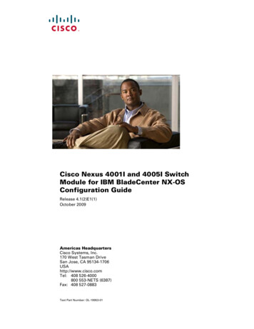
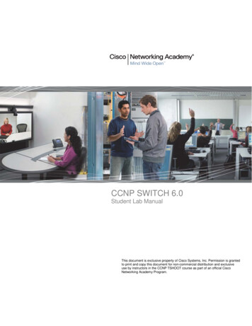
CCNPv6 SWITCHChapter 2 Lab 2-1, Static VLANS, VLAN Trunking, and VTP Domainsand ModesTopologyObjectives Set up a VTP domain. Create and maintain VLANs. Configure ISL and 802.1Q trunking.BackgroundVLANs logically segment a network by function, team, or application, regardless of the physical location of theusers. End stations in a particular IP subnet are often associated with a specific VLAN. VLAN membership ona switch that is assigned manually for each interface is known as static VLAN membership.Trunking, or connecting switches, and the VLAN Trunking Protocol (VTP) are technologies that supportVLANs. VTP manages the addition, deletion, and renaming of VLANs on the entire network from a singlecentral switch.Note: This lab uses Cisco WS-C2960-24TT-L switches with the Cisco IOS image c2960-lanbasek9-mz.12246.SE.bin, and Catalyst 3560-24PS with the Cisco IOS image c3560-advipservicesk9-mz.122-46.SE.bin. Youcan use other switches (such as a 2950 or 3550) and Cisco IOS Software versions if they have comparablecapabilities and features. Depending on the switch model and Cisco IOS Software version, the commandsavailable and output produced might vary from what is shown in this lab.All contents are Copyright 1992–2010 Cisco Systems, Inc. All rights reserved. This document is Cisco Public Information.Page 1 of 16
CCNPv6 SWITCHRequired Resources 2 switches (Cisco 2960 with the Cisco IOS Release 12.2(46)SE C2960-LANBASEK9-M image orcomparable) 2 switches (Cisco 3560 with the Cisco IOS Release 12.2(46)SE C3560-ADVIPSERVICESK9-Mimage or comparable) 4 PCs (optional) Ethernet and console cablesStep 1: Prepare the switches for the lab.Power up the switches and use the standard process for establishing a HyperTerminal console connectionfrom a workstation to each switch in your pod. If you are connecting remotely to the switches, follow theinstructions that have been supplied by your instructor.Remove all VLAN information and configurations that may have been previously entered into the switches.Refer to Lab 1-1, “Clearing a Switch,” and Lab 1-2, “Clearing a Switch Connected to a Larger Network.”Step 2: Configure basic switch parameters.Assign each switch a hostname and configure an IP address on the management VLAN according to thediagram. By default, VLAN 1 is used as the management VLAN.Enter basic configuration commands on each switch according to the diagram.DLS1 example:Switch# configure terminalEnter configuration commands, one per line. End with CNTL/Z.Switch(config)# hostname DLS1DLS1(config)# interface vlan 1DLS1(config-if)# ip address 10.1.1.101 255.255.255.0DLS1(config-if)# no shutdown(Optional) On each switch, create an enable secret password and configure the vty lines to allow remoteaccess from other network devices.DLS1 example:DLS1(config)# enable secret ciscoDLS1(config)# line vty 0 15DLS1(config-line)# password ciscoDLS1(config-line)# loginStep 3: Display the switch default VLAN information.Use the show vlan command in privileged mode on any switch. The following output is for a 2960 switch.ALS1# show vlanVLAN NameStatusPorts---- -------------------------------- --------- ------------------------------1defaultactiveFa0/1, Fa0/2, Fa0/3, Fa0/4Fa0/5, Fa0/6, Fa0/7, Fa0/8Fa0/9, Fa0/10, Fa0/11, Fa0/12Fa0/13, Fa0/14, Fa0/15, Fa0/16Fa0/17, Fa0/18, Fa0/19, Fa0/20Fa0/21, Fa0/22, Fa0/23, Fa0/24Gi0/1, Gi0/2All contents are Copyright 1992–2010 Cisco Systems, Inc. All rights reserved. This document is Cisco Public Information.Page 2 of 16
CCNPv6 -------Trans1-----00000Trans2-----00000Remote SPAN ---------------------------------Primary Secondary TypePorts------- --------- ----------------- -----------------------------------------The following output is for a 3560 switch.DLS1# show vlanVLAN NameStatusPorts---- -------------------------------- --------- ------------------------------1defaultactiveFa0/1, Fa0/2, Fa0/3, Fa0/4Fa0/5, Fa0/6, Fa0/7, Fa0/8Fa0/9, Fa0/10, Fa0/11, Fa0/12Fa0/13, Fa0/14, Fa0/15, Fa0/16Fa0/17, Fa0/18, Fa0/19, Fa0/20Fa0/21, Fa0/22, Fa0/23, Fa0/24Gi0/1, Gi0/21002 fddi-defaultact/unsup1003 token-ring-defaultact/unsup1004 fddinet-defaultact/unsup1005 e SPAN ---------------------------------Primary Secondary TypePorts------- --------- ----------------- -----------------------------------------Note the default VLAN numbers, names, and associated types, and that all switch ports are automaticallyassigned to VLAN 1.All contents are Copyright 1992–2010 Cisco Systems, Inc. All rights reserved. This document is Cisco Public Information.Page 3 of 16
CCNPv6 SWITCHYou can use the show vlan command to determine the mode of a port. Ports configured for a particularVLAN are shown in that VLAN. Ports configured for trunk mode are not associated with a specific VLAN, andso are not included in the output.Step 4: Examine VTP information.A VTP domain, also called a VLAN management domain, consists of trunked switches that are under theadministrative responsibility of a switch or switches in server VTP mode. A switch can be in only one VTPdomain with the same VTP domain name. The default VTP mode for the 2960 and 3560 switches is servermode. VLAN information is not propagated until a domain name is specified and trunks are set up betweenthe devices.The following table describes the three VTP modes.VTP ModeVTP serverDescriptionYou can create, modify, and delete VLANs and specify otherconfiguration parameters, such as VTP version and VTPpruning, for the entire VTP domain. VTP servers advertise theirVLAN configuration to other switches in the same VTP domainand synchronize their VLAN configuration with other switchesbased on advertisements received over trunk links.VTP server is the default mode.VTP clientVTP clients behave the same way as VTP servers, but youcannot create, change, or delete VLANs on a VTP client.VTP transparentVTP transparent switches do not participate in VTP. A VTPtransparent switch does not advertise its VLAN configuration norsynchronize its VLAN configuration based on receivedadvertisements. Transparent switches do forward VTPadvertisements that they receive out their trunk ports in VTPVersion 2.Use the show vtp status command on any switch. The output should be similar to the following sample forDLS1.DLS1# show vtp statusVTP Version: running VTP1 (VTP2 capable)Configuration Revision: 0Maximum VLANs supported locally : 1005Number of existing VLANs: 5VTP Operating Mode: ServerVTP Domain Name:VTP Pruning Mode: DisabledVTP V2 Mode: DisabledVTP Traps Generation: DisabledMD5 digest: 0x57 0xCD 0x40 0x65 0x63 0x59 0x47 0xBDConfiguration last modified by 0.0.0.0 at 0-0-00 00:00:00Local updater ID is 10.1.1.101 on interface Vl1 (lowest numbered VLAN interfacefound)All contents are Copyright 1992–2010 Cisco Systems, Inc. All rights reserved. This document is Cisco Public Information.Page 4 of 16
CCNPv6 SWITCHBecause no VLAN configurations were made, all settings are the defaults. Notice that the VTP mode is servermode. The number of existing VLANs is the five built-in VLANs. The 3560 switch supports 1,005 maximumVLANs locally. The 2960 switch supports 255 VLANs. The configuration revision is 0, and the default VTPversion is 1. All switches in the VTP domain must run the same VTP version.The importance of the configuration revision number is that the switch with the highest revision number inVTP server mode propagates VLAN information over trunked ports. Every time VLAN information is modifiedand saved in the VLAN database or vlan.dat file, the revision number is increased by one when the user exitsfrom VLAN configuration mode.Multiple switches in the VTP domain can be in VTP server mode. These switches can be used to manage allother switches in the VTP domain. This is suitable for small-scale networks where the VLAN information issmall and easily stored in all switches. In a large network, the administrator must determine which switchesmake the best VTP servers. The network administrator should select switches to function as VTP servers.The other switches in the VTP domain can be configured as clients. The number of VTP servers should beconsistent based on the amount of redundancy desired in the network.Step 5: Configure VTP on the switches.Change the VTP domain name on DLS1 to SWLAB using the vtp domain command. If the VTP versiondefaults to 1, set it manually to version 2 using the vtp version command.DLS1(config)# vtp domain SWLABChanging VTP domain name from NULL to SWLABDLS1(config)# vtp version 2Note: The newest VTP version, VTPv3, is not supported by the IOS used on the switches in this lab.However, it is supported in IOS versions 12.2(52)SE and newer on all platforms eligible for this IOS (2960,3560, 3750, etc.). VTPv3 has improvements in three major areas.Better administrative control over which device is allowed to update other devices’ view of the VLAN topology.The chance of unintended and disruptive changes is significantly reduced, and availability is increased.Functionality for the VLAN environment has been significantly expanded. In addition to supporting the earlierISL VLAN range from 1 to 1001, the new version supports the whole IEEE 802.1Q VLAN range up to 4095. Inaddition to supporting the concept of normal VLANs, VTP version 3 can transfer information regarding PrivateVLAN (PVLAN) structures.The third area of major improvement is support for databases other than VLAN (for example, MST).Set up the switches so that the distribution layer switches are in VTP server mode, and the access layerswitches are in VTP client mode. Set the version number to 2 on the DL switches.DLS1(config)# vtp mode serverDevice mode already VTP SERVER.Because the default mode is server, you receive a message on DLS1 stating that the device mode isalready VTP server.ALS1(config)# vtp mode clientSetting device to VTP CLIENT mode.Note: You cannot modify the version in VTP client modeUse the show vtp status command on either of the AL switches. The output should be similar to the followingsample for ALS1.All contents are Copyright 1992–2010 Cisco Systems, Inc. All rights reserved. This document is Cisco Public Information.Page 5 of 16
CCNPv6 SWITCHALS1# show vtp statusVTP Version: running VTP1 (VTP2 capable)Configuration Revision: 0Maximum VLANs supported locally : 255Number of existing VLANs: 5VTP Operating Mode: ClientVTP Domain Name:VTP Pruning Mode: DisabledVTP V2 Mode: DisabledVTP Traps Generation: DisabledMD5 digest: 0x57 0xCD 0x40 0x65 0x63 0x59 0x47 0xBDConfiguration last modified by 0.0.0.0 at 0-0-00 00:00:00Notice that you do not see the VTP domain name that you set up on DLS1. Because no trunks are set upbetween the switches, they have not started to distribute any VLAN information. There is no IP address(0.0.0.0) or time listed for the last configuration modification.Step 6: Configure trunking.The show interfaces switchport command lists the configured mode of each port in detail. The followingpartial sample output is for a 2960 switch on Fa0/7.ALS1# show interfaces fastEthernet 0/7 switchportName: Fa0/7Switchport: EnabledAdministrative Mode: dynamic autoOperational Mode: static accessAdministrative Trunking Encapsulation: dot1qOperational Trunking Encapsulation: nativeNegotiation of Trunking: OnAccess Mode VLAN: 1 (default)Trunking Native Mode VLAN: 1 (default)Administrative Native VLAN tagging: enabledVoice VLAN: noneAdministrative private-vlan host-association: noneAdministrative private-vlan mapping: noneAdministrative private-vlan trunk native VLAN: noneAdministrative private-vlan trunk Native VLAN tagging: enabledAdministrative private-vlan trunk encapsulation: dot1qAdministrative private-vlan trunk normal VLANs: noneAdministrative private-vlan trunk private VLANs: noneOperational private-vlan: noneTrunking VLANs Enabled: ALLPruning VLANs Enabled: 2-1001Capture Mode DisabledCapture VLANs Allowed: ALLProtected: falseUnknown unicast blocked: disabledUnknown multicast blocked: disabledAppliance trust: nonePorts on the 2960 and 3560 switches are set to dynamic auto by default. This means that t
CCNP SWITCH 6.0. Student Lab Manual . This document is exclusive property of Cisco Systems, Inc. Permission is granted to print and copy this document for non-commercial distribution and exclusive use by instructors in the CCNP TSHOOT course as part of an official Cisco Networking Academy Program.