Transcription
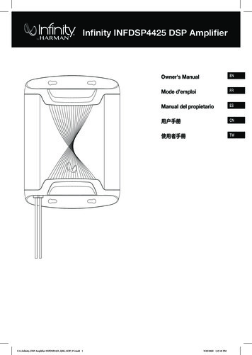
Infinity INFDSP4425 DSP AmplifierOwner's ManualENMode d’emploiFRManual del propietarioES用户手册CN使用者手冊CA Infinity DSP Amplifier INFDSP4425 QSG SOP V5.indd 1TW9/29/2020 1:47:45 PM
THANK YOU FOR YOUR PURCHASE . . .Your product has been designed to provide you the performance and ease of operation you expect from Infinity. Take timeto read this manual before operating or installing your amplifier. This manual describes general installation guidelines andoperation instructions. Please note that proper installation of mobile audio components requires qualified experience withmechanical and electrical procedures. If you do not have the knowledge and tools to perform this installation, we stronglyrecommend consulting an authorized Infinity dealer about your installation options.ENTABLE OF CONTENTSPRODUCT DESCRIPTION.2WHAT'S IN THE BOX.2INSTALLATION AND WIRING.2SETTING THE SOUND.4SPECIFICATIONS.6TROUBLESHOOTING.6CA Infinity DSP Amplifier INFDSP4425 QSG SOP V5.indd 19/29/2020 1:47:45 PM
Infinity INFDSP4425 DSP AmplifierPRODUCT DESCRIPTION Using the amplifier as a template, mark the locations of theholes on the mounting surface.The Infinity DSP Amplifier is an audio processor for fine-tuning ofaftermarket audio systems. It is a self-contained audio system with4-channel powered audio outputs and 2-channel preamp outputs,an easy-to-use tuning interface a novice can understand, anddetailed tuning capabilities to satisfy even experienced installers.With a USB connection to access the tuning interface using aWindows PC, you can control fully variable crossovers, selectable0-to-48 dB slopes, time delay, 31-band parametric or graphic EQadjustment, assignable input-to-output mixer with input channelsumming, channel gain, master volume control, clipping indicatorto ensure the audio output is not distorted, and ability to save upto 10 presets. Drill pilot holes in the mounting surface. Attach the amplifier to the mounting surface with the includedsheet metal screws and washers.WHAT'S IN THE BOX1x amplifier4x tie wraps1x power/speakercableStainless steelmounting hardware1x spare fuse1x USB to PC cable2x Infinity stickers1x owner’s manual1X4X4X 4XPower and Ground Connections1X4X1X1X1X2XINSTALLATION AND WIRINGIMPORTANT: Disconnect the vehicle’s negative (–) batteryterminal before beginning the installation. Wear protective eyewear when using tools. Choose a safe mounting location. Check clearances on bothsides of the location. Be sure that screws will not puncturebrake or fuel lines or wiring harnesses, and that wire routing willnot interfere with vehicle operation. Use caution when drillingor cutting. When making electrical connections, make sure they aresecure and properly insulated. Do not mount the amplifier with the heat sink facing downward,as this interferes with cooling.CA Infinity DSP Amplifier INFDSP4425 QSG SOP V5.indd 2 Power: Connect the yellow 12V power wire to the positiveterminal of the vehicle’s battery. Make sure the 15A fuse andfuse holder are within 18" (457mm) of the battery. Ground: Connect the black GND wire to the negative terminalof the vehicle’s battery, or to the vehicle’s chassis near thebattery with a screw. NOTE: If possible, remove any paint fromthe chassis for best contact. It is recommended to use a starwasher below the ring connector for a secure connection. Remote-In: Connect the red remote turn-on wire to the“Remote Out” lead of the source unit, if using low-level signalinputs with an aftermarket stereo. NOTE: If you are usinghigh-level signal inputs (your vehicle’s speaker wires), you canchoose to have the 12-volt DC offset feature turn the amplifieron when you turn on the vehicle power, or the audio-sensingfeature turn on the amplifier when it detects audio signal. Ineither case, you will not have to connect the remote turn-onwire and can tape or cap it off to prevent the introduction ofnoise. Remote-Out: Connect the blue remote-out wire to externaldevices that require 12V turn-on after the Infinity INFDSP4425.This connection will allow turn-on of 12V devices after theamplifier wakes from turn-on by 12V remote-in, DC offset oraudio signal sensing input. When all connections are made, plug the harness into theamplifier.Power/Protect indicatorsThe power light will illuminate in green when the amplifier is gettingpower and playing. The protect light will illuminate in red if the ampenters protect mode in the event of conditions such as over/undervoltage, amplifier output circuit failure, or excessive heat.9/29/2020 1:47:45 PMEN
Speaker Output ConnectionsConnect your speakers to the wires of the speaker output wiringharness, observing proper polarity: connect each positive ( ) leadto the appropriate positive ( ) speaker terminal, and negative (-)lead to the appropriate negative (-) speaker terminal. Then plug thespeaker output wiring harness into the DSP Amplifier.OUTPUT INPUT PWRCH 5-6 PRE-OUTREMOTETURN-ONMODEREM DC AUDIOINPUTLEVELLOWPCR R R RR R L L - -GBNAD TPRTHIPWRF F F FL L R R - -CH 1-4 LOW INF F R RR L L R- - - -F F R RR L L R OIU NTOUTPUT INPUT REMIMPORTANT: None of the speaker output channels can be bridged.ENTo speakersRemote turn-on (blue)to stereo REM outFuse holder, 15A fuseChassis ground (-)18" (46cm)Wire colorOutput channelWhiteFront left White/BlackFront left –GrayFront right Gray/BlackFront right –GreenRear left Green/BlackRear left –PurpleRear right Purple/BlackRear right –Connecting a second amplifier (sold separately)BatteryTo incorporate more power into your system, you can senda second amplifier a full-range audio signal using the preampoutputs of the INFDSP4425. Use an RCA patch cable to connectthe preamp outputs to the preamp inputs of the second amplifier.Signal input Line-level inputs: If your source unit offers front and rearpreamp outputs, connect them to the front and rear line-levelinputs on the wire harness using RCA patch cables.Note: when using low-level signals and remote turn-on lead, setthe “Turn-on Mode” switch to “REM” and the “Input Level” switch to“LOW”.To speakers amplifierTURN-ONMODE123REM DC AUDIO4INPUTLEVELLOWHI High-level inputs: If your audio system’s source unit doesnot have line-level outputs, connect the speaker output wiresof your source unit to the high-level input wires of the amplifierharness.Connecting the remote bass level control (soldseparately)The INFDSP4425 is compatible with the optional Infinity RBCremote bass level controller, available at your local Infinity dealer.To connect it, plug into the appropriate input on the control panelof the INFDSP4425. Mount the remote in a convenient location,such as under the dash, using sheet metal screws.TURN-ONMODEOUTPUT INPUT PWRCH 5-6 PRE-OUTVehicle speaker wiresINPUTLEVELCH 1-4 LOW INLOWWire colorHigh-level inputOrangeFront left Orange/BlackFront left -BlueFront right Blue/BlackFront right -RedRear left Red/BlackRear left -YellowRear right Yellow/BlackRear right -REMOTETURN-ONMODEREM DC AUDIOREM DC AUDIOINPUTLEVELLOWPCR R R RR R L L - -F F R RR L L R- - - -GBNAD TPRTHIPWRF F F FL L R R - -F F R RR L L R O IU NTOUTPUT INPUT REMHINOTE: When using high-level signals, set the “Turn-on Mode” switchto “DC” (to turn on when it receives battery power) or “AUDIO” (to turnon when it senses signal from your source unit), and the “Input Level”switch to “HI”.CA Infinity DSP Amplifier INFDSP4425 QSG SOP V5.indd 39/29/2020 1:47:46 PM
SETTING THE SOUNDDownload the tuning software from Infinity.com1. Connect to internet with your Windows PC or laptop and goto Infinity.comxxxx and download the Graphic User Interfacefor the INFDSP4425 Amplifier.2. Complete the software installation setup wizard before youconnect your computer to your Infinity DSP Amplifier.3. Double-click “Infinity DSP software” from its saved location.10. Installation Complete! Close setup wizard and continue tonext section. You should see this icon on your computerscreen.4. Double-click “USB driver” and click installNOTE: Make sure to allow it to make changes to your computer ifyour anti-virus software requests it.Connecting Infinity DSP Amplifier to your WindowsPC1. Connect your Windows PC to the INFDSP4425 with theincluded USB cable.OUTPUT INPUT PWRCH 5-6 PRE-OUTREMOTETURN-ONMODEREM DC AUDIOCH 1-4 LOW ININPUTLEVELLOWPCR R R RR R L L - -F F R RR L L R- - - -GBNAD TF F F FL L R R - -F F R RR L L R O IU NTPRTHIPWROUTPUT INPUT REM5. Double-click “setup.exe”.NOTE: Make sure to allow it to make changes to your computer ifyour anti-virus software requests it.6. Click “Next” in the Infinity DSP Software Setup Wizard.2. Make sure to turn your audio source down to a lowvolume level before powering your Infinity DSP Amplifier.3. Activate/power your audio system and make sure all partsare operating.NOTE: The INFDSP4425 will come with pre-flashed EQ profile thatwill act as “EQ Off” or preset 1.4.7. Select preferred installation folder, or click “next” to choosethe default location.8. Click “Next” to confirm installation. Again, make sure that youranti-virus protection allows installation to be completed.9. Sit back and wait while software installation completes CA Infinity DSP Amplifier INFDSP4425 QSG SOP V5.indd 4With your PC connected to the Infinity DSP Amplifier, doubleclick Infinity software icon on your PC and open DSP tuningsoftware.NOTE: If the software appears with a window showing “No CommPort Available”, close the software, disconnect the USB cable fromyour computer, and return to step 4. Otherwise, proceed to step 5.The DSP software will function when not connected to the amplifierif you would like to familiarize yourself with the software and createa pre-configured audio system setup.5. Connection complete! Continue on to Tuning Procedure 9/29/2020 1:47:48 PMEN
User Interface FunctionsENThe Infinity tuning software features the following controls:1. Connected and Disconnected. With this feature, youcan determine if the amplifier is communicating with yourWindows PC.2. Low and High. With this feature, you can determine if theamplifier is set to lo-level input or hi-level input on the amplifiercontrol panel.3. Assign speaker locations to channels. With this feature,you can designate the type of speaker and location in the careach output channel of the DSP is connected to.4. Individual channel volume control and muting. You canraise and lower the relative volume level of each channelindividually to ensure perfect level-matching and output.5. 0 /180 phase adjustment. You can set the phase of eachchannel individually for balanced, dynamic performance.6. Linking of paired channels. You can link paired channels toapply volume and tone controls evenly.7. Clipping indicator. Each channel features a clippingindicator to let you know if 10% or greater distortion ispresent. If it is, lower the volume level of the clipping channeluntil the indicator turns off. For best results, measure with a100Hz and 1kHz @ 0dB sine wave.8. Time delay. With time delay, you can adjust the focal point ofthe sound field to your desired location in the car. The closera speaker is to your desired focal-point location, the longerits delay should be. To adjust, drag the slider to the right toincrease the delay, and to the left to decrease it.9. Information display. This display shows you the followingstatistics:a. The master volume valueEXAMPLE: If you have connected a tweeter (high-frequencyresponse only) to input channel 1 and a midrange speaker(midrange-frequency response only) to channel 2, you cansum the signals of each of these inputs, and assign the new,full-range signal to a full-range speaker you have connectedto output channel 1.15. Save File. This allows you to save saving a preferred audiosystem configuration to a folder on your computer for uselater. It also allows you to retrieve a previous configurationfrom your computer and apply it to your connected amplifier.16. Settings. You can control the following options in the“Settings” menu:a. Language selection for the software: choose from English,Spanish, French, Chinese, and Japaneseb. Power settings for delaying the amplifier turn-on/off shouldyour vehicle require either optionc. Firmware upgrades and resetting the software to originalfactory settings17. Reset Output. This button lets you reset the type of speaker,and location in the vehicle, of each output channel.18. EQ Mode. This lets you choose either a 31 band parametricor graphic EQ to adjust for each channel.19. Parametric or Graphic EQ. You can apply custom EQcurves to each channel you have connected. To increase thelevel of a given frequency, drag the slider up. To lower it, dragthe slider down.20. EQ Setup. This EQ setup feature lets you click to select thechannels to which you want to apply EQ curves.NOTE: The FREQ, GAIN, and Q fields shows the valuesof the changes made by moving the EQ sliders. Only Gainis adjustable when in Graphic EQ Mode. Frequency, Gain,and Q are all adjustable in Parametric EQ Mode. Theseadjustments can be made using the sliders or enteringspecific values in the F, G, and Q fields.21. Bypass EQ and Restore EQ. “Bypass EQ” allow you toreturn your EQ settings to flat so you can hear the differencesmade during your tuning. “Restore EQ” returns all EQadjustments to the previous settings.22. Reset EQ – This button returns the EQ to factory settings.b. The current subwoofer volume level for channel 5 or 6, andadjustable from -30dB to 6dB when using the remotebass control.c. The voltage the amplifier is reading at the power inputd. The amplifier’s current operating temperaturee. Your current system configuration.10. X-OVER. You can adjust the crossover points of the highpass and low-pass crossovers for each channel to maximizethe performance efficiency of each speaker connected tothe DSP Amplifier. The selectable crossover slope for eachchannel can be set to 0/6/12/18/24/30/36/42/48dB.11. Speaker location view. This shows which amplifier channelsare in use, and the locations of the corresponding speakersin the vehicle.12. Master Volume. You can raise or lower the volume of theentire system, or mute the entire system. Drag the slider up toraise the volume, and down to lower it. Click the speaker iconto mute the audio system.13. Write/Delete. “Write” lets you save up to 10 preferred audiosettings as presets, which you can apply to the amplifier. Click“write”, then click a preset number to save a preset. Click“delete”, then click a preset number to delete a preset.14. Input Mixer. The Input Mixer feature lets you assign the audiosignal from an input channel to a specific output channel.You can also sum the signals of multiple input channels andapply the resulting signal to a specific output channel, usuallyto allow a speaker to play the widest range of frequenciespossible when using speaker-level input signals.CA Infinity DSP Amplifier INFDSP4425 QSG SOP V5.indd 59/29/2020 1:47:48 PM
SPECIFICATIONSTROUBLESHOOTING No audio and POWER INDICATOR is off. RMS Power Output (Watts x Channel) @ 4-ohm: 25W x 4RMS Power Output (Watts x Channel) @ 2-ohm: 35W x 4Amplifier Class: Class A/BBattery Voltage Range (Volts): 8V to 16VSelectable Turn-on Modes: 12V, Audio Signal Sense, DCOffset, 12V remote outputLED Indicator: red/greenFrequency Response: 10Hz to 22kHz @ -3dBSignal-to-Noise Ratio: 80dBSignal-to-Noise Ratio (CEA-2006): 68dBTHD N @ 4-ohm: 10%Input Sensitivity, selectable: High-level or low-levelInput Sensitivity - Low Level: 680mV to 6VInput Sensitivity - High Level: 1.6V to 15VChannel 5 & 6 pre-out voltage: 4VVariable Crossovers: All Channels: HPF, LPF, Band-pass w/selectable 0 to 48dB slopeGain, variable: All Channels with PCSubwoofer level, variable: Channels 5 & 6 in PC software orusing accessory remote control from -30dB to 6dBFuse Rating: 15AMinimum Recommended Power/Ground Wire Gauge: 8awgSpeaker Level Inputs: YesRemote Bass Control: Yes, Infinity RBC sold separatelyLength: 9-3/8" (237.5mm)Width: 5-11/16" (144mm)Height: 1-15/16" (49.5mm)Weight: Approx. 1000gProtection: DC, OVP, UVP, OCP, OTP No voltage at BATT and/or REM terminals, or bad or noground connection. Check voltages at amplifier terminals withVOM.No audio and PROTECT INDICATOR flashes DC voltage on amplifier output. Amplifier may need service; seeenclosed warranty card for service information.No audio and PROTECT and POWER INDICATORSflash. Voltage less than 9V on BATT connection. Check vehiclecharging system.No audio and PROTECT INDICATOR is on. Amplifier is overheated. Make sure amplifier cooling is notblocked at mounting location. Verify that speaker-systemimpedance is within specified limits. Or, there may be voltagegreater than 16V (or less than 8V) on BATT connection.Check vehicle charging system.Amplifier fuse keeps blowing. The wiring is connected incorrectly or there is a short circuit.Review installation precautions and procedures. Check wiringconnections.Distorted audio. Gain is not set properly. Check Individual Channel Volume and/or Mater Volume settings. Check speaker wires for shorts orgrounds. Amplifier or source unit may be defective.Distorted audio and PROTECT INDICATOR flashes. Short circuit in speaker or wire. Remove speaker leads one ata time to locate shorted speaker or wire, and repair.Music lacks dynamics or "punch." Speakers are not connected properly. Use 0 /180 phaseadjustment, and check speaker connections at amplifier andspeaker.CA Infinity DSP Amplifier INFDSP4425 QSG SOP V5.indd 69/29/2020 1:47:48 PMEN
MERCI POUR VOTRE ACHAT. . .Votre produit a été conçu pour vous offrir les performances et la facilité d'utilisation que attendez d’Infinity. Prenez letemps de lire ce manuel avant d'utiliser ou installer votre amplificateur. Ce manuel décrit les directives d'installationgénérales et les instructions d'utilisation. Veuillez noter qu'une installation convenable de composants audio mobilesrequiert une expérience qualifiée et des procédures mécaniques et électriques. Si vous ne disposez pas desconnaissances et des outils permettant d'exécuter cette installation, nous vous recommandons fortement de consulter undistributeur agréé Infinity pour connaître vos options d'installation.FRTABLE DES MATIÈRESDESCRIPTION DU PRODUIT.8CONTENU DE LA BOÎTE.8INSTALLATION ET CÂBLAGE.8RÉGLAGE DU SON.10CARACTÉRISTIQUES TECHNIQUES.12RÉSOLUTION DES PROBLÈMES.12CA Infinity DSP Amplifier INFDSP4425 QSG SOP V5.indd 79/29/2020 1:47:48 PM
Amplificateur à DSP InfinityINFDSP4425DESCRIPTION DU PRODUITL’amplificateur à DSP d’Infinity est un processeur audio permettantle réglage fin des systèmes audio de seconde monte. C’est unsystème audio intégré qui comporte 4 canaux d’entrées audio actifs,2 canaux de sorties de préamplificateur, une interface de réglagesimple compréhensible par un novice et des capacités de réglagedétaillées pour satisfaire même les installateurs expérimentés. Avecune connexion USB permettant l’accès à l’interface de réglagedepuis un PC Windows, vous pouvez commander des filtresde croisement entièrement variables, des pentes de 0 à 48 dBsélectionnables, un retard, ajuster une égalisation paramétrique ougraphique à 31 bandes, un mélangeur d’entrées-sorties assignableavec sommation des canaux d’entrée, le gain des canaux,commander le volume principal, visualiser un indicateur de crêtepour garantir que la sortie audio n’est pas déformée et disposer dela possibilité d’enregistrer jusqu’à 10 préréglages. Ne montez pas l'amplificateur avec son radiateur dessous, carceci nuit à son refroidissement. En utilisant l'amplificateur comme gabarit, marquezl'emplacement des trous sur la surface de montage. Percez des trous pilotes dans la surface de montage. Fixez l'amplificateur à sa surface de montage avec les vis à tôleet rondelles incluses.FRCONTENU DE LA BOÎTE1 amplificateur4 attaches1 câble d'alimentationet de haut-parleursMatériel de fixationen acier inoxydable1 fusible derechange1 câble USB pour PC2 autocollantsInfinity1 mode d'emploi1X4XConnexions d'alimentation et de masse4X 4X1X4X1X1X1X2XINSTALLATION ET CÂBLAGEIMPORTANT : débranchez la borne négative de la batterie(-) du véhicule avant de commencer l'installation. Portez des lunettes de protection pour utiliser des outils. Choisissez un emplacement de montage sûr. Vérifiez lesespaces des deux côtés de l’emplacement. Veillez à ce quedes vis ne percent pas de canalisations de freins, de carburantou des faisceaux de câblage, et que le cheminement descâbles ne nuira pas à la sécurité de fonctionnement duvéhicule. Percez ou coupez avec prudence. Lors de la réalisation des connexions électriques, veillez à cequ'elles soient sûres et correctement isolées.CA Infinity DSP Amplifier INFDSP4425 QSG SOP V5.indd 8 Alimentation : branchez le fil d'alimentation jaune 12 V à laborne positive de la batterie du véhicule. Vérifiez que le fusibleet le porte-fusible de 15 A sont à moins de 457 mm (18") dela batterie. Masse : branchez le fil noir GND à la borne négative dela batterie de véhicule, ou au châssis du véhicule, prèsde la batterie, avec une vis. REMARQUE : Si possible,retirez la peinture du châssis pour un meilleur contact. Il estrecommandé d’utiliser une rondelle en étoile sous la cosse àœil pour une connexion sûre. Entrée de télécommande : connectez le fil d'allumagetélécommandé rouge au fil « Remote Out » de l'appareilsource, si vous utilisez les entrées de signal de niveau bas avecun appareil stéréo de seconde monte. REMARQUE : Si vousutilisez des entrées de signal de niveau haut (les câbles deshaut-parleurs de votre véhicule), vous pouvez choisir d’allumerl’amplificateur via la fonction de déport du 12 volts CC lorsquevous allumez le véhicule, ou via sa fonction de détection audio.Dans les deux cas, vous n'avez pas besoin de brancher lefil d'allumage télécommandé et pouvez le terminer avec del'adhésif ou un bouchon afin d'éviter l'introduction de bruit. Sortie télécommande : connectez le câble de sortie detélécommande bleu aux appareils externes qui nécessitent unallumage 12 V après l’Infinity INFDSP4425. Cette connexionpermettra l’allumage des appareils 12 V après l’éveil del’amplificateur par une entrée de télécommande 12 V, undéport de CC ou une entrée de détection de signal audio. Lorsque toutes les connexions sont effectuées, branchez lefaisceau sur l’amplificateur.9/29/2020 1:47:48 PM
Témoin d'alimentation / protectionLe témoin d’alimentation s’allume vert lorsque l'amplificateur estalimenté et diffuse un signal. Le témoin de protection s’allumerouge si l'amplificateur entre en mode de protection lorsqu'ilrencontre des conditions telles qu'une sur/sous-tension, un courtcircuit, une défaillance du circuit de sortie de l'amplificateur ou unechaleur excessive.OUTPUT INPUT PWRCH 5-6 PRE-OUTREMOTETURN-ONMODEINPUTLEVELREM DC AUDIOLOWPCR R R RR R L L - -F F R RR L L R- - - -GBNAD TF F F FL L R R - -F F R RR L L R OIU NTPRTHICH 1-4 LOW INPWROUTPUT INPUT REMREMARQUE : Si vous utilisez des signaux de niveau haut, réglez lecommutateur « Turn-on Mode » sur « DC » (pour l’activer lorsqu’il reçoitl’alimentation de la batterie) ou sur « AUDIO » (pour l’activer lorsqu’ildétecte le signal de votre unité source), et le commutateur « InputLevel » sur « HI ».Connexions des sorties de haut-parleursConnectez vos haut-parleurs aux fils du faisceau de câblagedes sorties des haut-parleurs, en respectant la polaritécorrecte : connectez chaque fil positif ( ) à la borne positive ( )correspondante du haut-parleur et le fil négatif (-) à la bornenégative (-) correspondante. Branchez ensuite le faisceau decâblage des sorties des haut-parleurs dans l’amplificateur DSP.IMPORTANT : Aucun canal de sortie des haut-parleurs ne peutêtre ponté.FRVers les hautparleursTélécommande d’allumage(bleu) vers la sortie REM stéréoMasse du châssis (–)Porte-fusible,fusible de 15A46 cm (18")Couleur du Violet/noirCanaux de sortieAvant gauche Avant gauche Avant droit Avant droit Arrière gauche Arrière gauche Arrière droit Arrière droit -Branchement d'un second amplificateur (venduséparément)Pour apporter plus de puissance à votre système, vouspouvez envoyer un signal audio pleine gamme à un deuxièmeamplificateur en utilisant les sorties de préamplificateur duINFDSP4425. Utilisez un câble de liaison RCA pour connecterles sorties de préamplificateur aux entrées de préamplificateur dusecond amplificateur.BatterieEntrées des signaux Entrées niveau ligne : Si votre appareil source offre dessorties de préamplificateur avant et arrière, connectez-les auxentrées niveau ligne avant et arrière du faisceau de câblage aumoyen de câbles de liaison RCA.Remarque : si vous utilisez des signaux de niveau bas et un fild'allumage télécommandé, réglez le commutateur « Turn-on Mode »sur « REM » et le commutateur « Input Level » sur « LOW ».TURN-ONMODE123REM DC AUDIO4INPUTLEVELLOWHI Entrées de niveau haut : si l’appareil source de votresystème audio n'a pas de sorties de niveau ligne, connectezles fils de sortie des haut-parleurs de votre appareil source auxfils des entrées de niveau haut du faisceau de l’amplificateur.Vers l’amplificateur des haut-parleursConnexion de la télécommande du niveau desgraves (vendue séparément)Le INFDSP4425 est compatible avec la télécommande de niveaudes graves Infinity RBC en option, disponible chez votre détaillantInfinity. Pour la connecter, branchez-la dans l’entrée appropriéedu panneau de commande du INFDSP4425. Installez latélécommande dans un endroit pratique, comme sous le tableaude bord, à l’aide de vis à tôle.TURN-ONMODEOUTPUT INPUT PWRCH 5-6 PRE-OUTREM DC AUDIOFils des haut-parleursdu véhiculeCouleur du uneJaune/noirTURN-ONMODEREM DC AUDIOINPUTLEVELCH 1-4 LOW INLOWREMOTEINPUTLEVELLOWPCR R R RR R L L - -F F R RR L L R- - - -GBNAD TPRTHIPWRF F F FL L R R - -F F R RR L L R O IU NTOUTPUT INPUT REMHIEntrée de niveau hautAvant gauche Avant gauche Avant droit Avant droit Arrière gauche Arrière gauche Arrière droit Arrière droit -CA Infinity DSP Amplifier INFDSP4425 QSG SOP V5.indd 99/29/2020 1:47:49 PM
RÉGLAGE DU SON9. Détendez-vous et attendez la fin de l’installation du logiciel Téléchargez le logiciel de réglage depuisInfinity.com1.Connectez-vous à Internet avec votre PC ou ordinateurportable Windows, accédez à Infinity.comxxxx et téléchargezl’interface utilisateur graphique de l’amplificateur INFDSP4425.2. Exécutez l’assistant de configuration de l’installationdu logiciel avant de connecter votre ordinateur à votreamplificateur DSP d’Infinity.3. Cliquez deux fois sur « Infinity DSP software » dansl’emplacement où il est enregistré.10. L’installation est terminée ! Fermez l’assistant de configurationet passez à la section suivante. Vous devriez voir cette icônesur l’écran de votre ordinateur.FR4. Cliquez deux fois sur « USB driver » puis cliquez sur Install.REMARQUE : Assurez-vous de lui permettre d’apporter desmodifications à votre ordinateur si votre logiciel antivirus le demande.Connexion de l'amplificateur DSP d'Infinity à votrePC Windows1. Connectez votre PC Windows au INFDSP4425 avec le câbleUSB inclus.OUTPUT INPUT PWRCH 5-6 PRE-OUTREMOTETURN-ONMODEREM DC AUDIOCH 1-4 LOW ININPUTLEVELLOWPCR R R RR R L L - -F F R RR L L R- - - -GBNAD TF F F FL L R R - -F F R RR L L R O IU NTPRTHIPWROUTPUT INPUT REM5. Cliquez deux fois sur « setup.exe ».REMARQUE : Assurez-vous de lui permettre d’apporter desmodifications à votre ordinateur si votre logiciel antivirus le demande.2. Veillez à réduire le son de votre source audio à un faiblevolume avant d’allumer votre amplificateur DSP d’Infinity.3. Activez/allumez votre autoradio et vérifiez que tous sescomposants fonctionnent.6. Cliquez sur « Suivant » dans l’assistant de configuration dulogiciel DSP d’Infinity.REMARQUE : le INFDSP4425 est fourni avec un profild'égalisation déjà flashé qui aura le rôle « EG désactivé » oupréréglage 1.4. Votre PC étant connecté à l’amplificateur DSP d’Infinity,cliquez deux fois sur l’icône du logiciel Infinity sur votre PC etouvrez le logiciel de réglage du DSP.7. Sélectionnez le dossier d’installation de votre choix ou cliquezsur « Suivant » pour choisir l’emplacement par défaut.8. Cliquez sur « Suivant » pour confirmer l’installation. Encoreune fois, assurez-vous q
Download the tuning software from Infinity.com 1. Connect to internet with your Windows PC or laptop and go to Infinity.comxxxx and download the Graphic User Interface for the INFDSP4425 Amplifier. 2. Complete the software installation setup wizard before you . anti-virus protection allows installation to be completed. 9. Sit back and wait .




![Tuning Fork Crack [32 64bit]](/img/53/ansritbgmbzmsmdwl2vu-06-e1e5783f74e84991333bbca449aa905d-file.jpg)