Transcription
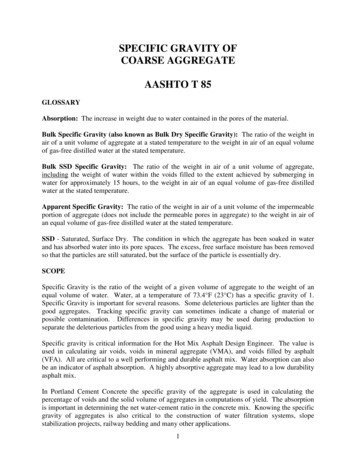
AASHTO Design andMaterial SpecificationChangesLRFD BDS Section 6, Various ArticlesKarl H. FrankConsultantNSBA
Bolts2
ASTM SpecificationsHigh Strength Bolts New Specification Combines 4 Specificationsinto 1 for both buildings and bridges-F3125–––––A325 Standard Hex BoltF1852 (A325 Tension Control)A490 Standard Hex BoltF2280 (A490 Tension Control) Metric The old names become Grades3
F3125 Significant Changes Grade A325- Fu 120 ksi for all diameters (results inan increase in shear capacity for bolts 1 in.) Annex A1- Table gives permitted coatings and overtapping required for nuts– No hot dip or mechanical galvanizing of Grade A490 bolts– F1136 and F2833 Zinc/Aluminum Allowed on all GradesA325 and A490 Rotational Capacity Test in Appendix A2– Reduced requirements for A490 bolts– Recommend Specifying Lubricated Nuts for Black A490Bolts4
AASHTO LRFD Changes Bolt Shear StrengthSlip Critical CategoriesStandard Hole SizesGirder Field Splice DesignKHF
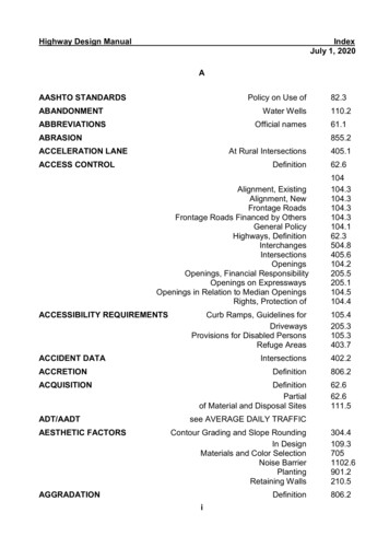
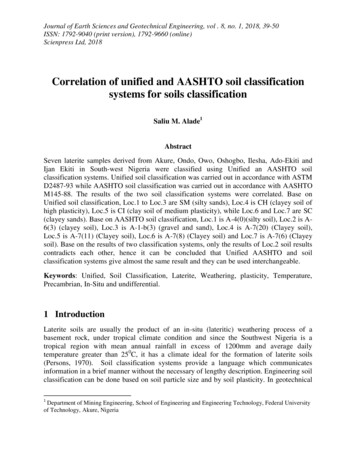
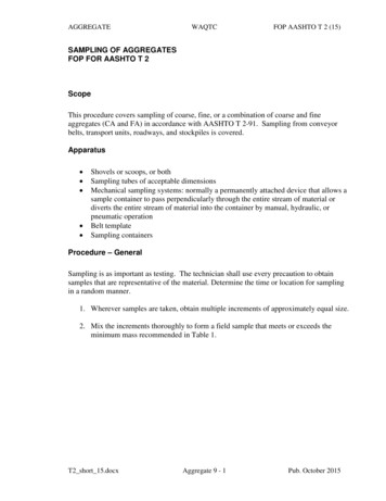
Shear Strength6.13.2.7 Initial Length Reduction– Changed from 0.8 to 0.9– Long Joint from 50 to 38 in. Bolts with threads in the shear plane: (web bolts)– 0.45( old value 0.38) Bolts with threads excluded from the shear plane:– 0.56(old value 0.48) The nominal shear resistance of a bolt in lap tensionconnections greater than 38 in. in length shall be takenas 0.83 times the values above (0.9x0.83 0.75).KHF
Unequal Bolt Shear In Long JointsBolt Shear
Joint Length Shear Strength ReductionsDesign Strength/ Single Bolt Capacitylength10.900.800.750.64Old Design Spec.One Bolt38 50 in.Connection Length
Bolt Shear StrengthConnection Length 38 in.Threads NotExcluded fromShear Plane“N” BoltThreadsExcluded fromShear Plane“X” BoltShear Strength:0.9 x 0.62 x F x A0.56 x F x AShear Strength:0.9 x 0.62 x F x . A0.45 x F x AFs 0.80
Slip Capacity R n K h K s N s PtKh Hole Factor 1 (normal size holes)Ks Surface Condition Slip Coefficient 0.5(blasted or Zinc Rich)Ns Number of Slip Planes per BoltPtBolt Installed TensionPt 0.70 x Tensile Strength 0.70 x A tensile x FuNote Installed Tension Increasedfor A325 Bolts 1 in.Fs 1.0(Art.6.13.2.2)
AASHTO High Strength Bolt Single Shear Design Capacityfbb 0.8fs 0.8Diameter(in.)Ab (in2)Fub (ksi)Fub Ab (kip)Pt (kip)TypeA325FA325NA325XFub (ksi)Fub Ab (kip)Pt (kip)TypeA490FA490NA490XKs 0.5Kh 523.929.70.6010.785A325 Bolt12012072.294.23951fsRn (kip)19.525.526.033.932.342.2A490 Bolt15015090.2117.84964fsRn 712140.053.766.851.066.382.560.58580.299.8KHF
Slip Critical ConnectionsSlip CoefficientClassTypical SurfaceOldSpecificationNewSpecificationAMill Scale0.330.30BZinc Rich Paintand Blasted0.500.50CGalvanized0.330.30*DOrganic ZincRich-0.45*Do not wire brush the surfaceRequired tension for A325 1 in. diameter increasedKHF
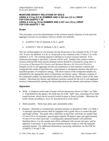
Post Slip Examination of ZincRich Paint Specimen
RCSC Fig. C-3.1Areas for Unqualified Paints1.2.3.Area Outside of Shaded Area mayhave Unqualified Paints.Edges of Plates Not Participating inDeveloping Slip Resistance.Therefore Do Not Have to Be inContact.
Footnote on Bolting New Hole Size– 1 inch and greater: Standard hole diameter offastener 1/8 in. Miss drilled holes- fill with fully tensionedhigh strength bolt (Category B fatiguestrength) New electric wrenches can be programmed forrequired turn of the nut
New Connection Design Criteria and Methods Remove applicability of the 75 percent andaverage rules in Article 6.13.1 to the design ofbolted and welded splices for flexural members. 75 percent rules are applicable to connections andsplices for primary members subject to axialtension or compression only. Clarify application of rules to primary memberssubjected to force effects acting in multipledirections due to combined loading.
Bolted Field Splices of FlexuralMembers Revised general article on design of bolted splices forflexural members implementing new simplifiedbolted splice design procedure Removal of check for slip of bolts during erection ofsteel The purpose is implementation ofsimplified design procedure and moreeconomical field splice designs.
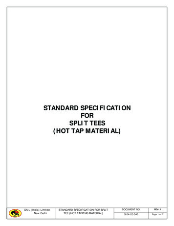
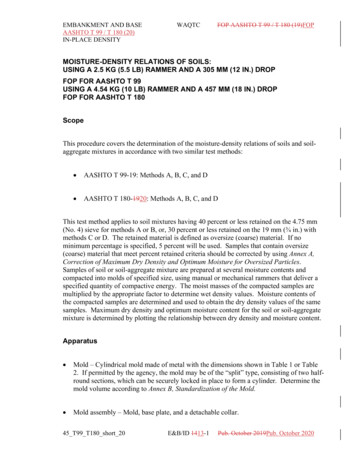
Expensive and Slow to Erect Field SpliceField Splice92 bolts in each web32 bolts each flangeTotal 312 bolts936 holesBolts: 312x 20 6,240Labor: 312x10 min 52 field hours each splice
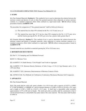
The Problem: Tub Girder SpliceField Splice36 each top flange80 bolts in each web85 bolts bottom flange634 bolts1,902 holesBolts: 634x 20 12,680Labor: 634x10 min 106 field hours each splice
Splice Design Procedure1. Design Flange Connection to Develop the SmallerDesign Yield Resistance of the Connected FlangesDesign Yield Resistance:Pfy Fyf A e fuFu An A gA e fFyyf 2. Design Web Connection to Develop the SmallerFactored Shear Resistance of the Connected WebsVr fv Vn20Two Rows of bolts minimum on each side of splice.
Positive Flange Moment Capacity CheckBottom Flange in TensionA D t ftt t haunch s22Pfy Fyf A eMoment Capacity:Pfy for the Bottom Flange x Moment Arm to Mid- Depthof Deck21 (Fyf x Ae ) x A
Negative Flange Moment and Non CompositeCapacity CheckIgnore Tensile Contribution of Deck ReinforcementPfy ( top ) Fyf A eA D t ft t fc 22Pfy (bot .) Fyf A eMoment Capacity:Smallest Value of Pfy x Distance Between Flange Centroids22 (Fyf x Ae ) x A
If Moment From Flanges is Not Sufficientto Resist Factored Design MomentCalculate Additional Resisting Moment to be Provided by theWebApplied Web Moment Factored Moment –Moment Resistance of the Flange Factored Design Moment- (Pfy x A)Resisting Web moment Hw x Aw ( horizontal web bolt force x moment arm)Yields Horizontal Web Force Hw :Hw Factored Design Moment Pfy x AAw Web MomentAW23
Calculation of Horizontal Web ForceComposite Section in Positive BendingtsAw D t haunch22Resultant Web Horizontal Force:HwH
Calculation of Horizontal Web ForceComposite Section in Negative Bending orNon-Composite SectionHw2D2D2D2Hw2Hw D Web Moment 2 2 Resultant Web Horizontal Force:HwWeb Moment D/4
Web Splice Force Vector Resultant from Moment and ShearR Vr 2 Hw 2 fv Vn 2 Hw 2Hw Horizontal Force in Web To Resist Design MomentVr Vertical Force in Web Factored Shear Resistance of the Web26
Design ComparisonNumber of Bolts RequiredGirderDepth in.DesignMethodTop 811180 202859
Validation Finite Element Analysis9916THK.16THK.55T H K.T H K.716THK.8T H K.10982 4 S p a . @ 4 in c hTHK.55204 Web Bolts916THK.T H K.81027161093 3 S p a . @ 3 in c h1028100 Web Bolts“Simplified Design of Bolted Splice Connections for Steel Girders” – Frank, Ocel, andGrubb916THK.28
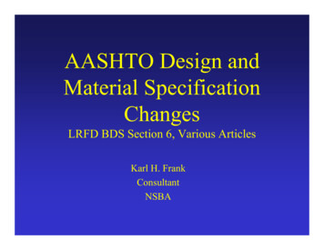
FEA Model Descriptiono Shell element models in Abaquso Adapted fastener models from NCHRP 12-84o Five loading scenarios–––––Pure positive momentPure negative moment *High shear (as little moment as possible) *Proportion design positive moment/shearProportional design negative moment/shear ** deck not present29
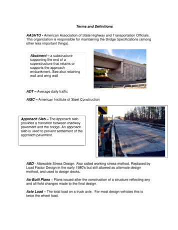
Results – High Shear3,000Left Support Reaction (kip)Step 262,5002,0001,500Step 26Vu1,000Current Method50000.00Proposed Method0.501.001.502.00Left Support Displacement (inches)2.5030
Results – High ShearVon Mises Stresses @ Step 26CURRENTPROPOSED“Simplified Design of Bolted Splice Connections for Steel Girders” – Frank, Ocel, and Grubb31
Results – High ShearBolt Shear Forces @ Step 26CURRENTPROPOSED“Simplified Design of Bolted Splice Connections for Steel Girders” – Frank, Ocel, and Grubb17
Results – Prop Neg Mom & ShearLeft Support Reaction (kip)3,0002,5002,0001,500Vu1,000500Current MethodProposed Method00.000.501.001.502.002.503.003.504.00Left Support Displacement (inches)20
Results – Prop Neg Mom & ShearVon Mises Stresses @ VuCURRENTPROPOSED21
Results – Prop Neg Mom & ShearBolt Shear Forces @ VuCURRENTPROPOSED24
Anticipated Effect on Bridges:– Application of the new proposed design provisions forbolted field splices will typically result in a few morebolts in the flange splices and significantly fewer boltsin the web splices than under the current designprovisions.– The overall simplification in the design procedureshould result in easier interpretation of the provisions,faster and more efficient design of field splices, andmore consistent and cost-effective designs.– Clarifications to the application of the 75 percent andaverage rules to the design of connections and splices inprimary members at the strength limit state subject tocombined force effects should also be beneficial todesigners.
Bolted Field Splices Documentwww.steelbridges.org/nsbasplice37
Design Tools – Splice Spreadsheet
NSBA Splice Spreadsheet NSBA Splice Spreadsheet– Plate Girder Bolted Splice Design Tool.– 8th Edition AASHTO Design SpecificationCompliant.– Updated May 2019.– Subscribe to NSBA Newsletter for ice
NSBA Splice Spreadsheet Download
NSBA Splice Spreadsheet Download
NSBA Splice Spreadsheet DownloadDesign GuideSpreadsheet Download
Result of Changes to Field SpliceDesign Reduced Design Effort andCost, Lower Connection Costs,& Faster ErectionKHF
A New Day- Another Bridge44
AASHTO Design and Material Specification Changes LRFD BDS Section 6, Various Articles Karl H. Frank Consultant NSBA. Bolts 2. ASTM Specifications High Strength Bolts New Specification Combines 4 Specifications into 1 for both buildings and bridges-F3125 –A325 Standard Hex Bolt –F1852 (A325 Tension Control) –A490 Standard Hex Bolt –F2280 (A490 Tension Control) – Metric The .