Transcription
INSTALLATION GUIDE AND TERMINAL BLOCKSPECIFICATIONSNI PXIe-4339 and TB-4339/B/C8 Ch, 24-bit, 25.6 kS/s Universal Bridge Input ModuleThis document explains how to install, configure, and set up the NI PXIe-4339 SC Expressuniversal bridge module and TB-4339/4339B/4339C (TB-4339/B/C) terminal block. Driversupport for the NI PXIe-4339 was first available in NI-DAQmx 14.2. For the list of devicessupported by a specific release, refer to the NI-DAQmx Readme, available on theversion-specific download page or installation media.Note The keying of these terminal blocks prevents them from connecting to othermodules that could be damaged by the voltage present on the terminal block.However, you should only use these terminal blocks with their supported modules.ContentsElectromagnetic Compatibility Guidelines . 2What You Need to Get Started . 2Installation . 3Install the Software . 3Unpack and Install the Module. 3Connect the Signals . 5Install the Terminal Block . 8Confirm SC Express Module Recognition . 9Run Test Panels . 10Take an NI-DAQmx Measurement . 11NI-DAQmx Channels and Tasks. 11Configure a Task Using the DAQ Assistant in MAX . 11Use Your SC Express Module in an Application . 12Programming Examples . 12Terminal Block Removal. 12Module Removal . 13Create a Simulated Device . 14More Information . 15Troubleshooting. 15Specifications (TB-4339/B/C) . 15Calibration Interval. 15
Electrical . 15Mechanical. 16Physical . 16Environmental Specifications . 16Operating Environment. 16Storage Environment . 17Shock and Vibration . 17Safety .17Safety Standards . 17Electromagnetic Compatibility . 18CE Compliance . 18Online Product Certification . 18Environmental Management. 19World Wide Support and Services. 19Electromagnetic Compatibility GuidelinesThis product was tested and complies with the regulatory requirements and limits forelectromagnetic compatibility (EMC) stated in the product specifications. These requirementsand limits provide reasonable protection against harmful interference when the product isoperated in the intended operational electromagnetic environment.This product is intended for use in industrial locations. However, harmful interference mayoccur in some installations, when the product is connected to a peripheral device or test object,or if the product is used in residential or commercial areas. To minimize interference with radioand television reception and prevent unacceptable performance degradation, install and use thisproduct in strict accordance with the instructions in the product documentation.Furthermore, any modifications to the product not expressly approved by National Instrumentscould void your authority to operate it under your local regulatory rules.To ensure the specified EMC performance, operate this product only withshielded cables and accessories. Cables connected to the PXIe-4339 using theTB-4339/B/C terminal block must use only twisted, shielded pair cables. Use onetwisted, shielded pair for each EX /EX-, RS /RS-, AI /AI-, AO /AOGND,PFI0/DGND, and T /DGND that is cabled. Cable shields must be terminated tochassis ground at both ends.CautionWhat You Need to Get StartedTo set up and use a NI PXIe-4339 module with a TB-4339/B/C terminal block, you need thefollowing items: 2Hardware –NI PXIe-4339 module–TB-4339/B/C terminal blockni.com NI PXIe-4339/TB-4339 Installation Guide and Terminal Block Specifications
–NI PXI Express chassis–Cabling and sensors as required for your applicationTools–Number 1 and 2 Phillips-head screwdrivers–1/8 in. flathead screwdriver–Long-nose pliers–Wire cutter–Wire insulation stripperDocumentation–Read Me First: Safety and Electromagnetic Compatibility–NI PXIe-4339 and TB-4339/B/C Installation Guide and Terminal Block Specifications–NI PXIe-4339 User Manual–NI PXI Express chassis user manualYou can download needed documents from ni.com/manuals.InstallationInstall the SoftwareNote You must be an administrator to install NI software and devices on yourcomputer.Ensure that the following software is installed before installing the SC Express hardware:1.Your application software, such as LabVIEW, LabWindows /CVI or .NET.2.NI-DAQmx—NI PXIe-4339 modules were first supported in NI-DAQmx 14.2.Note For detailed NI software version support, refer to the NI-DAQmx Readme.Back up any applications before upgrading software or modifying the application.Unpack and Install the ModuleRemove the packaging and inspect the module. Contact NI if the module is damaged. Do notinstall a damaged module.Caution The module is static sensitive. Always properly ground yourself and theequipment when handling or connecting to the module.NI PXIe-4339/TB-4339 Installation Guide and Terminal Block Specifications National Instruments 3
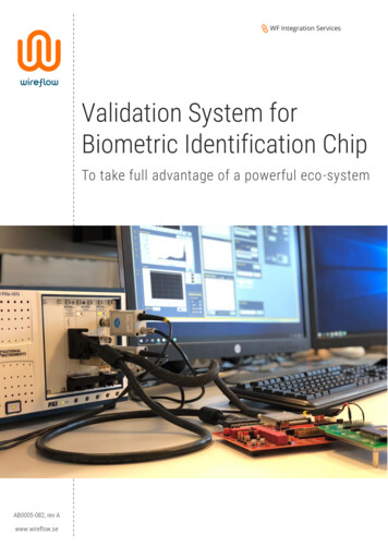
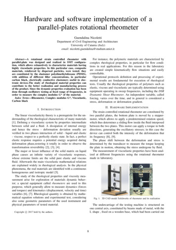
Complete the following steps to install the SC Express module while referring to Figures 1and 2:Note To maintain forced air cooling in the PXIe system, refer to the MaintainForced-Air Cooling Note to Users.1.Plug in your chassis before installing the NI PXIe-4339. The power cord grounds thechassis and protects it from electrical damage while you install the module.2.Make sure the chassis is powered off.To protect yourself, the chassis, and the NI PXIe-4339 from electricalhazards, leave the chassis powered off until you finish installing the NI PXIe-4339module.Caution3.Touch a metal part on the chassis to discharge any accumulated static electricity.4.Identify a supported PXI Express slot in the chassis. SC Express devices can be placed onlyin PXI Express Peripheral slots, PXI Express Hybrid Peripheral slots, and PXI ExpressSystem Timing slots. Refer to the chassis documentation for details.Figure 1. Symbols for PXI Express/ PXI Express Hybrid/ PXI SlotsNI PXIe-1062Q112PXI Express System Controller SlotPXI Peripheral Slot23434PXI Express Hybrid Peripheral SlotPXI Express System Timing Slot5.Remove the filler panel, and touch any metal part of the chassis to discharge staticelectricity.6.Place the module edges into the module guides at the top and bottom of the slot.When installing the module, make sure both edges are positioned insidethe guides and that the module components do not come into contact with adjacentmodules.Caution7.4Slide the module along the guides until it reaches the rear connector then seat the moduleby pushing the front panel until it is flush with the front panel of the chassis. ni.com NI PXIe-4339/TB-4339 Installation Guide and Terminal Block Specifications
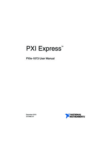
8.Secure the module to the chassis using the front-panel captive screws, shown in Figure 2.Tighten the screws to 0.31 N · m (2.7 lb · in.).Figure 2. Installing SC Express ModulesCOOLINGCLEARANCE AND FAN FILTER MAINTENANCEREQUIRED. SENIE MANUAL.PXIe-1062Q11Captive ScrewsConnect the SignalsCaution For EMC compliance, operate this product with shielded cables andaccessories.To connect signals to the terminal block, refer to Figures 3 and 4 while completing the followingsteps:Note You can find the pinout names and locations in Measurement & AutomationExplorer (MAX) at any time by right-clicking the device name under Devices andInterfaces and selecting Device Pinouts.1.Loosen the captive top cover screws and remove the top cover.2.Loosen the strain-relief screws and remove the strain-relief bar.3.Prepare the shielded signal wire by stripping the insulation no more than 7 mm (0.28 in.).4.Run the shielded signal wires through the strain-relief opening.NI PXIe-4339/TB-4339 Installation Guide and Terminal Block Specifications National Instruments 5
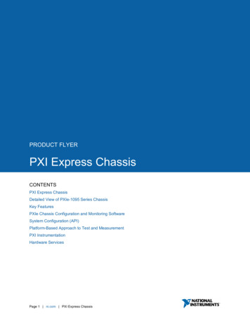
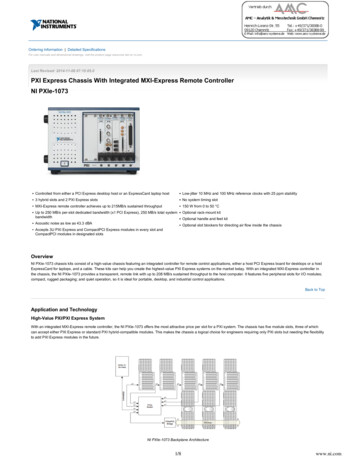
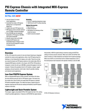
Figure 3. TB-4339/B/C Parts Locator Diagram161726435489123Strain-Relief ScrewsStrain-Relief BarTie Wrap Holes5.6456Ground LugsTerminal Block to Module ConnectorCaptive Top Cover Screws789Top CoverTie WrapsShielded Signal WiresInsert the stripped end of the shielded signal wires fully into the appropriate terminal. Referto the label next to each screw terminal to determine the function of the terminal. TheNI PXIe-4339 User Manual provides more detailed wiring information. Make sure noexposed wire extends past the screw terminal. Exposed wire increases the risk of a shortcircuit that can cause circuit failure. ni.com NI PXIe-4339/TB-4339 Installation Guide and Terminal Block Specifications
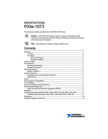
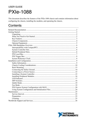
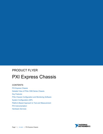
C6Figure 4. TB-4339/B/C Circuit Board Parts Locator DiagramR3U4R8C4R9B1C1R1oCR1CR2R5 R6 R4A1J10RS C5C3U1C1U3U2T SCAAI-AI-AI AI T-QTRQTRT-SCAEX EX SCARS RS RSR20SCASCAJ14T R23R16R26T-SCAEXAIAI QTRCH6J11EX RS AO EX-R15CH7R12R22SCAJ15AO J19J17QTRSCAJ16T-EX CH4R11QTREX-SCAAIAI RS-SCAEX-T J3J7J4R14AO SCARS-R18RS T RS-SCAJ18RS SCAAO TR13EX T R21QTRCH5TSCAT CH0QTREX J9AI T-AI J13AI RSEX-J8AI-J12AI-AO AI-J1SCAR25J2N114RS EX-T CH1QTREX EX-SCACH2AI AO RS-R19R10AI-AO RS-TR24EX-T DGNDPFI0J5RS-CH3J6AO R2oCOPYRIGHT 2013AOGNDAIGND155411A-01LNI TB-4339R7C2oS/NEX RS FOR PATENTS: NI.COM/PATENTSNote Refer to the NI PXIe-4339 User Manual for wiring diagrams showing variousways to connect sensors to the TB-4339/B/C.6.Tighten the terminal screws to a torque of 0.2 to 0.25 N · m (1.77 to 2.21 lb · in.).Caution Any wires connected to the ground must be sufficiently insulated fromhigh voltage.7.Use the ground lugs to attach a shield wire to the ground.NoteRefer to the NI PXIe-4339 User Manual for details about shielding thesignals.8.Reinstall the strain-relief bar and tighten the strain-relief screws.9.Use tie wraps to connect the shielded signal wires to the tie-wrap holes for additional strainrelief when necessary.10. Reinstall the top cover and tighten the captive top cover screws.NoteFor information about sensors, go to ni.com/sensors.NI PXIe-4339/TB-4339 Installation Guide and Terminal Block Specifications National Instruments 7
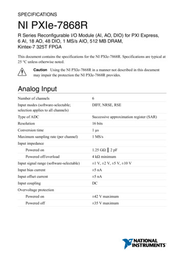
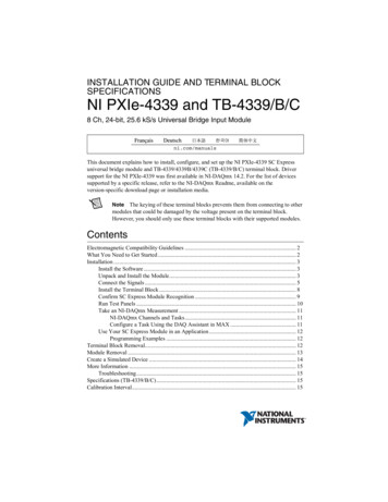
Install the Terminal BlockRefer to Figure 5 to install the terminal block on the module while completing the followingsteps:1.Move the TB-4339/B/C into position in front of the NI PXIe-4339 and engage thealignment feature with the guide on the associated module.Figure 5. Installing the TB-4339/B/C on the NI PXIe-4339 IRUQEREESL.AUNAMNIPXIe-1062Q356412NI PXIe ControllerNI PXIe Chassis34Mounting ScrewTB-4339/B/C Terminal Block56NI PXIe-4339 ModuleAlignment Feature2.Attach the TB-4339/B/C to the NI PXIe-4339 module by pushing the terminal blockstraight into the module. A spring mechanism will lock in the bottom of the terminal block.3.Tighten the mounting screw at the top of the TB-4339/B/C to attach it to the NI PXIe-4339module.For safety purposes and to prevent damage to equipment when high voltagesare present, all SC Express modules and terminal blocks are keyed to preventconnection between incompatible terminal blocks, modules, and/or cables.Note4.8Power on the chassis. ni.com NI PXIe-4339/TB-4339 Installation Guide and Terminal Block Specifications
Figure 6 shows an example SC Express system setup.Figure 6. Sample SC Express SystemCOOLINGNIPXIe-1CLEARANCE AND FAN FILTER MAINTENANCEREQUIRED. SEE MANUAL.062Q121Terminal Block2Signal InputConfirm SC Express Module RecognitionTo confirm module recognition, complete the following steps:Note Software support for the NI PXIe-4339 is provided by NI-DAQmx. The DAQGetting Started Guide, which you can download at ni.com/manuals, offersstep-by-step NI-DAQmx instructions for installing software and hardware,configuring channels and tasks, and getting started developing an application. Fordetailed NI software version support, refer to the NI-DAQmx Readme.1.Launch MAX.2.Expand Devices and Interfaces, and expand the chassis in which the module is located toconfirm that MAX detects the module and terminal block. The terminal block shouldappear beneath its associated module. If your module or terminal block is not listed, press F5 to refresh MAX. If the module is still not recognized, go to ni.com/support/daqmx.NI PXIe-4339/TB-4339 Installation Guide and Terminal Block Specifications National Instruments 9
Using an NI-DAQmx simulated device, you can test NI-DAQmx applicationswithout installing hardware. Refer to the Create a Simulated Device section forinstructions for creating NI-DAQmx simulated devices.TipRight-click the module name and select Self-Test. When the self-test completes, averification message appears. If an error occurs, refer to ni.com/support/daqmx.3.For information about sensors, go to ni.com/sensors.Run Test Panels1.In MAX, expand Devices and Interfaces select the chassis in which the module is located.2.Right-click the device, and select Test Panels.10 ni.com NI PXIe-4339/TB-4339 Installation Guide and Terminal Block Specifications
3.Click Start to test device functions, or Help for operating instructions.To troubleshoot errors, refer to the NI-DAQmx Help, or go to ni.com/support.Take an NI-DAQmx MeasurementNI-DAQmx Channels and TasksRefer to the NI-DAQmx Help for complete information about channels and tasks.Use the DAQ Assistant to configure virtual channels and tasks in MAX or in your application.Configure a Task Using the DAQ Assistant in MAXComplete the following steps to create a task using the DAQ Assistant in MAX:1.In MAX, right-click Data Neighborhood and select Create New to open the DAQAssistant.2.Select NI-DAQmx Task and click Next.3.Select Acquire Signals.4.Select the analog input, and the measurement type, such as strain.5.Select the physical channel(s) to use and click Next.6.Name the task and click Finish.7.Configure the individual channel settings. Each physical channel you assign to a taskreceives a virtual channel name. To modify the input range or other settings, select thechannel. Click Details for physical channel information. Configure the timing andtriggering for your task. Click Run.NI PXIe-4339/TB-4339 Installation Guide and Terminal Block Specifications National Instruments 11
Use Your SC Express Module in an ApplicationFor NI software version compatibility, refer to the NI-DAQmx Readme, available from Start»All Programs»National Instruments»NI-DAQmx.To get started with data acquisition in your application software, refer to the tutorials listed inTable 1.Table 1. DAQ Assistant Tutorial LocationsApplicationTutorial LocationLabVIEWGo to Help»Search the LabVIEW Help. Next, go to Getting Started withLabVIEW»Getting Started with DAQ»Taking an NI-DAQmx Measurementin LabVIEW.LabWindows/CVIGo to Help»Contents. Next, go to Using LabWindows/CVI»Data Acquisition»Taking an NI-DAQmx Measurement in LabWindows/CVI.MeasurementStudioGo to NI Measurement Studio Help»Getting Started with the MeasurementStudio Class Libraries»Measurement Studio Walkthroughs»Walkthrough:Creating a Measurement Studio NI-DAQmx Application.LabVIEWSignalExpress*Go to Help»Taking an NI-DAQmx Measurement in SignalExpress.*LabVIEW SignalExpress, an easy-to-use configuration-based tool for data logging applications, is atStart»All Programs»National Instruments»LabVIEW SignalExpress.Programming ExamplesNI-DAQmx includes example programs to help you get started developing an application.LabVIEW and CVI examples are located at Help»Find Examples in your application software.Text-based code examples are located at All Programs»National Instruments»NI-DAQ»Text-Based Code Support»ANSI C Examples. Modify example code and save it in anapplication, or use examples to develop a new application or add example code to an existingapplication.For other examples, go to ni.com/info and enter the Info Code daqmxexp. For additionalexamples, refer to zone.ni.com .Terminal Block RemovalTo remove the terminal block, refer to Figure 7 while completing the following steps:Note1.12The chassis can be powered on or off when removing the terminal block.Loosen the terminal block mounting screw located at the top of the terminal block. ni.com NI PXIe-4339/TB-4339 Installation Guide and Terminal Block Specifications
2.To remove the terminal block:a.Raise the latch release using a flathead screwdriver to disengage the latch.b.With the latch release raised, grasp the terminal block and pull it away from themodule.Figure 7. Removing the TB-4339/B/C from the NI PXIe-4339 .EIRUQEREESL.AUNAMNIPXIe-1062Q5123.Mounting ScrewLatch Release34NI PXIe ControllerNI PXIe Chassis5TB-4339/B/C Terminal BlockStore the terminal block in an antistatic protective bag.Module RemovalCautionDo not remove a module with the power on. Doing so can damage themodule.To remove the module, refer to Figure 8 while completing the following steps:Note To maintain forced air cooling in the PXIe system, refer to the MaintainForced-Air Cooling Note to Users.1.Make sure that the chassis is powered off before removing the module.2.Loosen the captive screws on the top and bottom of the module.NI PXIe-4339/TB-4339 Installation Guide and Terminal Block Specifications National Instruments 13
Do not pull the front panel to remove the module. Doing so may causemodule components to come into contact with adjacent modules, causing damage tothe modules.Caution3.Pull the captive screws to unseat the module and slowly slide the module along the guides.4.Replace the filler panel in the empty slot.5.Store the module in an antistatic protective bag.Figure 8. Removing SC Express ModulesCOOLINGCLEARANCE AND FAN FILTER MAINTENANCEREQUIRED. SEE MANUALNIP11XIe.-1062Q2Captive Screws (Use to remove modules.)2Front Panel (Do not use to remove modules.)Create a Simulated DeviceTo run examples without the hardware installed, use an NI-DAQmx simulated device. To createa simulated device in MAX:1.Launch MAX.2.Right click Devices and Interfaces»Create New.3.From the dialog, select Simulated NI-DAQmx Device or Modular Instrument.4.Type 4339 in the text box at the top of the window.5.Select the device from the list provided.6.Click OK.14 ni.com NI PXIe-4339/TB-4339 Installation Guide and Terminal Block Specifications
More InformationAfter you install NI-DAQmx, the NI-DAQmx documentation is available from Start»AllPrograms»National Instruments»NI-DAQ. Additional resources are online at ni.com/gettingstarted.You can access online device documentation by right-clicking your module in MAX andselecting Help»Online Device Documentation. A browser window opens to ni.com/manuals with the results of a search for relevant documents. If you do not have Web access,documents for supported modules are included on the NI-DAQmx disc.Troubleshooting Go to ni.com/support/install or ni.com/kb. If you need to return your National Instruments hardware for repair or device calibration,go to ni.com/info and enter rdsenn to start the Return Merchandise Authorization(RMA) process.Specifications (TB-4339/B/C)Note NI PXIe-4339 module specifications are located in the NI PXIe-4339Specifications document.All performance specifications are typical unless otherwise noted. These specifications are validwithin the full operating temperature range.Calibration IntervalTB-4339/B/C . No calibrationElectricalResistorsTB-4339Quarter bridge completion. 120 Ω 0.1%, 10 ppm/ CShunt calibration resistor . 50 kΩ 0.1%, 10 ppm/ CTB-4339BQuarter bridge completion. 350 Ω 0.1%, 10 ppm/ CShunt calibration resistor . 100 kΩ 0.1%, 10 ppm/ CTB-4339CQuarter bridge completion. 1 kΩ 0.1%, 10 ppm/ CShunt calibration resistor . 100 kΩ 0.1%, 10 ppm/ CTrace resistance (screw terminal to connector)EX , EX- . 20 mΩNI PXIe-4339/TB-4339 Installation Guide and Terminal Block Specifications National Instruments 15
MechanicalScrew terminal wire gauge .1.5 mm2 (14 AWG), maxPhysicalFigure 9. TB-4339/B/C Dimensions15.28 cm(6.02 in.)12.95 cm(5.10 in.)WeightTB-4339/B/C .700 g (24.7 oz)Clean the hardware with a soft, nonmetallic brush. Make sure that thehardware is completely dry and free from contaminants before returning it to service.CautionEnvironmental SpecificationsMaximum altitude.2,000 m (800 mbar), at 25 C ambienttemperaturePollution Degree .2Indoor use onlyOperating EnvironmentAmbient temperature range .0 C to 55 C(Tested in accordance with IEC 60068-2-1 andIEC 60068-2-2. Meets MIL-PRF-28800FClass 3 low temperature limit andMIL-PRF-28800F Class 2 high temperaturelimit.)Relative humidity range.10% to 90%, noncondensing(Tested in accordance with IEC 60068-2-56.)16 ni.com NI PXIe-4339/TB-4339 Installation Guide and Terminal Block Specifications
Storage EnvironmentAmbient temperature range . -40 C to 71 C(Tested in accordance with IEC 60068-2-1 andIEC 60068-2-2. Meets MIL-PRF-28800FClass 3 limits.)Relative humidity range. 5% to 95%, noncondensing(Tested in accordance with IEC 60068-2-56.)Shock and VibrationOperating shock . 30 g peak, half-sine, 11 ms pulse(Tested in accordance with IEC 60068-2-27.Meets MIL-PRF-28800F Class 2 limits.)Random vibrationOperating . 5 Hz to 500 Hz, 0.3 grmsNon-operating. 5 Hz to 500 Hz, 2.4 grms(Tested in accordance with IEC 60068-2-64.Non-operating test profile exceeds therequirements of MIL-PRF-28800F, Class 3.)SafetyMeasurement Category. I1Caution Do not connect the TB-4339/B/C to signals or use for measurementswithin Measurement Categories II, III or IV.Caution The protection provided by the TB-4339/B/C can be impaired if it is usedin a manner not described in this document.Safety StandardsThis product meets the requirements of the following standards of safety for electrical equipmentfor measurement, control, and laboratory use: IEC 61010-1, EN 61010-1 UL 61010-1, CSA 61010-1Note For UL and other safety certifications, refer to the product label or the OnlineProduct Certification section.1Measurement Categories CAT I and CAT O are equivalent. These test and measurement circuits are notintended for direct connection to the MAINS building installations of Measurement Categories CAT II,CAT III, or CAT IV.NI PXIe-4339/TB-4339 Installation Guide and Terminal Block Specifications National Instruments 17
Electromagnetic CompatibilityThis product meets the requirements of the following EMC standards for electrical equipmentfor measurement, control, and laboratory use: EN 61326-1 (IEC 61326-1): Class A emissions; Basic immunity EN 55011 (CISPR 11): Group 1, Class A emissions EN 55022 (CISPR 22): Class A emissions EN 55024 (CISPR 24): Immunity AS/NZS CISPR 11: Group 1, Class A emissions AS/NZS CISPR 22: Class A emissions FCC 47 CFR Part 15B: Class A emissions ICES-001: Class A emissionsNote In the United States (per FCC 47 CFR), Class A equipment is intended for usein commercial, light-industrial, and heavy-industrial locations. In Europe, Canada,Australia and New Zealand (per CISPR 11) Class A equipment is intended for useonly in heavy-industrial locations.Group 1 equipment (per CISPR 11) is any industrial, scientific, or medicalequipment that does not intentionally generate radio frequency energy for thetreatment of material or inspection/analysis purposes.NoteNote For the standards applied to assess the EMC of this product, refer to theOnline Product Certification section.CE ComplianceThis product meets the essential requirements of applicable European Directives as follows: 2006/95/EC; Low-Voltage Directive (safety) 2014/30/EU; Electromagnetic Compatibility Directive (EMC)Online Product CertificationRefer to the product Declaration of Conformity (DoC) for additional regulatory complianceinformation. To obtain product certifications and the DoC for this product, visit ni.com/certification, search by model number or product line, and click the appropriate link in theCertification column.18 ni.com NI PXIe-4339/TB-4339 Installation Guide and Terminal Block Specifications
Environmental ManagementNI is committed to designing and manufacturing products in an environmentally responsiblemanner. NI recognizes that eliminating certain hazardous substances from our products isbeneficial to the environment and to NI customers.For additional environmental information, refer to the Minimize our Environmental Impact Webpage at ni.com/environment. This page contains the environmental regulations anddirectives with which NI complies, as well as other environmental information not included inthis document.Waste Electrical and Electronic Equipment (WEEE)EU Customers At the end of the product life cycle, all products must be sent to aWEEE recycling center. For more information about WEEE recycling centers,National Instruments WEEE initiatives, and compliance with WEEE Directive2002/96/EC on Waste and Electronic Equipment, visit ni.com/environment/weee. ᄤֵᙃѻક ᶧ ࠊㅵ⧚ Ё RoHS Ё ᅶ᠋ National Instruments ヺড়Ё ᄤֵᙃѻકЁ䰤ࠊՓ ᶤѯ᳝ᆇ 䋼ᣛҸ(RoHS)DŽ݇Ѣ National Instruments Ё RoHS ড়㾘ᗻֵᙃˈ䇋ⱏᔩ ni.com/environment/rohs chinaDŽ (For information about China RoHS compliance,go to ni.com/environment/rohs china.)World Wide Support and ServicesThe National Instruments website is your complete resource for technical support. At ni.com/support you have access to everything from troubleshooting and application developmentself-help resources to email and phone assistance from NI Application Engineers.Visit ni.com/services for NI Factory Installation Services, repairs, extended warranty, andother services.Visit ni.com/register to register your National Instruments product. Product registrationfacilitates technical support and ensures that you receive important information updates from NI.National Instruments corporate headquarters is located at 11500 North Mopac Expressway,Austin, Texas, 78759-3504. National Instruments also has offices located around the world. Fortelephone support in the United States, create your service request at ni.com/support or dial1 866 ASK MYNI (275 6964). For telephone support outside the United States, visit theWorldwide Offices section of ni.com/niglobal to access the branch office websites, whichprovide up-to-date contact information, support phone numbers, email addresses, and currentevents.NI PXIe-4339/TB-4339 Installation Guide and Terminal Block Specifications National Instruments 19
Refer to the NI Trademarks and Logo Guidelines at ni.co
May 10, 2021