Transcription
sonic’s 3DMetal PrintingDesign Guideand FrequentlyAsked Questions
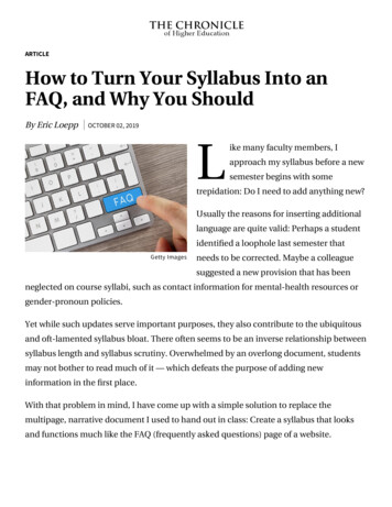
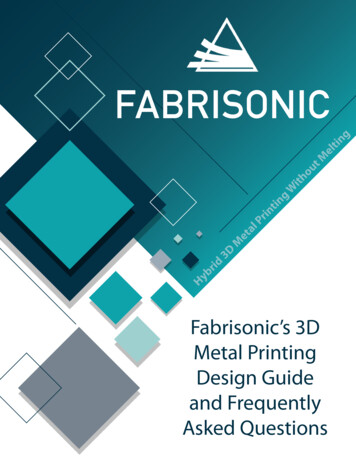
Ultrasonic Additive Manufacturing (UAM) is a revolutionary 3D printingtechnology that uses sound to merge layers of metal drawn from foil stock.The process produces true metallurgical bonds with full density and workswith a variety of materials. The patented technology: Allows welding materials without changing their metallurgical propertiesAllows for very complex internal geometriesCan embed electronics without damage or overheatingCan join multiple metals into one part (Al, Cu, Bronze, etc.)The UAM process involves building up solid metal objects throughultrasonically welding a succession of metal tapes into a three-dimensionalshape, with periodic machining operations to create the detailed shape ofthe resultant objects. The figure, at the bottom of the page, shows a rollingultrasonic welding system, consisting of two ultrasonic transducers and the(welding) horn. High-frequency (typically 20,000 hertz) ultrasonic vibrationsare locally applied to metal foil materials, held together under pressure, tocreate a weld. The vibrations of the transducer are transmitted to the diskshaped welding horn, which in turn creates an ultrasonic solid-state weldbetween the thin metal tape and a base plate. The continuous rolling of thehorn over the plate welds the entire tape to the plate. Successive layers arewelded together to build up height. This process is then repeated until a solidcomponent has been created.The fundamental distinguishing characteristic of UAM, in comparison toother metallic additive manufacturing technologies, is that it is a solid-statewelding process – meaning that melting of metals does not occur – with all ofthe attendant impact of high temperatures on material properties.Horn(Textured to engagethe metal foil)Transducer(Creates the shakingback and forth)To see an different infographic of “How It Works”, click the highlighted link.
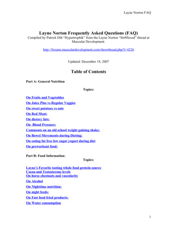
Our 3D metal printing process creates complex components that haveunique features and attributes not possible with traditional manufacturingtechniques. There are three main characteristics of the UAM process thatcustomers frequently gravitate to:Dissimilar 3D Metal JoiningThe solid-state nature of the ultrasonic bonding process used in UAMpermits joining of dissimilar metals without the formation of brittle intermetallics as seen in fusion processes. A wide range of material combinationshave been successfully bonded using ultrasonics such as; Al/Cu, Al/Fe, Al/ Ti,Ta/Fe, Ag/Au and Ni/ Stainless. Fabrisonicfrequently works with customers to ‘print’new metal combinations to meet specificengineering applications. By combining theproperties of multiple materials into a singlecomposite, they can be created with specificengineering properties such as coefficientof thermal expansion (CTE), modulus, andyield strength.Fabrication of Complex Internal GeometryDue to our unique machining capabilities, the welding process can bestopped at any point and internal three-dimensional channels can bemachined. Subsequently, the additive process continues to build up metal,sealing in complex 3D flow paths. This capability can be exploited tomake RF waveguides, chemical mixing plates, as well as heat exchangers.Fabrisonic routinely builds heatexchangers that utilize complexinternal structure as well asdissimilar metals such as aluminumand copper. Aluminum heatexchangers have been made withburst pressures of over 3000 PSI.Embed Sensors in Solid MaterialSensors and electrical controls are used widely in all industries. However,a common problem is degradation of exposed components over time dueto corrosion, impact, and wear.Ideally, in such situations, it wouldbe best to bury the electronics insolid metal. With Fabrisonic’s lowtemperature welding, sensors canbe embedded in solid metal partswith no damage to the sensor.Embedded fiber optic in aluminum
Frequently Asked Questions - MaterialsDo you provide the feed material or can it be purchased from any rawmetal provider? What are the requirements for it (geometrical form,dimensions and tolerances, weight, material)?Foil can be found readily on the open market, and we can suggest vendorsthat work well for us. One issue that pops up during development is that manysuppliers have a minimum order quantity of about 440 lbs. While this is finefor production applications, it can add costs to development or low volumemanufacturing. If the material is one Fabrisonic stocks, we try to work withthe customer to supply small quantities. With material that is costly, such astantalum, we are able to get much smaller quantities in sheet form.In general, we look for foils with a mill finish rolled to a thickness between .05.38mm (.002”-.015”). Foil tapes and sheet should be coiled on metal (preferred)or cardboard (usable) rings or cylinders. Our tape feeder can support a coil ofminimum ID of 200mm (8”) and max ID of 500 mm (20”) with a max weight of 20Kg. However, we can also accept customer materials as long as they can meetrequirements which includes both tape and sheet.I have read that the machine usually operates with 1” wide metal tape.Can it feed on tapes with different width? On sheets? If so, what are thelimitations?There are physics-based limitations to the width of the contact area of thewelding surface which is approximately 1” wide. However, a wide variety offeedstocks can be used. Fabrisonic welding system is setup for a 1” wide tape.However, the guide rollers in the tape feeder can be easily swapped to allow forsmaller width tapes.Fabrisonic’s tape feed systems are not designed to feed sheet stock. However,sheet product can be presented to the machine manually, and the weld headcan be rastered over the surface to weld an entire sheet. Care must be taken toprevent wrinkles in the sheet such as vacuuming the sheet in place. In the past,production machines have had an added pneumatic arm for picking up sheetfrom a hopper to the side of the machine and placing it in the proper location.In general, the process is very forgiving of thickness variation but is sensitiveto width variation. We have found that industry standard foil slitting machineshold a sufficient tolerance, but we have not quantified the tolerance on ourown.What materials work in the UAM process?Fabrisonic has extensive experience with aerospace aluminums. Aluminums inthe following series have all been welded successfully: 1xxx, 2xxx, 3xxx, 5xxx,6xxx, 7xxx.A myriad of dissimilar metal combinations have been successfully carried outincluding, Al/Cu, Al/Ti, Al/Fe, Al/Mo, Ni/Fe, Ni/Ti, Al/Ta, Al/Invar, Al/MMC’s. Thefollowing chart was developed for Ultrasonic Metal Welding (a precursor ofUAM). While we have not tried all of these combinations, theoretically, theyshould be feasible.The ultrasonic welding process is not suitable to join metals to non-metals.
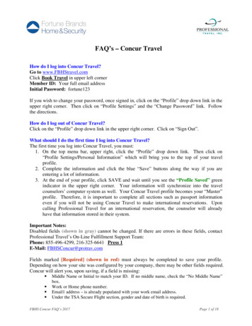
However, non-metallics canbe embedded into solidmetal parts. Embeddingreinforcing memberssuch as boron and siliconcarbide fibers or stainlesssteel meshes into metalmatrices is simple withUltrasonic AdditiveManufacturing. Since theprocess can be interruptedand modified at any point,structural componentscan be augmented intoany metal matrix to formsuperior, high performancecomposite structures. Theseadvanced materials can bestiff and lightweight, theperfect combination for high stress, weight-critical environments.What temperature does the metal reach during the ultrasonic weldingprocess? We understand that it’s a cold process, but what is the maximumtemperature we should expect?This is highly material dependent. In aluminums, we typically see a maximumtemp of 140 C (284 F). Copper generally welds at a lower temperature.However, in titanium we find that the material needs to go above the BetaTransus ( 880 C) to get good weld properties. We have also found that certainmaterials weld better when the baseplate is pre-heated. Typical pre-heattemperatures are 66-121 C (150-250 F).How does the process affect embedded electronics? Are there limitationson sensitive equipment?Obviously, care has to be taken to avoid creating an electrical short circuit.We typically wrap electronics with Kapton tape (or similar) to isolate themelectronically. The three main concerns with the process are the high downforce (2000 N), the vibration (40 microns), at what temperature can theelectronic/sensor/fiber handle. To avoid the high forces, we typically machine apocket in a structure and drop the electronics in and weld over top. Dependingon the depth of the pocket, the part may or may not see a load. With lowamplitude ( 20 micron), it is possible to embed glass without breakage.Fabrisonic typically runs small experiments with new electronic components todetermine the max amplitude that can be used without damage to a particularembedded device.How does the welded material behave after the process? Can coating beapplied to the manufactured parts same as to standard parts?For the most part, the welded material behaves the same as material machinedout of normal plate product. The UAM process essentially cold rolls the materialas it is welding which can affect the material properties. Coatings can still beapplied per the normal processes. We have had success with anodizing, paints,and conversion coatings.
Frequently Asked Questions - GeometryWhat is the surface finish? How close can you hold tolerances?Fabrisonic’s production machines start out life as a commercial 3-Axis CNCmill. To the base mill, Fabrisonic adds it patented welding head for additivemanufacturing. The print head is treated as another tool in the CNC tool change(see video below). The additive head is used to add material to produce a partthat is near net shape. The mill can then be used to CNC machine final trueshape. The hybrid system allows for a mirror-like final surface finish as well astolerances of /-.0005”. Tolerances are further improved in that the part hasalways been in one machine. There is no error generally associated with partsthat have to be located in two or three machines during .be/saSrmgEZJzMThe machine lays tapes side by side with a small overlap, how sensitive theprocess to tolerances? How does the machine ensure it?This is an area where we are continually doing process improvement. If toomuch overlap is created, ridges form which can cause issues on subsequentlayers. If not enough overlap is created, we get small linear defects betweenadjacent horizontal tapes. Our most current tape feeder design can holdstandard tolerances on most geometries.Are the layers waterproof? Gas proof?We have made components that are waterproof and have passed helium leaktests down to 10-9 std cc/sec. However, we find that we must use a few layersof sheet directly above a channel (instead of tape) to ensure integrity dueto varying edge-to-edge tape gaps on the micro scale. Additionally, specialparameters with lighter force must be used for the first few layers above achannel to prevent tearing depending on the size of the gap.What are the geometrical limitations of the process?The first limitation is best described as a height-to-width ratio. Tall, skinny,structures, such as wall, looks like a simple beam. At a height-to-width ratio ofabout 0.7 the theoretical beam has a resonant frequency of 20 kHz. As we areinputting energy at 20 kHz, the structure is put into resonance, and fatigues ifwe get to a height to width ratio of 0.7-1.0. To avoid this limitation, we typicallybuild tall structures wider than needed and machine afterward to get true netshape.The second limitation is unsupported geometry. Our process uses severalthousand newtons of force in order to create a bond. For structures such asoverhangs, no normal force exists to push back and enable bonding. We havefound, however, that it is possible to make shallow overhangs such as by usingand undercut end mill. Additionally, we can build over enclosed cavities. Ingeneral, cavities of less than 15mm (.6”) are workable as the horn can weldon either side of the cavity. However, directly above the cavity there will be aregion of poor bonding, even with additional layers. A rule of thumb is that thebuild will ‘heal’ after a height equal to the width of the channel. Also, welds overpockets or cavities will have slight deformation, or bow, on the “ceiling” due to
the force applied during welding.A good thing to keep in mind, the 1” wide horn should be engaged over 75%of the horn width with sold material. Otherwise, the horn will tip to the sideand will create a flatness issues and leads to a poor bond. Larger voids canbe encapsulated using workarounds. For instance, in larger structures onecould machine a lip around a large void and placed a .75” plate on the lip.Subsequently, the weld can continue over the entire structure. The .75” platewould provide support for the build to continue.Have you tried support material?Support materials have always been important in the world of metal 3Dprinting to enable printing complex overhangs and intricate internal features.When it comes to Ultrasonic Additive Manufacturing (UAM), which is obviouslythe coolest of all the metal additive forms, many fillers have been tried. Somepast examples are ice, rock candy, and even other metals. The key to a goodsupport material for UAM is for it to be easy to add and remove from featureswithout affecting the metal’s properties but still providing rock-solid supportfor welding.Fabrisonic has been working with NASA on building out-of-this-world heatexchangers where support materials are sometimes necessary. Through theseprograms, we’ve come up with two support materials that could revolutionizethe future of UAM printing heat exchangers, cold plates and even radiofrequency devices. One invention is a highly stiffened water-soluble mix thatcan be easily added to features while printing and then simply flushed out ofthe part after printing is complete. Newly developed supports are helping pushthe boundary of what’s possible when printing with UAM.What about overhung geometry?If possible, we prefer to machine overhangs after welding using the CNCcapability in our machines. By waiting until after welding we can avoidresonance and buckling modes. However, if the required part has an internaloverhung geometry, we must address it during the build. We have found thatthere is a large market that supplies custom end mills that can cut below andaround a given geometry.Below you can find a chart of common undercut bits that we use:Image courtesty of Harvey Tool
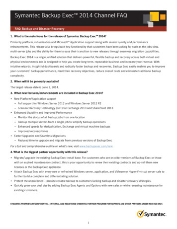
Frequently Asked Questions - ProcessHow does an ultrasonic weld work? Is it a real weld?Ultrasonic welding of metals has been around since the 1960s. The processuses ultrasonic vibrations to create a friction-like relative motion between twosurfaces that are held together under pressure. This action, in turn, causesshearing and plastic deformation between asperities of the opposing surfaces,which disperses surface oxides and contaminants. As the asperities collapse,metal-to-metal contact is increased creating solid-state bonding between theparts through heat and pressure. The welds are truly metallurgically bondedwithout the need for heat or melting.Ultrasonic vibration creates highshear stress and slip that disruptsurface films and oxides.Friction creates heat less than halfof its melting temperature causingasperities to collapse pushingnascent metal onto nascent metal.A solid-state metallurgical bondis created.What are the parameters which control the welding process?Key process variables for a given material include: welding speed, weldingamplitude, welding force, and in some cases, preheat.What is the build rate?Many 3D printers measure material deposition in fractions of a cubic inch perhour. At these rates, parts are restricted to a small envelope that can be printedin a reasonable amount of time. Fabrisonic’s line of SonicLayer machines printfrom 15 to 30 cubic inches per hour. This allows for much larger build volumes.
The SonicLayer 4000 has a bed of 24 in x 36 in while the SonicLayer 7200 canaccommodate parts 6 ft x 6 ft x 3 ft.How do you program the machine? Do I need a special file format?The SonicLayer series is controlled 100% through the use of industrystandard G-code programming. The operator imports native CAD geometryinto software that generates the tool paths for both welding and machining.The G-code is automatically generated and is then moved to the machine forexecution.What are the consumables for this machine?There will be some maintenance of the horn. When it wears down, the weldingsurface will need to be retextured. When welding aluminum, a horn texture isgood for several months of production. However, for harder materials like steeland titanium the horn could need retextured a few times a month.The only other major consumables are standard milling consumables such asend mills, tool inserts, vacuum materials, oil/grease, and milling coolant.Is the process of replacing milling tools an automated process or manual?The SonicLayer 4000 and 7200 are commercial grade 3-Axis and sometimes5-Axis CNC mills that we have integrated our welding system. Thus, it hasan automatic 20 position tool changer built in, and all tools are called usingtraditional G-code commands.Are there any special safety instructions for the ultrasonic process that weshould be aware of? Safety distance from working machine? Special safetyequipment?The largest safety concern is noise level. We have measured sound of 85 dBdirectly next to the machine. Hearing protection is recommended for thosearound the machine for long durations. In addition, typical safety standardsare also recommended for operating this kind of machinery such as eye wearprotection.
Hybrid3DMetalPrintingWithoutMeltingFABRISONICFor more information on whatFabrisonic has to offer, visitwww.fabrisonic.com, email atinfo@fabrisonic.com, or call at614.688.5197.
ultrasonic welding system, consisting of two ultrasonic transducers and the (welding) horn. High-frequency (typically 20,000 hertz) ultrasonic vibrations are locally applied to metal foil materials, held together under pressure, to create a weld. The vibrations of the transducer are transmitted to the disk-shaped welding horn, which in turn .