Transcription
Z77 Extreme4-MUser ManualVersion 1.2Published June 2013Copyright 2013 ASRock INC. All rights reserved.1
Copyright Notice:No part of this manual may be reproduced, transcribed, transmitted, or translated inany language, in any form or by any means, except duplication of documentation bythe purchaser for backup purpose, without written consent of ASRock Inc.Products and corporate names appearing in this manual may or may not be registered trademarks or copyrights of their respective companies, and are used only foridentification or explanation and to the owners’ benefit, without intent to infringe.Disclaimer:Specifications and information contained in this manual are furnished for informational use only and subject to change without notice, and should not be constructedas a commitment by ASRock. ASRock assumes no responsibility for any errors oromissions that may appear in this manual.With respect to the contents of this manual, ASRock does not provide warranty ofany kind, either expressed or implied, including but not limited to the implied warranties or conditions of merchantability or fitness for a particular purpose.In no event shall ASRock, its directors, officers, employees, or agents be liable forany indirect, special, incidental, or consequential damages (including damages forloss of profits, loss of business, loss of data, interruption of business and the like),even if ASRock has been advised of the possibility of such damages arising fromany defect or error in the manual or product.This device complies with Part 15 of the FCC Rules. Operation is subject to the following two conditions:(1) this device may not cause harmful interference, and(2) this device must accept any interference received, including interference thatmay cause undesired operation.CALIFORNIA, USA ONLYThe Lithium battery adopted on this motherboard contains Perchlorate, a toxicsubstance controlled in Perchlorate Best Management Practices (BMP) regulationspassed by the California Legislature. When you discard the Lithium battery in California, USA, please follow the related regulations in advance.“Perchlorate Material-special handling may apply, e terms HDMI and HDMI High-Definition Multimedia Interface, and the HDMIlogo are trademarks or registered trademarks of HDMI Licensing LLC in the UnitedStates and other countries.2
Contents1 Introduction. 51.11.21.31.4Package Contents.Specifications.Motherboard Layout.I/O Panel .5613142 Installation. 162.12.22.32.42.52.62.72.8Screw Holes. 16Pre-installation Precautions . 16CPU Installation. 17Installation of Heatsink and CPU fan. 19Installation of Memory Modules (DIMM). 20Expansion Slots (PCI Express Slots). 22SLITM and Quad SLITM Operation Guide. 24CrossFireXTM, 3-Way CrossFireXTM and QuadCrossFireXTM Operation Guide. 282.9 Dual Monitor and Surround Display Features. 332.10 ASRock Smart Remote Installation Guide. 362.11 Jumpers Setup . 372.12 Onboard Headers and Connectors . 382.13 Serial ATA (SATA) / Serial ATA2 (SATA2) Hard DisksInstallation . 442.14 Serial ATA3 (SATA3) Hard Disks Installation . 442.15 Hot Plug and Hot Swap Functions for SATA / SATA2HDDs . 452.16 Hot Plug and Hot Swap Functions for SATA3 HDDs . 452.17 SATA / SATA2 / SATA3 HDD Hot Plug Feature andOperation Guide . 462.18 Driver Installation Guide . 482.19 Installing Windows 7 / 7 64-bit / VistaTM / VistaTM64-bit With RAID Functions . 482.20 Installing Windows 7 / 7 64-bit / VistaTM / VistaTM 64-bit/ XP / XP 64-bit Without RAID Functions . 492.20.1 Installing Windows XP / XP 64-bit Without RAIDFunctions. 492.20.2 Installing Windows 7 / 7 64-bit / VistaTM /VistaTM 64-bit Without RAID Functions. 503
3 UEFI SETUP UTILITY. 513.1 Introduction. 513.23.33.43.53.63.73.83.1.1 UEFI Menu Bar.3.1.2 Navigation Keys.Main Screen.OC Tweaker Screen.Advanced Screen.3.4.1 CPU Configuration.3.4.2 North Bridge Configuration.3.4.3 South Bridge Configuration.3.4.4 Intel(R) Rapid Start Technology.3.4.5 Intel(R) Smart Connect Technology.3.4.6 Storage Configuration.3.4.7 Super IO Configuration.3.4.8 ACPI Configuration.3.4.9 USB Configuration.Hardware Health Event Monitoring Screen.Boot Screen.Security Screen.Exit Screen.5152525358596162636465666768697071724 Software Support. 734.1 Install Operating System.4.2 Support CD Information.4.2.1 Running Support CD.4.2.2 Drivers Menu.4.2.3 Utilities Menu.4.2.4 Contact Information.4737373737373
Chapter 1: IntroductionThank you for purchasing ASRock Z77 Extreme4-M motherboard, a reliable motherboard produced under ASRock’s consistently stringent quality control. It deliversexcellent performance with robust design conforming to ASRock’s commitment toquality and endurance.In this manual, chapter 1 and 2 contains introduction of the motherboard and stepby-step guide to the hardware installation. Chapter 3 and 4 contains the configuration guide to BIOS setup and information of the Support CD.Because the motherboard specifications and the BIOS software might beupdated, the content of this manual will be subject to change without notice. In case any modifications of this manual occur, the updated versionwill be available on ASRock website without further notice. You may findthe latest VGA cards and CPU support lists on ASRock website as well.ASRock website http://www.asrock.comIf you require technical support related to this motherboard, please visitour website for specific information about the model you are using.www.asrock.com/support/index.asp1.1 Package ContentsASRock Z77 Extreme4-M Motherboard(Micro ATX Form Factor: 9.6-in x 9.6-in, 24.4 cm x 24.4 cm)ASRock Z77 Extreme4-M Quick Installation GuideASRock Z77 Extreme4-M Support CD2 x Serial ATA (SATA) Data Cables (Optional)1 x I/O Panel Shield1 x ASRock SLI Bridge CardASRock Reminds You.To get better performance in Windows 7 / 7 64-bit / VistaTM / VistaTM 64bit, it is recommended to set the BIOS option in Storage Configuration toAHCI mode. For the BIOS setup, please refer to the “User Manual” in oursupport CD for details.5
1.2 SpecificationsPlatformCPUChipsetMemoryExpansion SlotGraphics- Micro ATX Form Factor: 9.6-in x 9.6-in, 24.4 cm x 24.4 cm- Premium Gold Capacitor design (100% Japan-madehigh-quality Conductive Polymer Capacitors)- Supports 3rd and 2nd Generation Intel CoreTM i7 / i5 / i3 inLGA1155 Package- Digi Power Design- 4 2 Power Phase Design- Supports Intel Turbo Boost 2.0 Technology- Supports Intel K-Series unlocked CPU- Supports Hyper-Threading Technology (see CAUTION 1)- Supports Intel Rapid Start Technology and Smart ConnectTechnology with Intel Ivy Bridge CPU- Intel Z77- Dual Channel DDR3 Memory Technology (see CAUTION 2)- 4 x DDR3 DIMM slots- Supports DDR3 2800 (OC)/2400(OC)/2133(OC)/1866(OC)/1600/1333/1066 non-ECC, un-buffered memory- Max. capacity of system memory: 32GB (see CAUTION 3)- Supports Intel Extreme Memory Profile (XMP)1.3/1.2- 2 x PCI Express 3.0 x16 slots (PCIE1/PCIE3: single at x16(PCIE1) / x8 (PCIE3) or dual at x8/x8 mode)(see CAUTION 4)* PCIE 3.0 is only supported with Intel Ivy Bridge CPU. WithIntel Sandy Bridge CPU, it only supports PCIE 2.0.- 1 x PCI Express 2.0 x16 slot (PCIE4: x4 mode)- 1 x PCI Express 2.0 x 1 slot- Supports AMD Quad CrossFireXTM, 3-Way CrossFireXTMand CrossFireXTM- Supports NVIDIA Quad SLITM and SLITM* Intel HD Graphics Built-in Visuals and the VGA outputs canbe supported only with processors which are GPUintegrated.- Supports Intel HD Graphics Built-in Visuals: Intel QuickSync Video, Intel InTruTM 3D, Intel Clear Video HDTechnology, Intel InsiderTM, Intel HD Graphics 2500/4000,Intel Advanced Vector Extensions (AVX)- Pixel Shader 5.0, DirectX 11 with Intel Ivy Bridge CPU.Pixel Shader 4.1, DirectX 10.1 with Intel Sandy Bridge CPU- Max. shared memory 1760MB (see CAUTION 5)6
- Three VGA Output options: D-Sub, DVI-D and HDMI(see CAUTION 6)AudioLANRear Panel I/OSATA3- Supports HDMI 1.4a Technology with max. resolution up to1920x1200 @ 60Hz- Supports DVI with max. resolution up to 1920x1200 @ 60Hz- Supports D-Sub with max. resolution up to 2048x1536 @75Hz- Supports Auto Lip Sync, Deep Color (12bpc), xvYCC andHBR (High Bit Rate Audio) with HDMI (Compliant HDMImonitor is required) (see CAUTION 7)- Supports HDCP function with DVI and HDMI ports- Supports Full HD 1080p Blu-ray (BD) / HD-DVD playbackwith DVI and HDMI ports- 7.1 CH HD Audio with Content Protection(Realtek ALC898 Audio Codec)- Premium Blu-ray audio support- PCIE x1 Gigabit LAN 10/100/1000 Mb/s- Realtek RTL8111E- Supports Wake-On-LAN- Supports LAN Cable Detection- Supports Energy Efficient Ethernet 802.3az- Supports PXEI/O Panel- 1 x PS/2 Keyboard Port- 1 x D-Sub Port- 1 x DVI-D Port- 1 x HDMI Port- 1 x Optical SPDIF Out Port- 4 x Ready-to-Use USB 2.0 Ports- 1 x eSATA3 Connector- 2 x Ready-to-Use USB 3.0 Ports- 1 x RJ-45 LAN Port with LED (ACT/LINK LED and SPEEDLED)- HD Audio Jack: Rear Speaker/Central/Bass/Line in/FrontSpeaker/Microphone (see CAUTION 8)- 2 x SATA3 6.0 Gb/s connectors by Intel Z77, support RAID(RAID 0, RAID 1, RAID 5, RAID 10, Intel Rapid Storage andIntel Smart Response Technology), NCQ, AHCI and HotPlug functions- 2 x SATA3 6.0 Gb/s connectors by ASMedia ASM1061,7
support NCQ, AHCI and Hot Plug functions(SATA3 A1 connector is shared with eSATA3 port)USB3.0ConnectorBIOS FeatureSupport CDUnique Feature- 2 x Rear USB 3.0 ports, support USB 1.0/2.0/3.0 up to5Gb/s- 1 x Front USB 3.0 header (supports 2 USB 3.0 ports),supports USB 1.0/2.0/3.0 up to 5Gb/s- 4 x SATA2 3.0 Gb/s connectors, support RAID (RAID 0,RAID 1, RAID 5, RAID 10, Intel Rapid Storage and IntelSmart Response Technology), NCQ, AHCI and Hot Plugfunctions- 4 x SATA3 6.0Gb/s connectors- 1 x IR header- 1 x CIR header- 1 x Print port header- 1 x COM port header- 1 x HDMI SPDIF header- 1 x Power LED header- CPU/Chassis/Power FAN connector- 24 pin ATX power connector- 8 pin 12V power connector- Front panel audio connector- 3 x USB 2.0 headers (support 6 USB 2.0 ports)- 1 x USB 3.0 header (supports 2 USB 3.0 ports)- 64Mb AMI UEFI Legal BIOS with GUI support- Supports “Plug and Play”- ACPI 1.1 Compliance Wake Up Events- Supports jumperfree- SMBIOS 2.3.1 Support- IGPU, DRAM, 1.8V PLL, VTT, VCCSA Voltage Multiadjustment- Drivers, Utilities, AntiVirus Software (Trial Version),CyberLink MediaEspresso 6.5 Trial, ASRock MAGIXMultimedia Suite - OEM- ASRock Extreme Tuning Utility (AXTU) (see CAUTION 9)- ASRock Instant Boot- ASRock Instant Flash (see CAUTION 10)- ASRock APP Charger (see CAUTION 11)- ASRock SmartView (see CAUTION 12)- ASRock XFast USB (see CAUTION 13)- ASRock XFast LAN (see CAUTION 14)- ASRock XFast RAM (see CAUTION 15)8
- ASRock Crashless BIOS (see CAUTION 16)- Lucid Virtu Universal MVP (see CAUTION 17)HardwareMonitorOSCertifications* Lucid Virtu Universal MVP can be supported only withprocessors which are GPU integrated.- Hybrid Booster:- CPU Frequency Stepless Control (see CAUTION 18)- ASRock U-COP (see CAUTION 19)- Boot Failure Guard (B.F.G.)- Combo Cooler Option (C.C.O.) (see CAUTION 20)- Good Night LED- CPU Temperature Sensing- Chassis Temperature Sensing- CPU/Chassis/Power Fan Tachometer- CPU/Chassis Quiet Fan (Allows Chassis Fan Speed AutoAdjust by CPU Temperature)- CPU/Chassis Fan Multi-Speed Control- Voltage Monitoring: 12V, 5V, 3.3V, CPU Vcore- Microsoft Windows 7 / 7 64-bit / VistaTM / VistaTM 64-bit /XP / XP 64-bit compliant (see CAUTION 21)- FCC, CE, WHQL- ErP/EuP Ready (ErP/EuP ready power supply is required)(see CAUTION 22)* For detailed product information, please visit our website: http://www.asrock.comWARNINGPlease realize that there is a certain risk involved with overclocking, includingadjusting the setting in the BIOS, applying Untied Overclocking Technology, or usingthird-party overclocking tools. Overclocking may affect your system’s stability, oreven cause damage to the components and devices of your system. It should bedone at your own risk and expense. We are not responsible for possible damagecaused by overclocking.9
CAUTION!1.About the settings of “Hyper Threading Technology”, please check page59.2. This motherboard supports Dual Channel Memory Technology. Beforeyou implement Dual Channel Memory Technology, make sure to read theinstallation guide of memory modules on page 20 for proper installation.3. Due to the operating system limitation, the actual memory size may beless than 4GB for the reservation for system usage under Windows 7 /VistaTM / XP. For Windows OS with 64-bit CPU, there is no such limitation. You can use ASRock XFast RAM to utilize the memory that Windows cannot use.4. Only PCIE1 and PCIE3 slots support Gen 3 speed. To run the PCI Express in Gen 3 speed, please install an Ivy Bridge CPU. If you install aSandy Bridge CPU, the PCI Express will run only at PCI Express Gen 2speed.5. The maximum shared memory size is defined by the chipset vendor andis subject to change. Please check Intel website for the latest information.6. You can choose to use two of the three monitors only. D-Sub, DVI-D andHDMI monitors cannot be enabled at the same time. Besides, with theDVI-to-HDMI adapter, the DVI-D port can support the same features asthe HDMI port.7. xvYCC and Deep Color are only supported under Windows 7 64-bit /7. Deep Color mode will be enabled only if the display supports 12bpcin EDID. HBR is supported under Windows 7 64-bit / 7 / VistaTM 64-bit /VistaTM.8. For microphone input, this motherboard supports both stereo and monomodes. For audio output, this motherboard supports 2-channel, 4-channel, 6-channel, and 8-channel modes. Please check the table on page 14for proper connection.9. ASRock Extreme Tuning Utility (AXTU) is an all-in-one tool to ne-tune different system functions in a user-friendly interface, which includes Hardware Monitor, Fan Control, Overclocking, OC DNA and IES. In HardwareMonitor, it shows the major readings of your system. In Fan Control, itshows the fan speed and temperature for you to adjust. In Overclocking,you are allowed to overclock CPU frequency for optimal system performance. In OC DNA, you can save your OC settings as a profile andshare it with your friends. Your friends then can load the OC profile totheir own system to get the same OC settings. In IES (Intelligent EnergySaver), the voltage regulator can reduce the number of output phases toimprove efficiency when the CPU cores are idle without sacrificing computing performance. Please visit our website for the operation proceduresof ASRock Extreme Tuning Utility (AXTU).ASRock website: http://www.asrock.com10. ASRock Instant Flash is a BIOS flash utility embedded in Flash ROM.10
This convenient BIOS update tool allows you to update system BIOSwithout entering operating systems first like MS-DOS or Windows . With11.12.13.14.15.this utility, you can press the F6 key during the POST or the F2 key to enter into the BIOS setup menu to access ASRock Instant Flash.Just launch this tool and save the new BIOS file to your USB flash drive,floppy disk or hard drive, then you can update your BIOS only in a fewclicks without preparing an additional floppy diskette or other complicatedflash utility. Please be noted that the USB flash drive or hard drive mustuse FAT32/16/12 file system.If you desire a faster, less restricted way of charging your Apple devices,such as iPhone/iPad/iPod Touch, ASRock has prepared a wonderful solution for you - ASRock APP Charger. Simply install the APP Charger driver, it makes your iPhone charge much quickly from your computer andup to 40% faster than before. ASRock APP Charger allows you to quicklycharge many Apple devices simultaneously and even supports continuous charging when your PC enters into Standby mode (S1), Suspend toRAM (S3), hibernation mode (S4) or power off (S5). With APP Chargerdriver installed, you can easily enjoy the marvelous charging experience.ASRock website: ASRock SmartView, a new function for internet browsers, is the smartstart page for IE that combines your most visited web sites, your history,your Facebook friends and your real-time newsfeed into an enhancedview for a more personal Internet experience. ASRock motherboards areexclusively equipped with the ASRock SmartView utility that helps youkeep in touch with friends on-the-go. To use ASRock SmartView feature,please make sure your OS version is Windows 7 / 7 64 bit / VistaTM /VistaTM 64 bit, and your browser version is IE8.ASRock website: SRock XFast USB can boost USB storage device performance. Theperformance may depend on the properties of the device.ASRock XFast LAN provides a faster internet access, which includesthe benefits listed below. LAN Application Prioritization: You can configure your application’s priority ideally and/or add new programs. LowerLatency in Game: After setting online game’s priority higher, it can lowerthe latency in games. Traffic Shaping: You can watch Youtube HD videosand download simultaneously. Real-Time Analysis of Your Data: Withthe status window, you can easily recognize which data streams you aretransferring currently.ASRock XFast RAM is a new function that is included into ASRock Extreme Tuning Utility (AXTU). It fully utilizes the memory space that cannotbe used under Windows OS 32-bit CPU. ASRock XFast RAM shortensthe loading time of previously visited websites, making web surfing fasterthan ever. And it also boosts the speed of Adobe Photoshop 5 timesfaster. Another advantage of ASRock XFast RAM is that it reduces thefrequency of accessing your SSDs or HDDs in order to extend their lifespan.11
16. ASRock Crashless BIOS allows users to update their BIOS without fearof failing. If power loss occurs during the BIOS update process, ASRock17.18.19.20.21.22.Crashless BIOS will automatically finish the BIOS update procedure afterregaining power. Please note that BIOS files need to be placed in the rootdirectory of your USB disk. Only USB2.0 ports support this feature.VIRTU Universal MVP includes the base features of Virtu Universaltechnology, which virtualizes integrated GPU and discrete GPU for bestof breed functionality. It also features Virtual Vsync for no-compromisevisual quality. With the added benefits of HyperFormance technology,VIRTU Universal MVP improves game performance by intelligently reducing redundant rendering tasks in the flow between the CPU, GPU and thedisplay.Although this motherboard offers stepless control, it is not recommendedto perform over-clocking. Frequencies other than the recommended CPUbus frequencies may cause instability of the system or damage the CPU.While CPU overheat is detected, the system will automatically shutdown.Before you resume the system, please check if the CPU fan on the motherboard functions properly and unplug the power cord, then plug it backagain. To improve heat dissipation, remember to spray thermal greasebetween the CPU and the heatsink when you install the PC system.Combo Cooler Option (C.C.O.) provides the flexible option to adopt threedifferent CPU cooler types, Socket LGA 775, LGA 1155 and LGA 1156.Please be noticed that not all the 775 and 1156 CPU Fan can be used.ASRock XFast RAM is not supported by Microsoft Windows XP / XP64-bit. Intel Smart Connect Technology and Intel USB 3.0 ports are notsupported by Microsoft Windows VistaTM / VistaTM 64-bit / XP / XP 64bit.EuP stands for Energy Using Product, was a provision regulated by theEuropean Union to define the power consumption for the completedsystem. According to EuP, the total AC power of the completed systemshould be under 1.00W in off mode condition. To meet EuP standards,an EuP ready motherboard and an EuP ready power supply are required.According to Intel’s suggestion, the EuP ready power supply must meetthe standard of 5v, and the standby power efficiency should be higherthan 50% under 100 mA current consumption. For EuP ready power supply selection, we recommend you to check with the power supply manufacturer for more details.12
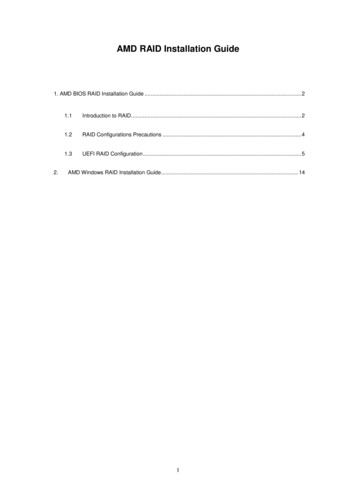
1.3 Motherboard Layout123456789101112131415161718CPU Fan Connector (CPU FAN2)Power Fan Connector (PWR FAN1)CPU Fan Connector (CPU FAN1)ATX 12V Power Connector (ATX12V1)1155-Pin CPU Socket2 x 240-pin DDR3 DIMM Slots(DDR3 A1, DDR3 B1, Black)2 x 240-pin DDR3 DIMM Slots(DDR3 A2, DDR3 B2, Black)ATX Power Connector (ATXPWR1)USB 3.0 Header (USB3 12 13, Black)Intel Z77 ChipsetSPI Flash Memory (64Mb)SATA3 Connectors (SATA3 A0 A1, Gray)SATA3 Connectors (SATA3 0 1, Gray)SATA2 Connectors (SATA2 2 3, Black)Clear CMOS Jumper (CLRCMOS1)Chassis Speaker Header (SPEAKER1, Black)Power LED Header (PLED1)System Panel Header (PANEL1, Black)131920212223242526272829303132333435Infrared Module Header (IR1)SATA2 Connector (SATA2 5, Black)SATA2 Connector (SATA2 4, Black)Chassis Fan Connector (CHA FAN1)USB 2.0 Header (USB 10 11, Black)USB 2.0 Header (USB 8 9, Black)USB 2.0 Header (USB 6 7, Black)Consumer Infrared Module Header(CIR1, Gray)COM Port Header (COM1)Print Port Header (LPT1)PCI Express 2.0 x16 Slot (PCIE4, Black)PCI Express 3.0 x16 Slot (PCIE3, Black)PCI Express 2.0 x1 Slot (PCIE2, Black)PCI Express 3.0 x16 Slot (PCIE1, Black)Front Panel Audio Header(HD AUDIO1, Black)HDMI SPDIF Header(HDMI SPDIF1, Black)Chassis Fan Connector (CHA FAN2)
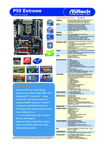
1.4 I/O Panel123*4567** 8USB 2.0 Ports (USB01)D-Sub Port (VGA1)USB 2.0 Ports (USB23)LAN RJ-45 PortCentral / Bass (Orange)Rear Speaker (Black)Line In (Light Blue)Front Speaker (Lime)91011*** 12131415Microphone (Pink)Optical SPDIF Out PortUSB 3.0 Ports (USB45)eSATA3 ConnectorHDMI Port (HDMI1)DVI-D Port (DVI1)PS/2 Keyboard Port (Purple)* There are two LED next to the LAN port. Please refer to the table below for the LAN port LEDindications.LAN Port LED IndicationsActivity/Link LEDStatusDescriptionOffNo LinkBlinking Data ActivityOnLinkACT/LINKLEDSPEED LEDStatusDescriptionOffOrangeGreen10Mbps connection100Mbps connection1Gbps connectionSPEEDLEDLAN Port** If you use 2-channel speaker, please connect the speaker’s plug into “Front Speaker Jack”.See the table below for connection details in accordance with the type of speaker you use.TABLE for Audio Output ConnectionAudio Output Channels Front Speaker Rear Speaker(No. 8)(No. 6)2468VVVV-VVV14Central / Bass(No. 5)--VVLine in(No. 7)---V
To enable Multi-Streaming function, you need to connect a front panel audio cable to the frontpanel audio header. After restarting your computer, you will find “Mixer” tool on your system.Please select “Mixer ToolBox”, click “Enable playback multi-streaming”, and click“ok”. Choose “2CH”, “4CH”, “6CH”, or “8CH” and then you are allowed to select “Realtek HDAPrimary output” to use Rear Speaker, Central/Bass, and Front Speaker, or select “RealtekHDA Audio 2nd output” to use front panel audio.*** eSATA3 connector supports SATA Gen3 in cable 1M.15
Chapter 2: InstallationThis is a micro ATX form factor (9.6" x 9.6", 24.4 x 24.4 cm) motherboard. Beforeyou install the motherboard, study the configuration of your chassis to ensure thatthe motherboard fits into it.Make sure to unplug the power cord before installing or removing themotherboard. Failure to do so may cause physical injuries to you anddamages to motherboard components.2.1 Screw HolesPlace screws into the holes indicated by circles to secure the motherboard to thechassis.Do not over-tighten the screws! Doing so may damage the motherboard.2.2 Pre-installation PrecautionsTake note of the following precautions before you install motherboard componentsor change any motherboard settings.1.2.3.4.5.Unplug the power cord from the wall socket before touching anycomponents.To avoid damaging the motherboard’s components due to staticelectricity, NEVER place your motherboard directly on the carpetor the like. Also remember to use a grounded wrist strap or touch asafety grounded object before you handle the components.Hold components by the edges and do not touch the ICs.Whenever you uninstall any component, place it on a grounded antistatic pad or in the bag that comes with the component.When placing screws into the screw holes to secure the motherboard to the chassis, please do not over-tighten the screws! Doingso may damage the motherboard.Before you install or remove any component, ensure that the power isswitched off or the power cord is detached from the power supply. Failure to doso may cause severe damage to the motherboard, peripherals, and/orcomponents.16
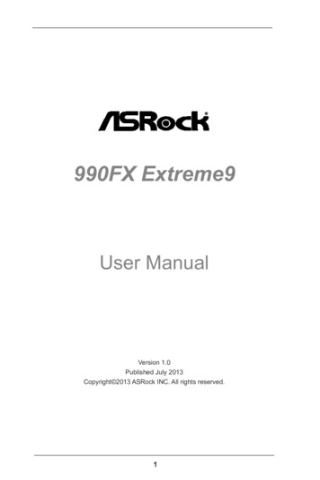
2.3 CPU InstallationIn order to provide the LGA 1155 CPU sockets more protection and make the installation process easier, ASRock has addeda new protection cover on top of the loadplate to replace the former PnP caps thatwere under the load plate. For the installation of Intel 1155-Pin CPUs with the newprotection cover, please follow the stepsbelow.1155-Pin Socket OverviewBefore you insert the 1155-Pin CPU into the socket, please check if theCPU surface is unclean or if there are any bent pins in the socket. Donot force to insert the CPU into the socket if above situation is found.Otherwise, the CPU will be seriously damaged.Step 1.Open the socket:Step 1-1. Disengage the lever by pressing itdown and sliding it out of the hook.You do not have to remove the protection cover.Step 1-2. Keep the lever positioned at about135 degrees in order to flip up theload plate.Step 2.Step 2-2. Orient the CPU with the IHS (Integrated Heat Sink) up. Locate Pin1and the two orientation key notches.17black lineInsert the 1155-Pin CPU:Step 2-1. Hold the CPU by the edge which ismarked with a black line.
orientation key notchalignment keyPin1Pin1alignment key1155-Pin Socketorientation key notch1155-Pin CPUFor proper installation, please ensure to match the two orientationkey notches of the CPU with the two alignment keys of the socket.Step 2-3. Carefully place the CPU into thesocket.Step 2-4. Verify that the CPU is within the socket and properly mated to the orientkeys.Step 3.Close the socket:Step 3-1. Flip the load plate onto the IHS.Step 3-2. Press down the load lever, and secure it with the load plate tab underthe retention tab. The protectioncover will automatically come off byitself.Please save and replace the cover if the processor is removed. Thecover must be placed if you wish to return the motherboard for afterservice.18
2.4 Installation of CPU Fan and HeatsinkThis motherboard is equipped with 1155-Pin socket that supports Intel 1155-PinCPUs. Please adopt the type of heatsink and cooling fan compliant with Intel 1155Pin CPU to dissipate heat. Before you install the heatsink, you need to spray thermal interface material between the CPU and the heatsink to improve heat dissipation. Ensure that the CPU and the heatsink are securely fastened and in good contact with each other. Then connect the CPU fan to the CPU FAN connector (CPUFAN1, see page 13, No. 3 or CPU FAN2, see page 13. No. 1).For proper installation, please kindly refer to the instruction manuals of yourCPU fan and heatsink.Below is an example to illustrate the installation of the heatsink for 1155-Pin CPUs.Step 1. Apply thermal interface material onto the center of the IHS on the socket’s surface.Step 2.Step 3.Step 4.Place the heatsink onto the socket. Ensurethat the fan cables are oriented on side closestto the CPU fan connector on the motherboard(CPU FAN1, see page 13, No. 3 or CPUFAN2, see page 13. No. 1).Align fasteners with the motherboard throughholes.Rotate the fastener clockwise, then pressdown on fastener caps with thumb to installa
Memory - Dual Channel DDR3 Memory Technology (see CAUTION 2) - 4 x DDR3 DIMM slots . 1600/1333/1066 non-ECC, un-buffered memory - Max. capacity of system memory: 32GB (see CAUTION 3) - Supports Intel Extreme Memory Profile (XMP)1.3/1.2 Expansion Slot - 2 x PCI Express 3.0 x16 slots (PCIE1/PCIE3: single at x16 (PCIE1) / x8 (PCIE3) or dual at .