Transcription
PRODUCTMANUALBAT CDMASKU: IPD-BAT-CDMACellular & Internet Alarm Communicatorwww.ipdatatel.com
Technical Support InformationFor Technical Support, call toll free: 866-896-2944Email: techsupport@ipdatatel.comWeb: www.ipdatatel.comipDatatel, LLC13110 Southwest FreewaySugar Land, TX 77478Toll Free: 866-896-2944Revision NotesRevision12.12.2NotesInitial ReleaseIncluded Instructions for bothEthernet/CDMA Firmware Upgrade aswell as CDMA provisioning.Fixed minor programming instructionsCellular BAT –CDMA Installation Guide Rev. 2.2Date4/29/20135/23/20138/13/20132
QUICK REFERENCESee Supported Panels section page 23GE:See page 18for detailsProgramming on GE NetworX:SectionCellular BAT-CDMA as Sole CommunicatorDevice 0Location 0Enter the Phone NumberLocation 1Enter Account NumberLocation 2Enter ‘13’ for Contact IDVISTA:See page 15for detailsProgramming on Vista:SectionCellular BAT-CDMA as Sole Communicator41Enter Phone Number43Enter Account Number193Enter 1, 0. Enable to turn on Address 20DSC:See page 11for detailsProgramming on DSC:SectionCellular BAT-CDMA as Sole Communicator301Enter Phone Number310Enter Account Number350Enter ‘03’ for Contact IDCellular BAT –CDMA Installation Guide Rev. 2.23
Table of ContentsTechnical Support Information . 2Revision Notes . 2Introduction . 5Key Features . 5Broadband Internet Connectivity . 5Cellular BAT-CDMA Internet Connectivity . 6Remote Universal Downloader . 6Virtual Keypad Access . 6Alarm Notifications via Text and Email . 6Computerized Voice Alarm Notifications . 7Tamper Switch Monitoring. 7Installation Guide . 7CDMA Service Provisioning . 7General Considerations . 8Pre-Installation . 8Locating and Installing the Cellular BAT-CDMA . 9Telco - Digital Dialer . 9Virtual Keypad Connection . 9Power Connection . 9Basic Programming . 9Full Virtual Keypad Programming. 10Troubleshooting Diagnostic Information . 10Validating the Installation . 10Wiring & Programming for Popular Panels . 10DSC Panel Wiring and Programming . 11Vista Panel Wiring and Programming . 15GE Panel Wiring and Programming . 18Generic Alarm Panel Wiring and Programming . 20Generic Keyswitch Wiring and Programming . 21Supported Panels . 23Firmware Upgrade Instructions . 25Firmware Upgrade via Ethernet . 25Firmware Upgrade via Cellular . 26Warranty Information . 28FCC and Industry Canada Regulatory Compliance . 29Circuit Board Details . 31Specifications . 32Troubleshooting Diagnostic Information . 32Cellular BAT –CDMA Installation Guide Rev. 2.24
IntroductionipDatatel’s Cellular Broadband Alarm Transceiver - CDMA("Cellular BAT-CDMA" or "Product") is a multi-path Cellular radioand wired internet connected alarm panel transceiver. TheProduct transmits alarms over broadband Internet via hardwiredRJ45 Ethernet connection or via Verizon’s Cellular CDMA network.The Cellular BAT-CDMA is compatible with any alarm controlpanel that transmits Contact ID (CID) format from its digital dialercommunicator. The Product also connects to the Keypad Bus ofcompatible alarm control panels (Honeywell, DSC, and GENetworX) to provide additional interactive services.The end user has virtual keypad access via smartphone and theweb, as well as alarm monitoring notifications via text, email, andcomputerized voice call.ipDatatel’s proprietary uDownloader software enables remotemanagement of Honeywell, DSC, and GE NetworX alarm panelsthat are connected to the Cellular BAT-CDMA, Wifi BAT, and BATproducts.Key FeaturesBroadband Internet ConnectivityThe Cellular BAT-CDMA technology replaces outdatedconventional phone lines to provide high-speed IP alarmmonitoring transmissions over the Internet. By capturing the datatransmission from the alarm control’s digital dialer output, theProduct emulates an alarm receiver.The Product also resolves the communication problems that VOIPservices create that chop up alarm signal transmissions.IP Alarm transmissions are made using Contact ID format and canbe sent to your alarm receiver via landline, or can be transmitteddirectly by IP to your central station.
Alarm monitoring signals such as open/close, trouble, supervisory,latch-key, and monitoring of special devices, can be routed directlyto your alarm monitoring station or to the customer. Theseautomated features of the Product gives you control over whatsignals are sent to the central station, helping save on monitoringcosts.Cellular BAT – CDMA ConnectivityipDatatel’s Cellular BAT-CDMA is a multi-path solution, giving youtwo separate transmission paths to your central station. The alarmpanel can be set up to have hard wired Ethernet connectivity, anda “fail-over” to Cellular radio connectivity, if hard wired connectivityis lost for any reason (power outage, lines cut, etc.) A customermay also wish to run their alarm monitoring using Cellularconnectivity exclusively. This provides for alarm monitoring atalarm sites that lack Internet and/or phone line service.Remote Universal Downloader (uDownloader)ipDatatel’s Universal Downloader software, the “uDownloader,”installs on a Windows Machine in the Service Tray, and enablesremote management of alarm panels that are connected to theCellular BAT-CDMA via the Internet (CDMA or hardwired).uDownloader supports Honeywell Compass, GE NetworX DL900,and DSC DLS IV& DLS 5. The uDownloader software is availablefor download at www.alarmdealer.com in the Dealer Resourcessection.Virtual Keypad AccessYour customers can operate their alarm system using ipDatatel’sSecureSmart app using their smartphone, or web browser. TheSecureSmart gives the customer a virtual keypad to their alarmpanel, and provides a quick connection time. The SecureSmart isvery useful for quick and convenient arming and disarming as wellas periodic alarm history checks. SecureSmart is compatible withiPhone and Android platforms, and is free to download at the AppStore or the Google Play Store – Search for “SecureSmart”. Thevirtual keypad is also available as a web application onalarmdealer.com that runs from any Internet connected browser.Alarm Notifications via Text and EmailThe Cellular BAT-CDMA also provides notifications for alarm,supervisory, trouble, and open/close signals. Notifications by textCellular BAT –CDMA Installation Guide Rev. 2.26
and email identify the alarm system address, alarm signal andzone, and description.Computerized Voice Alarm NotificationsipDatatel also provides an exclusive feature of notifications viacomputerized voice for customers who wish a phone call, wherethey may not want text or email messages.Tamper Switch MonitoringThe Cellular BAT-CDMA provides a tamper switch that is activatedwith the plastic enclosure on the device is opened. This allows anevent/alarm to be tracked and or reported, based on yourcompany’s policies.Installation GuideCDMA Service ProvisioningOverviewThe Cellular BAT-CDMA module requires it be registered withVerizon and an Over The Air Service Provisioning (OTASP) becompleted. During an OTASP the Product module obtains an IPaddress with the nearest cell tower and provides IP connectivity tothe device.ResolutionThese steps will provision the Product with the Verizon network forconnectivity.Service Provisioning Steps1.2.3.4.5.To begin, ensure that the board is powered appropriately with12Volts either from a battery or the Customer Control Panel.Press and release the SW1 switch 3 times (I.E. triple click theswitch)Once released, the unit will auto power cycle. When it reinitializes you should see LEDs 3 – 6 scrollingOnce acquired into the network, you will see the signal strengthindicated on the board via LEDs 3 – 6.Wait approximately 5 minutes before sending signals.Cellular BAT –CDMA Installation Guide Rev. 2.27
General Considerations Before installation, your Cellular BAT-CDMA must also be setupusing the dealer Branded Portal www.alarmdealer.com.The Product should be installed securely in the supplied plastichousing, and be mounted next to your alarm control panel.Where available, proximity to the hard-wired Ethernet Internetconnection should be taken into consideration when routingwires.Choose a location with good Cellular reception by monitoring theProduct's signal strength LEDs with a pre-wire power up.The Product must be completely powered down before startingthe wire up.Programming is simple using the alarm control panel. Writteninstructions are included in the “Wiring & Programming” sectionof this manual starting on page 10.Pre-InstallationHardware RegistrationBefore installation of your Cellular BAT-CDMA, it must beregistered at www.alarmdealer.com.Here are the steps needed to register your hardware: Log in to alarmdealer.com with the dealer login information thatwas emailed to you.Navigate to ‘Dealer Menu’- ’Hardware Registration’Enter the MAC address for the board you wish to registerAdding a Cellular BAT-CDMA to a Customer AccountAfter registering the hardware, the Product must be added to aCustomer Account. To do this, follow these steps: Log in to alarmdealer.com with the dealer login information thatwas emailed to you.Navigate to ‘Dealer Menu’- ’User Accounts’, then click ‘CreateAccount’Fill in the customer informationClick ‘Add Hardware’Find and select the Product you registered earlier. You cansearch for it by MAC address.Follow other registration steps and options as found on thispage, then click ‘Save’ to complete the registration.Cellular BAT –CDMA Installation Guide Rev. 2.28
Locating and Installing the Cellular BAT-CDMAThe Product connects to the alarm panel’s power connections,Telco, virtual keypad bus (if available), and keyswitch connections(optional).The Cellular BAT-CDMA should be connected to the Internet via ahard-wired (RJ45) internet connection located on the lower-righthand side to the circuit board. If a hard-wired Internet connectionis not available then the Cellular connection will be used. TheProduct automatically seeks an IP address. There is no need toprogram routers or switches.Telco - Digital DialerThe Cellular BAT-CDMA‘s signal collection expects Contact IDformat from the digital dialer on the alarm panel. Most controlpanels made in the last decade are capable of this. Wire the Telcoside of the alarm control's Tip & Ring to the Product's Tip & Ring.Virtual Keypad ConnectionThe Cellular BAT-CDMA connects to most panels as a VirtualKeypad, allowing the customer full virtual keypad access after theyauthenticate using the customer username and password youhave assigned them in the pre-installation phase. This allows thecustomer to use our SecureSmart mobile phone and webinterfaces. You will need to refer to the wiring diagram for yourspecific panel because the panel side the Virtual Keypadconnection has various labels (Data in-Data out, YEL-GRN, or justData). This connects to the G/RX, Y/TX connections on theProduct.Power ConnectionThe last step is to wire the alarm panel’s 12VDC auxiliary powerand ground to Product's positive (pin 3) and negative (pin 4)terminals. See Illustration on page 31.Basic ProgrammingBecause the Cellular BAT-CDMA simulates telephone service tothe panel, general programming for the control is limited toconfiguring the signal format as Contact ID, as well as inputting atelephone number to dial. In our case the actual telephone numberdoes NOT matter and is NOT used in the signal delivery process.Cellular BAT –CDMA Installation Guide Rev. 2.29
Full Virtual Keypad ProgrammingFor panels that are “Interactive Ready” (See Supported Panelssection page 23) the following programming will give you full virtualkeypad access to where the customer can enter their 4 digit codeto arm & disarm the system, when using SecureSmart mobile andweb interfaces.DSC Panels: No programming required to make the virtual keypadoperate.GE Panels: Enter & Exit programming, Cellular BAT-CDMA willenroll as a Keypad (240) in the panel.Honeywell Vista Panels: Enable *193 with (1,0) to turn on Address20.Troubleshooting Diagnostic InformationUnder normal operation the Activity light will periodically blink. Apower cycle is recommended if the Activity light is not periodicallyblinking.Validating the InstallationAfter the unit is properly connected to the Alarm Panel andpowered up, use the following steps to validate that the system isfunctioning properly: Ensure that virtual keypad functionality works throughalarmdealer.com, or the SecureSmart mobile app.Ensure that alarm signals reach your central station.Wiring & Programming for Popular PanelsThe following pages are organized by Alarm Panel type. Wiringand programming instructions are given for: Digital Security Control (DSC) Alarm PanelsAdemco & Honeywell Vista Alarm PanelsGE NetworX Alarm PanelsCellular BAT –CDMA Installation Guide Rev. 2.210
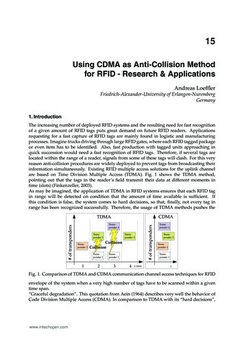
DSC Panel Wiring and ProgrammingDSC ControlPanelRED BLKYEL GRNRING TIPBAT-CDMA16Z2 out15Z1 out14131211109RXDPC-LinkTXDARS-485B7RxRS-232Tx6G / Rx5Y / Tx43- NegPower Pos2Ring1Tip8DSC Keybus & Tip/Ring WiringCellular BAT –CDMA Installation Guide Rev. 2.211
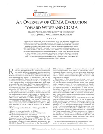
DSC PC-Link connectionThis allows for remote downloader functionality with ipDatatel’sUniversal Downloader (uDownloader) software. (Not Required)DSC PC-Link WiringR Wire Terminal 11B Wire Terminal 12G & W Terminal 4DSCPC-LinkBAT-CDMA16Z2 out15Z1 out14131211109RXDPC-LinkTXDARS-485B7RxRS-232Tx6G / Rx5Y / Tx43- NegPower Pos2Ring1Tip8Cellular BAT –CDMA Installation Guide Rev. 2.212
DSC Panel ProgrammingSee Supported Panels section on page 23. Perform the TELCOProgramming if Tip & Ring is being used. If for whatever reasonyou cannot use Tip & Ring to send Signals then you can wire aPC-Link from the Product to the Panel and perform PC-LinkProgramming. Otherwise, ALWAYS do TELCO Programming.TELCO Programming: General Concept Programming on DSC(Cellular BAT-CDMA as Sole Communicator):SectionAs Sole CommunicatorCode Summarization301Enter a Receiver Number310Enter Account Number350Enter ‘03’ to send Contact ID Panel default is ‘04’, SIANote: Ensure All Report Codes are in, and signals can be sent.PC-Link Programming: DSC Programming for Communications GSM Emulation: If GSM is used, it must be in dialer capture mode.SecCellular BATas SoleCommunicatorCellular BATas Failover w/Add'lCommunication Device015DisableOption 7167Set ‘060’SecondsIf GSM, DisableOption 7If Phone Line,Enable Option 7Set ‘060’SecondsCellular BATas DualReporting w/Add'lCommunication DeviceIf GSM, DisableOption 7If Phone Line,Enable Option 7Set ‘060’Seconds301Set 'CAAF'Set 'CAAF'Set 'CAAF'302N/AN/A303N/A350Set ‘04’ / ‘04’Set 'CentralStation Receiver#'Set ‘04’ / ’03 forContact ID, 04for SIA FSK’ **Set 'CentralStation Receiver#'Set 'CentralStation Receiver#'Set ‘04’ / ’03 forContact ID, 04for SAI FSK’ **CodeSummarizationOption 7 turns on/offtelephone linesupervision.Sets T-Linkacknowledgementdelay to 60 secs.'CAAF' has to be setfor the panel to sendsignals to the PCLinkSecond telephonenumber goes here.This section is thetelephone backup ofsection 301.Format sent aseither contact ID(03), or SIA FSK(04). The PC-Link /BAT can ONLYreceive signals viaSIA FSK (04).Continued on next page.Cellular BAT –CDMA Installation Guide Rev. 2.213
PC-Link Programming: DSC Programming for Communications(GSM Emulation): If GSM is used, it must be in dialer capturemode.SecCellularBAT as SoleCommunicatorEnableOption 1CellularBAT asFailover w/Add'l CommunicationDeviceEnableOption 1, 5CellularBAT as DualReporting w/Add'l CommunicationDeviceEnableOption 1, 2, 5351359EnableOption 1EnableOption 1, 5EnableOption 1, 2, 5367EnableOption 1EnableOption 1, 5EnableOption 1, 2, 5375EnableOption 1EnableOption 1, 5EnableOption 1, 2, 5376EnableOption 1EnableOption 1, 5EnableOption 1, 2, 5380EnableOption 1EnableOption 1, 5EnableOption 1, 5381DisableOption 3,EnableOption 5DisableOption 3,EnableOption 5, 6DisableOption 3,EnableOption 5, 6382EnableOption 5EnableOption 5EnableOption 5389Set ‘003’SecondsSet ‘003’SecondsSet ‘003’SecondsCode SummarizationOptions to turn on/offalarm/restore fortelephone 1 (option 1),telephone 2 (option 2), andalternate communications(option 5).Options to turn on/offtamper/restore fortelephone 1 (option 1),telephone 2 (option 2), andalternate communications(option 5).Options to turn on/offopening/closing fortelephone 1 (option 1),telephone 2 (option 2), andalternate communications(option 5)Options to turn on/offmaintenance for telephone1 (option 1), telephone 2(option 2), and alternatecommunications (option 5)Options to turn on/offtesting for telephone 1(option 1), telephone 2(option 2), and alternatecommunications (option 5)Option 1 turns on/offcommunications. Option 5turns on/off 3rd phonenumber.Option 3 turns on/off codereporting. Options 5 & 6turns on/offcommunication with phonelines 1/3 & 2 respectively.Option 5 enables/disablesT-Link/PC-Link.The time it will take toperiodically check forfaults on the T-Link/PCLink.Cellular BAT –CDMA Installation Guide Rev. 2.214
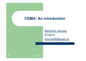
Honeywell Vista Panel Wiring and ProgrammingVista Control Panel -Data DatainoutTIP RINGBAT-CDMA16Z2 out15Z1 out14131211109RXDPC-LinkTXDARS-485B7RxRS-232Tx6G / Rx5Y / Tx43- NegPower Pos2Ring1Tip8Vista Keybus & Tip & Ring WiringCellular BAT –CDMA Installation Guide Rev. 2.215
Honeywell Vista Panel ProgrammingSee Supported Panels section on page 23. Perform the TELCOProgramming if Tip & Ring is being used. If for whatever reasonyou cannot use Tip & Ring to send Signals then you can performECP Bus Programming. Otherwise, ALWAYS do TELCOProgramming.TELCO Programming: Programming on Vista (BAT as SoleCommunicator):SectionCellular BAT as SoleCommunicator414349Enter Phone NumberEnter Account NumberEnter 554Enter 055Enter 065 & 66Enter 1193Enter 1, 0Code SummarizationFor All Communicationsto BATNo Delay BetweenCommunicatorsPhone LineCommunicates FirstIf you wantOpening/Closing ReportsEnable to turn onAddress 20Cellular BAT –CDMA Installation Guide Rev. 2.216
ECP Bus Programming: Vista Programming for Communications- GSM Emulation:SecCellular BAT inCellular BATuse with anotheras SoleCommunicationCommunicator Device forFailoverFor DualReportingCodeSummarization*29Enter 1Enter 1Enter 1This enables GSM.The BAT Emulates aGSM.*42N/AEnter CentralStation ReceiverNumberEnter CentralStation ReceiverNumberSecondary PhoneNumber*43Enter AccountNumberEnter AccountNumberEnter AccountNumberThis is the centralstation accountnumber*49Enter 5Please refer topanel manual foryour particularapplicationrequirementsPlease refer topanel manual foryour particularapplicationrequirementsDual Reporting;Setting to 5 sends allreporting to bothprimary andsecondary.*54Enter 0Enter 2Enter 0The time it takes forthe communicator toswitch from primaryto secondary.*55Enter 1Enter 1Enter 1 (BAT isPrimaryCommunicator)Setting to 1 givessignal priority toGSM (BAT).*65Enter 1Enter 1Enter 1Report Code forOpenings.*66Enter 1, 1Enter 1, 1Enter 1, 1Report Code forArming in Away andStay.*193Enter 1, 0Enter 1, 0Enter 1, 01 turns on/off keypadaddress. 0 setssound to beep.See Supported Panels section on page 23 to verify your panel’srevision number and GSM emulation programming.Cellular BAT –CDMA Installation Guide Rev. 2.217
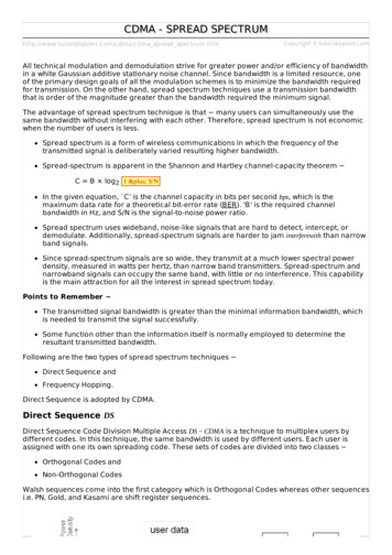
GE Panel Wiring and ProgrammingGE Control PanelPosCom DataTRBAT-CDMA16Z2 out15Z1 out14131211109RXDPC-LinkTXDARS-485B7RxRS-232Tx6G / Rx5Y / Tx43- NegPower Pos2Ring1Tip8GE Keybus & Tip & Ring WiringCellular BAT –CDMA Installation Guide Rev. 2.218
GE Panel ProgrammingSee Supported Panels section on page 23.Recommended: General Concept Programming on GE NetworX:SectionBAT as Sole CommunicatorDevice 0,Location 0Device 0,Location 1Device 0,Location 2Enter the Phone NumberCode SummarizationEnter Account NumberEnter ‘13’ RecommendedvalueContact IDProgramming for Communications (GSM Emulation):As with existing devices in the NetworX family, the BAT isautomatically enrolled with the control panel when the panel exitsprogramming mode.The Cellular BAT-CDMA registers as a keypad and acommunications device on addresses 240 and 76, respectively. Allsignals are read directly from the panel memory, so any calldirections and/or reporting codes programmed are specifically forother communication devices, such as the panel dialer.For Central Station monitoring, the Account Number for thecustomer MUST be entered into alarmdealer.com. If this is notdone, all alarm signals sent to the Central Station will arrive withan incorrect account number attached. The Cellular BAT-CDMAmust be power-cycled after making this change.To have this enabled so the Cellular BAT-CDMA gets signalsfrom the key bus, you must contact ipDatatel. Otherwise usethe TELCO to send signals.Cellular BAT –CDMA Installation Guide Rev. 2.219
Generic Alarm Panel Wiring and ProgrammingGeneric ControlPanelTelco SideTIP RINGRed Black -BAT-CDMA16Z2 out15Z1 out14131211109RXDPC-LinkTXDARS-485B7RxRS-232Tx6G / Rx5Y / Tx43- NegPower Pos2Ring1Tip8Generic Keypad Bus Tip & Ring WiringGeneric Alarm Panel Programming Program the panel Phone Number into the panelProgram the Customer Account Number into the panelProgram Reporting codes into the panelProgram panel to transmit in Contact ID formatCellular BAT –CDMA Installation Guide Rev. 2.220
Generic Keyswitch Wiring and ProgrammingFor basic keyswitch interactive services with the Cellular BATCDMA, the following alarm panel wiring is needed. A programmable output on the alarm panel will be used to signalto the Product (Y/Tx terminal) that the panel has enteredArm/Disarmed State.The Z1 output on the Product will be used as a key switchconnecting to a ‘zone’ terminal on the alarm panel.Generic Panel –Keyswitch Wiring -PGMZ1Z2Z3BAT-CDMA16Z2 out15Z1 out14131211109RXDPC-LinkTXDARS-485B7RxRS-232Tx6G / Rx5Y / Tx43- NegPower Pos2Ring1Tip8Cellular BAT –CDMA Installation Guide Rev. 2.221
Generic Keyswitch ProgrammingKeyswitch state programming examples for Ademco, DigitalSecurity Controls, and GE NetworX for Keyswitch and panel stateprogram output operations are given below.Most alarm panel manufacturers will have the capability toconfigure a zone as a keyswitch and generally have at least oneon-board programmable output that can be configured to activateon a number of different control state conditions. Reference thealarm panel installation manual for details on your specificinstallation.Ademco/Honeywell Vista (General Concept)56 program zone as type 7780 Menu LED OutsProgram 17 and 18 zone type 78 and 79DSC PowerSeries (General Concept)Program zone as '22'PGM Output '6'DSC Alexor (General Concept)Wiring:Y/Tx - I/01G/Rx - I/026.2k ohms resistor from - Y/TxProgramming:Section 009 - '06'/'22'Section 013 - Enable 2 & Disable 1Section 134 - Enable 14 (Press 9, then 6) This makes it normallyclosed.Section 501 - Enable 3GE NetworX (General Concept)Program zone as '11'LED StatusLocation 47 Segment 1: 21Location 47 Segment 2: 0Cellular BAT –CDMA Installation Guide Rev. 2.222
Supported PanelsAdemco / Honeywell VistaPanelRevisionDigital FullGSMDialer Interactive EmulatorVista-10P2.6 Vista-10PSIA4.0 Vista-128BP3.0 Vista-128BPE1.0 Vista-128FB1.0 Vista-128FBP2.0 Vista-128FBPE1.0 Vista-128SIA2008 Vista-152 Vista-15CN2.6 Vista-15P2.6 Vista-15PCN2.6 Vista-15PSIA4.0 Vista-20P2.6 Vista-20PCN2.6 Vista-20PI5 Vista-20PS2.6 Vista-20PSIA4.0 Vista-21IP1.0 Vista-21IPSIA1.0 Vista-32FB1.0 Cellular BAT –CDMA Installation Guide Rev. 2.223
First Alert FA130 2.6 First Alert FA148 2.6 First Alert FA168 2.6 ADT Safewatch2.6 Pro 3000/3000EN DSC (Digital Security Control)PanelRevisionDigital FullGSMDialer Interactive EmulatorPC5010Any PC16164.13 PC18324.13 PC18644.13 AlexorALL GE NetworXPanelRevisionDigital FullGSMDialer Interactive EmulatorNX-4V2 V2 NX-6V2 V2 NX-8V2 V2 Cellular BAT –CDMA Installation Guide Rev. 2.224
For non-supported panels: Bridge 12 VDC to "Y/TX" Terminalwith any type of radial resistor with a value of 2.7k to 10k as aweak "pull up".Note: Any Control Panel NOT on this list is supported as long as itprovides Tip & Ring and transmits Contact ID. If the panel has theability to use a Dedicated Open Zone that acts as a Keyswitch,you can Arm/Disarm from the Website or Mobile Phone.Firmware Upgrade InstructionsFirmware Upgrade via EthernetOverviewFor Board manufactured prior to May 2013 (with firmware versionprior to 000F), it is STRONGLY recommended that Firmwareupgrades are accomplished via Ethernet.Check the MAC address / date sticker on your Product board. Ifthere is no date printed or the date is before May 2013, then thisupgrade procedure is recommended in order to ensure that futureOver-the-Air Firmware upgrades will be successful.ResolutionThese steps will upgrade the firmware on the Cellular BAT-CDMAwhile connected to an Ethernet network.Firmware Upgrade Steps1. Connect the Ethernet port to an Internet router.2. Once you have provided the board an Internetconnection, the unit must be powered using a 12 Voltpower source.a. NOTE: Please ensure to connect the positivelead of the power supply to pin 3 of the boardand the negative lead of the power supply to pin4 of the board.3. Call the ipDatatel Network Operations Center (toll free at866-896-2944) with the MAC Address located on the faceof the unit.4. ipDatatel’s Network Operations Center will push firmwareimmediately to the device remotely this will takeanywhere from 2 to 3 minutes.Cellular BAT –CDMA Installation Guide Rev. 2.225
5.6.7.Upon completion of remote upgrade the unit willautomatically restart. Do not unplug the BAT unit itsreboot has completed.Once reboot has completed, LED1 (Status) will blink 5times.Once the BAT has rebooted, the board will display theservice bars denoting tower connectivity strength.Firmware Upgrade via Cellular BAT-CDMAOverviewFor boards with Firmware version 000F or later, it is possible toupgrade the remote equipment using the Product module.To confirm the date of manufacture, please refer to the MACaddress / date sticker on the Product board. If there is no dateprinted or the date is before May 2013, then this upgradeprocedure is NOT recommended.ResolutionThese steps will upgrade the firmware on the Cellular BAT-CDMAwhile connected to an Ethernet network.Firmware Upgrade Steps1. Power on the Product with a 12V power source (eitherthrough a battery or a control panel).a. NOTE: Please ensure to connect the positivelead of the power supply to pin 3 of the boardand the negative lead of the power supply to pin4 of the board.2. Ensure that CDMA Service Provisioning has beenaccomplished and that the Product module is active andin-network. If unsure, please contact the ipDatatelNetwork Operations Center with the MAC addresslocated on the face of the unit.3. ipDatatel’s Network Operations Center can push firmwareimmediately to the device remotely this can takeanywhere from 20 to 30 minutes, depending onconnectivity.4. Upon completion of remote upgrade the unit willautomatically restart. Do not unplug the Product.26Cellular BAT –CDMA Installation Guide Rev. 2.2
5.6.Once reboot has complet
The Cellular BAT-CDMA's signal collection expects Contact ID format from the digital dialer on the alarm panel. Most control panels made in the last decade are capable of this. Wire the Telco side of the alarm control's Tip & Ring to the Product's Tip & Ring. Virtual Keypad Connection The Cellular BAT-CDMA connects to most panels as a Virtual