Transcription
RESEARCH ARTICLEInvestigation of Compression Strength of BlissStyle Corrugated Fiberboard BoxesJavier de la Fuente*California Polytechnic State UniversityPREFACE API 2015Jay SinghCalifornia Polytechnic State UniversityRebecca KischCalifornia Polytechnic State UniversitySoma RoyCalifornia Polytechnic State UniversityDaan PelemanKatholieke Universiteit LeuvenABSTRACTThe global demand for corrugated fiberboard is projected to experience a significant upsurge in the near future.Based on the end-use, packaging for processed and fresh food categories accounted for approximately 39% of theoverall consumption of corrugated fiberboard in 2015. With key advantages such as providing an uninterruptedbottom, laminated corners for higher stacking strength, increased material use efficiency, side cutout options fordisplay at retail and a wide range of styles over other styles of containers, Bliss style boxes find prominence inthe agriculture sector. While numerous predictive strength models associating corrugated fiberboard materialspecifications to the box compression strength (BCT), and ultimately the stacking strength of corrugatedcontainers, have been developed over the past century, there is a considerable lack of studies that include Blissstyle containers. The overall aim of this empirical study was to develop a mathematical relationship based onthe simplified McKee formula towards predicting BCT of four styles of Bliss boxes. Effects of box styles, length ofload-bearing walls and number of internal corners on the overall BCT were explored using data collected fromlab-based testing. The proposed mathematical model includes a box design constant (k), edge crush test values,board thickness, and three lengths of load-bearing walls (total, single-wall, and double-wall) of the containers.The k-values for each bliss box design, explored through linear regression analyses, explain up to 98.1% ofthe differences in BCT between the styles. The proposed mathematical model can assist practitioners withaccelerating packaging development cycle times and optimizing packaging designs.KEY WORDSCorrugated Fiberboard, Bliss Boxes, Box Compression Strength, McKee Formula, Mathematical Model*Javier de la FuenteCorresponding Authorjdelafue@calpoly.eduJournal of Applied Packaging Research 45
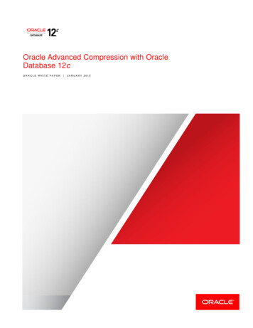
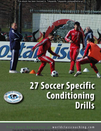
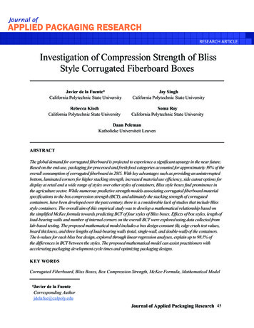
INTRODUCTIONDriven by an anticipated increase in near futuredemand, the global corrugated fiberboard industry isforecast to reach a market size of 336.26 billion by2023. Increasing from 268.50 billion in 2017, thisrepresents a compound annual growth rate of 3.82 %[1]. The key drivers of this increased demand of corrugated fiberboard includes significant investmentsin environmental protection and energy optimizationprograms by producers, increased “right-weighting”(light-weighting) solution initiatives, rapidly evolvinge-commerce business, surge in digital (interactive)print options for traditional and e-commerce packaging, demand for more recyclability in containerboardstocks and industry consolidation [2].Based on the end-use, this corrugated packaging market can be divided into the followingsectors: processed food, fresh food and produce,beverages, personal and household care, chemicals, paper products, electrical goods, glasswareand ceramics, tobacco, etc. (Figure 1). “Processedfood” and “Fresh food and produce” accounted fora market share of approximately 39 % in 2015 andare projected to continue their dominance duringthe forecast period 2016-2021 [3].The most common styles of corrugated fiberboard forms can be categorized as slotted boxes, telescope boxes, folders, rigid boxes (e.g., bliss boxes),self-erecting boxes and interior forms (Figure 2) [4].The construction, as well as applications of thesestyles, vary. With all four of its vertical edges reinforced, the bliss box provides greater board-usage tostacking-strength ratio than the other styles of corrugated boxes. In comparison with slotted boxes,bliss boxes require less fiberboard since its bottomconsists of a single thickness resulting in flap areareduction. While relatively stronger and material efficient, bliss boxes are constructed with three die-cutpieces which require specialized set-up equipment atthe point of use including hot melt adhesive.Fig. 1: Global consumption of corrugated board packaging by end use, 2015 [3].Investigation of Compression Strength of Bliss Style 46
The three-piece construction of bliss boxesallows for customized board grades to be usedtowards providing optimization between materialusage and strength [7].Fig. 2: Representation of common box stylesand categories [4].Bliss boxes lend themselves to many differentuses and are primary find considerable application inthe agricultural sector for packing fresh fruits and vegetables, dairy, meat and prepared foods. In addition,bliss boxes can be used towards other applicationsthat require higher stacking strength for storage andhandling during their distribution, such as bottledproducts industry and the construction industry [5].Also, explosives, articles of concentrated weight, etcetera can be packed in bliss boxes [6], [7].Bliss-style boxes, while technically consideredas a tray, are unique because they are constructedfrom three pieces of corrugated fiberboard (Figure3). Similar to a tray, the body of the bliss boxes ismade of a single piece of fiberboard forming thebottom, large sides and major flaps on top. Eachend panel, however, is made from a separate pieceof fiberboard that may include minor flaps. Thebottom and larges sides also constitute overlappingflanges into which the end panels are glued towardsattachment with the main body.Fig. 3: Examples of bliss-style boxes.Journal of Applied Packaging Research 47
While Regular Slotted Containers (RSC) are themost commonly used style of corrugated fiberboardcontainers globally, bliss-style boxes provide the following unique opportunities by comparison [8]: Continuous bottom: the uninterrupted bottomprovides a flat surface for the product to reston thereby reducing potential damage resulting from friction (vibration). Laminated corners: Since a bulk of the compressive load is supported by the corners of abox, the reinforcement provided through thelamination of flanges of the main body andend panels improve the stacking strength ofbliss boxes [9]–[12].The CCF standard provides specificationstowards a full size (“5-down”, 40.64 cm x 30.48 cm)and half size (“10-down”, 60.96 cm x 40.64 cm) footprints (Figure 4) [14]. The recommended uniformfootprint dimensions and interstacking features forcorrugated containers facilitate efficient loading,handling, storage and shipment of produce (i.e., freshfruits and vegetables) on standardized GMA pallets(Figure 5). Studies cited by Fibre Box Associationclaim larger payloads, reduced bruising, similarcooling rates and cost savings in annual handlingand long-distance trucking costs for CCF containers as compared to reusable plastic containers [15]. Material efficiency: Due to the ability to construct bliss boxes using varying board gradesresulting in improved stacking strength, theoverall amount of material usage is lowered. Side cutout options: Meet requirements ofdisplay/retail-ready packaging for big-box stores. Wide range of styles: Unlike RSCs, blissboxes can be created in a variety of stylesoptimized for shipping and retail-readydemands of various product categories.While the pallets commonly used for distribution of goods of retail has been standardized by theGrocery Manufacturers Association (GMA) to be101.60 cm x 121.92 cm, the corrugated packagingfootprint for fresh produce varies substantially [13].Towards improving stackability; lowering shippingcosts; improving product protection; driving consistency in production; meeting display and marketing demands of retailers; and promoting the recyclable/renewable benefits of corrugated fiberboard,a Corrugated Common Footprint (CCF) standardhas been established by the industry [14].Fig. 4: (a) Half-size and (b) full-size CorrugatedCommon Footprint (CCF) containers (dimensions in cm).Investigation of Compression Strength of Bliss Style 48
(1)Where,BCT Box compression strength (lb)ECT Edge crush test value of board (lb/in)DMD Machine-direction flexural stiffness (lb in)DCD Cross-direction flexural stiffness (lb in)P Box perimeter (in)Fig. 5: Mixed pallet load constructed using fulland half CCF containers [14].Box Compression Strength ModelsSince the landmark decision reached via thePridham case in 1914, corrugated fiberboard containershave become the preferred shipping container tomove goods in the various distribution strategies [16].Numerous predictive strength models associatingcorrugated fiberboard material specifications to thecompression strength (lab based observation usingstandard methodologies), and ultimately the stackingstrength (field use approximation), of corrugatedcontainers have been developed over the past century[17]–[27]. The numerous currently existing modelsand software towards predicting corrugated board andbox properties range from molecular length scale tounitized loads [28].Most packaging professionals associated with thedevelopment process of protective packaging solutions related to RSC style corrugated fiberboard boxesare familiar with the McKee formula reported in 1963(Equation 1) [24]. It may be noted that this equationapplies only to RSC style boxes having lengths of lessthan three times the width, and a perimeter of lessthan seven times the depth [27], [29].The simplified form of the McKee formula(Equation 2) is most commonly used by practitioners[24]. Since flexural stiffness is not frequently performed, it is substituted with board thickness (t, in). Ithas been observed that the simplified McKee formulaoverestimates the original McKee formula [30].(2)Batelka & Smith (1993) expanded the originalMcKee box compression model (Equation 1) to includebliss boxes and die cut boxes towards improving theprediction accuracy [29]. The modified equation(Equation 3) included the ECT and flexural stiffness (RMS Bending) and added a “depth” term, d.The modified model is claimed to have improved theprediction accuracy for all structures included in thestudy by 68 % and for all structures within the limitingboundaries of the original model by 42 % [29].(3)Where,BCT Box compression strength (lb)ECT Edge crush test value of board (lb/in)DMD Machine-direction flexural stiffness (lb in)DCD Cross-direction flexural stiffness (lb in)W Width of each panel (in)d Box depth (in)Journal of Applied Packaging Research 49
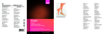
Batelka & Smith provided an example of thepossible application of the modified McKee equationfor a bliss box constructed with two different grades ofcorrugated fiberboard [29]. The total predictive valueof compression strength (BCTT) is calculated usingEquation (4) as the sum of contributions from the body(BCTB) and end panels (BCTE). It may be noted that thispredictive value of the compression strength was notcompared with experimental results in this study.(4)More recently, Ge & Goodwin (2010) developedand reported equations to calculate top-to-bottom andside-to-side compression strengths for FEFCO styles0601 bliss-style cases and 0406 wrap-around styleboxes [27]. Ge & Goodwin’s equation (Equation 5)for predicting bliss-style top-to-bottom compressionstrength is based on the simplified McKee formula andincludes specific mathematical relationships to accountfor the bliss box perimeter and board thickness.(5)Where,BCT Box compression strength (lb)ECT Edge crush test value of board (lb/in)t Board thickness (in)m Manufacturer’s joint width (in)L Box length (in)W Box width (in)Batelka & Smith and Ge & Goodwin’s modelsare well suited to predict compression box strengthof bliss boxes with a standard geometry (i.e., endpanels are rectangular pieces with no creases gluedto the body) but there are other bliss box styles inwhich the cross-sections of the box include creasesand flanges creating triangular columns and edges.These features are known in the industry to increasebox compression strength significantly [31]. Consequently, the overall objective of this study was todevelop a new mathematical relationship based on thesimplified McKee formula that accounted for variations in cross-section geometry of bliss-style boxes.MATERIALS AND METHODSThe methodology used for this investigationincluded the following sequential phases: Measuring compression strength of four different bliss-style boxes of two sizes systematically. Analyzing how design characteristics affectcompression strength in these types of boxes. Developing a mathematical equation based onthe simplified McKee formula that allows predicting box compression strength of bliss-styleboxes with reasonable accuracy and ease. Fitting the mathematical model to theexperimental data.ContainersFour different bliss box designs were included inthis study: standard bliss box (S); standard bliss boxwith internal flanges (SIF); standard bliss box withinternal flanges and diagonal corner (SIFDC); andV-bliss box (V) (Figure 6). Each design of bliss boxwas constructed to meet the full size (“5-down”, 40.64cm x 30.48 cm x 23 cm) and half size (“10-down”,60.96 cm x 40.64 cm x 23) CCF footprints. Lengthof the internal flanges included for SIF, SIFDC, andV designs were 5.08 cm (2 in), 7.62 cm (3 in), 10.16cm (4 in) and 12.70 cm (5 in). 5-down boxes had anapproximate internal volume of 53,101 cm3 (3,240 in3)while 10-down boxes had an approximated internalvolume of 25,425 cm3 (1,552 in3). C-flute corrugatedfiberboard with an ECT value of 3.62 kN/mm (32 lb/in) and caliper of 3.97 mm (0.16 in) was used for theconstruction of all test samples.Investigation of Compression Strength of Bliss Style 50
Boxes were designed using ArtiosCAD software [32] and cut/creased using a Kongsbergtable model 1930 (Esko Graphics, Ludlow, Massachusetts, USA). Each box was identified by uniquecode comprised of four sections as follows:Where,A-B-C-DA Size of the bliss box[5-down 5; 10-down 10]B Bliss box design[S; SIF; SIFDC; V]C D Length of internal flange[0 cm 0; 5.08 cm (in) 2; 7.62 cm (3 in) 3; 10.16 cm (4 in) 4; 12.70 cm (5 in) 5]Replicate number[first 1; second 2; third 3; fourth 4; fifth 5]As an example, “10-SIFDC-4-2” represents“10-down standard bliss box with internal flangesand diagonal corner with a 4-inch (10.16 cm) flangelength and replicate number two.”Compression TestingASTM D642 (Standard Test Method for Determining Compressive Resistance of Shipping Containers, Components, and Unit Loads) was used totest the compression strength [34]. This procedure iscommonly used for measuring the ability of the container to resist external compressive loads applied toits faces, to diagonally opposite edges, or to corners.This test method is also used to compare the characteristics of a given design of container with a standard,or to compare the characteristics of containers differing in construction. This test method is related toTAPPI T804 om-12 [35]. The tests were conductedusing a fixed platen arrangement on a Lansmont compression tester Model 152-30K (Lansmont Corporation, Monterey, CA, USA), with a platen speed of1.3 cm/minute and a pre-load of 22.68 kgf for zerodeflection in accordance with the standard.MethodsDATA ANALYSISConditioningData were analyzed using JMP Pro (Cary,North Carolina, USA) [36] and MATLAB (Natick,Massachusetts, USA) [37]. One-way analyses ofvariance (ANOVA) were carried out to investigatewhether and how box compression strength is relatedto four different bliss-style box designs of two sizes.Linear regression analyses were computed to fitexperimental data to an equation.Prior to all testing, the prototyped boxes were conditioned at standard temperature and humidity (23 1 C and 50 2 % relative humidity) in a walk-in environmental chamber (Darwin Chambers Company,Saint Louis, MO, USA) per ASTM D4332 [33].Fig. 6: Bliss box designs used in the study. Body parts are depicted in gray and end panels in red.Box’s dimensions shown correspond to 10-down sizes.Journal of Applied Packaging Research 51
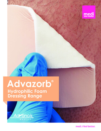
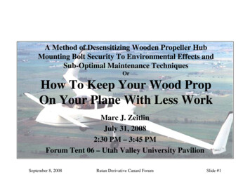
RESULTS AND DISCUSSIONA total of 65 5-down and 55 10-down blissstyle boxes were used in the study. Five attributeswere collected to characterize the geometry ofeach design (Table 1): Box compression strength (BCT) Total length of load-bearing walls (PT), Total length of load-bearing walls using single-wall corrugated board (PSW) Total length of load-bearing walls using double-wall board (PDW) Number of internal corners (C) in the wrapand side components of the box.Effect of Bliss Box Style on BCTFour separate one-way analyses of variancefollowed by Tukey’s HSD multiple comparisontests were performed using JMP Pro. The firsttwo ANOVA examined the nature of differences inaverage BCT for each of the four design styles (i.e.,S, SIF, SIFDC, V) for 10-down and 5-down boxesseparately. Significant differences were identified foraverage BCT of both 10-down boxes (F (3,51) 64.1,p 0.0001)) and 5-down boxes (F (3,61) 116.3, p 0.0001)). Tukey’s HSD post-hoc test was used tomake comparisons between BCT data within 5-downand 10-down boxes. Notably, for both sizes, theaverage BCT of each design style was significantlydifferent from the others (Figure 7).The other two ANOVA analyses examinedthe differences in average BCT for each dimensional variation within the four bliss-styles. Significant differences were identified between dimensional variation with regard to average BCT ofboth 10-down boxes (F (10,44) 38.6, p 0.0001))and 5-down boxes (F (12,52) 110.6, p 0.0001)).Tukey’s HSD post-hoc test was used to make comparisons between BCT data within 5-down and10-down boxes. For 5-down size boxes, this analysisrevealed seven homogenous subsets. For 10-downsize boxes, the analysis revealed nine homogenoussubsets. For both sizes, standard bliss box designs(S-5 and S-10) were significantly different from theother design variations (Figure 8).From the four analyses, it can be seen that, asexpected, BCT increases significantly when the totallength of load-bearing walls increases by addinglength through flanges and by adding triangularcolumns. For both 5-down and 10-down boxes, thefour design styles can be ordered as follows, fromlowest BCT to highest BCT: S, SIF, SFIDC, and V.Effect of Length of Load Bearing Walls on BCTBliss-style boxes comprise of two parts: a bodyand two end panels. As a result, the total length ofload-bearing walls (PT) has sections with singlewall corrugated board and sections with double-wallcorrugated board. This is one of the reasons whythe simplified McKee’s equation (Equation 2) doesnot predict BCT of a bliss box accurately. Figure9 depicts experimental BCT of the four bliss-styleboxes as a function of total length of load-bearingwalls. The cloud of points on the right represents5-down boxes; larger boxes with more wall length.The group of points on the left represents 10-downboxes; smaller boxes with less wall length. The redline on the bottom part of the chart represents BCTpredicted by the simplified McKee’s equation usedfor RSC containers. This equation yields approximated BCT values for the standard bliss box (S) butit underestimates BCT for SIF, SIFDC, and V styles.In a bliss box, single-wall and double-wallload-bearing walls length have an inverse relationship with BCT. As length of walls with single-wallboard (PSW) decreases, the length of walls with double-wall board (PDW) increases and so does BCT.This relationship can be seen in Figure 10.Investigation of Compression Strength of Bliss Style 52
Table 1: Summary of attributes used to characterize each bliss box design.Journal of Applied Packaging Research 53
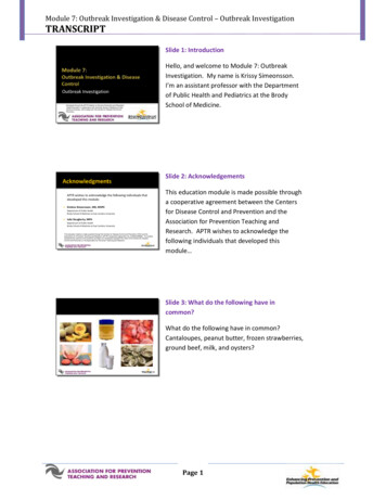
Effect of Number of Internal Corners on BCTIn addition of having sections of load-bearingwalls with single-wall and double-wall corrugatedboard, the transversal cross-sections of the different bliss boxes styles have an increasing number ofinternal corners or angled bends (Figure 11). In the Sbliss-style, the body component of the box forms fourcorners and the end panels do not have any corners(i.e., they are rectangular pieces). In the SIF style,body and ends form four corners each totalizing eightinternal corners. The SIFDC style has four cornersprovided by the body and eight additional cornersprovided by the end panels and their diagonal featurescompleting a total of 12 internal corners.The V style has a total of 18 internal corners.The same 12 corners than the SIFDC style plus sixcorners provided by the triangular columns in themid-part of the sides.Internal corners create vertical edges and triangular columns that can increase box compression strength significantly. This is a very wellknown design strategy used by practitioners inthe corrugated box industry [31]. Figure 12 showshow BCT tends to increase with increased numberof internal corners. Moreover, the relationshipseems to be non-linear.Fig. 7: Box compression strength for the four bliss-style box designs for 10 down (left) and 5-down (right) sizes.Error bars represent standard errors. Levels not connected by the same letter are significantly different.
Fig. 8: Box compression strength for each design variation for (a) 10-down size and (b) 5-down size.Error bars represent standard deviations. Levels not connected by the same letter are significantly different.Journal of Applied Packaging Research 55
Fig. 9: Box compression strength as a function of total length of load-bearing walls of all samples tested.The red line represents BCT calculated using the simplified McKee equation.Fig. 10: Box compression strength as a function of the length of load-bearing walls with single-wall anddouble-wall corrugated boards.Investigation of Compression Strength of Bliss Style 56
Fig. 11: Transversal cross sections of the four bliss-style boxes tested. Body parts are depict-ed in black andend panels in red. Box’s dimensions shown correspond to 10-down sizes.Fig. 12: Box compression strength versus number of internal corners of each bliss-style box tested.Journal of Applied Packaging Research 57
Mathematical ModelIn an attempt to explain the experimental data,we explored several equations and developed one thatpredicts BCT with accuracy and practicality. We proposea mathematical model (Equation 6) based on the simplified version of McKee’s equation (Equation 2) and theanalyses described in the previous sections. The modeltakes into consideration the following variables: The total length of load-bearing walls usingsingle-wall corrugated board. The total length of load-bearing walls usingdouble-wall corrugated board. The total number of internal corners. The ratio between the length of load-bearingwalls using double-wall corrugated boardand the total length of load-bearing walls. The edge crush test value of single-wall corrugated board. The edge crush test value of two single-wallcorrugated boards. The thickness of the corrugated board. A unitless constant that accounts for otherdesign differences.(6)Where,BCT Box compression strength (lb)k Box design constantECTSW Edge crush test value ofsingle-wall board (lb/in)ECTDW Edge crush test value ofsingle-wall board (lb/in)t Board thickness (in)PT Length of load-bearing walls of the box (in)PSW Length of load-bearing wallswith single-wall board (in)Lengthof load-bearing wallsPDW with double-wall board (in)of corners in theC Numbertransversal cross sectionThe experimental data collected used boxes fabricated with one type of board (C flute board). Therefore,the model assumes that the same corrugated board isused for the body and end panels of the bliss box.As body and end panels are glued to formthe bliss box, the ECT value for double-wall wasmeasured using glued and unglued standard testsamples. There were no significant differencesbetween glued and unglued samples. An edgecrush test value of 6.33 kN/mm (56 lb/in) wasused for the sections of load-bearing walls withdouble-wall board (ECTDW).Investigation of Compression Strength of Bliss Style 58
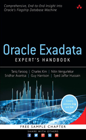
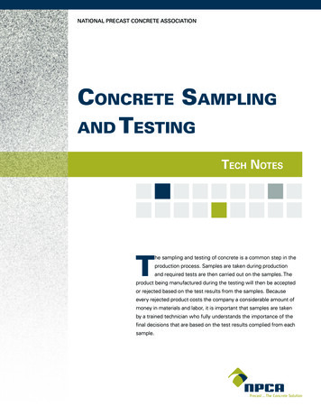
Curve FittingLinear regression analyses for each designstyle were used to fit the experimental data to theproposed model. Experimental data showed that, astotal length of load-bearing walls increases, BCTincreases in a linear fashion (Figure 10). MATLAB software was used to compute iterations and find thek-values for each design style that minimized thesum of squared errors (SSE) between observed andpredicted BCT values (Equation 7):One regression analysis that treated bliss stylesas a block explained about 95.5 % of the differencesof BCT between bliss styles tested (R 2 0.9549). Thisanalysis originated four different k-values (i.e., onefor each design style), they are summarized in Table2. Figure 14 shows how experimental data and modelpredictions are in close agreement for a model withfour k-values constants. A second regression analysiswas run, but this time the combination of design andsize (i.e., 5-down and 10-down) was used as a block.This analysis calculated eight k values (Table 2) andexplained 98.1 % of the differences in BCT betweenbliss styles tested (R 2 0.9811). Figure 15 shows howexperimental data and model predictions are in closeagreement for this model using eight k-values.Fig. 14: (a) Comparison between experimental data andmodel predictions when design style is used as ablock. (b)Corresponding linear regression analysis (R2 0.9549).Table 2: Summary of k-values for each design style and size calculated with two linear regression analyses.Journal of Applied Packaging Research 59
CONCLUSIONS3. Developing a mathematical relationshipbased on the simplified McKee equation.The global corrugated fiberboard industry is experiencing an increased demand [2]. Corrugated packagingfor processed food, fresh food, and produce accountedfor a market share of approximately 39 % in 2015 andare projected to continue their dominance in the immediate future [3]. Slotted boxes, telescope boxes, folders,rigid boxes (i.e., bliss boxes), self-erecting boxes, andinterior forms are the most common styles of corrugatedpackaging [4]. In particular, bliss-style boxes find prominence in the agriculture sector [5]. Their key advantages include providing a continuous bottom, laminatedcorners for higher stacking strength, increased materialuse efficiency, side cutout options for display at retail,and a wide range of styles over other styles of containers.Box compression strength is a critical characteristic for any corrugated box. Minimizing material use andcaliper while maximizing box strength is an importantindustry concern as it can be directly linked to moneysavings by decreasing product loss, material costs,and manufacturing costs. While numerous predictivestrength models [17]–[27] associating corrugated fiberboard material specifications to the box compressionstrength (BCT) and ultimately the stacking strength ofcorrugated containers have been developed over thepast century, there is a considerable lack of studies thatinclude bliss-style containers.The overall aim of this empirical study was todevelop a mathematical relationship for predictingcompression strength of four bliss box styles. Theproject comprised the following phases:4. Fitting the mathematical model to theexperimental data.1. Collecting compression strength data in asystematic manner of four different blissstyle boxes of two sizes were collected2. Performing analyses of how box designcharacteristics affect box compressionstrength.Fig. 15: (a) Comparison between experimentaldata and model predictions when design style andsize are used as a block. (b) Corresponding linearregression analysis (R2 0.9811).Investigation of Compression Strength of Bliss Style 60
Different mathematical equations were exploredand tested. The proposed equation includes the following variables: The total length of load-bearing walls usingsingle-wall corrugated board. The total length of load-bearing walls usingdouble-wall corrugated board. The total number of internal corners. The ratio between the length of load-bearingwalls using double-wall corrugated boardand the total length of load-bearing walls. The edge crush test value of single-wall corrugated board. The edge crush test value of two single-wallcorrugated boards. The thickness of the corrugated board. A unitless constant that accounts for otherdesign differences.Linear regression analyses were used to fit theexperimental data to the proposed model with greataccuracy. One approach considered each bliss styleas a block and yielded a constant k for each of thefour design styles (i.e., S, SIF, SIFDC, V). This modelexplained 95.5 % of the experimental data (R2 0.9549).An alternative approach considered the combinationof bliss box style and size as a block. This analysisyielded eight constants k, one for each design sizecombination (i.e., S-5, S-10, SIF-5, SIF-10, SIFDC-5,SIFDC-10, V-5, V-10). This model explained 98.1 % ofthe experimental data (R2 0.9811).We believe that the first approach provides moreflexibility than the second one as it does not constrainthe user to a size range while having a good fit withrespect to the experimental data. As it can be observedin Table 1, BCT measurements for some of the boxessuch as S-5, SIF-10-5, SIFDC-10-2, SIFDC-10-4, andV-10-3 had high variability (i.e., a coefficient of variation between 10 % and 20 %). Despite these exceptional cases, the model is able to account for morethan 95 % of the observed BCT measurements.The proposed mathematical relationship mayallow practitioners to predict box compression strengthof four different bliss-style boxes with reasonableaccuracy and ease. It has the potential to acceleratepackaging development cycle times and to optimizepackaging design. Further research steps may includeadditional testing to verify the model with more boxsizes and design variations, add
The most common styles of corrugated fiber-board forms can be categorized as slotted boxes, tele - scope boxes, folders, rigid boxes (e.g., bliss boxes), . Fig. 2: Representation of common box styles and categories [4]. Fig. 3: Examples of bliss-style boxes. Investigation of Compression Strength of Bliss Style 48