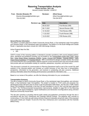
Transcription
Setting up a National Transmission Plan& QoS for International ConnectionsSenior Engineer, TIS – ETSI STQ Vice ChairJoachim POMY
Outline Setting up a National Transmission PlanQoS for International ConnectionsMulti-Vendor EnvironmentIP Telephony AspectsIP Terminal Issues
Pre-Requisites for a National Transmission Plan Definition of Network Structure & Topology Definition of Desired End-to-End QoS– Absolute Minimum– Average over Usage/Regions/Calendar Time Specification of QoS & NP Parameters– End-to-End– For each Network Element & Terminals Selection of Reference Connections– Typical Connections (High # of Occurence)– Complex Connections (QoS Problems expected) Legal Regulatory Framework– To enforce Requirements– To strengthen Customers„ Rights– To solve issues in Cases of not achieved QoS
Transmission Planning in Europe (1) Historically, separate national transmission plan have been enforcedand utilized in European countries:– National transmission plans based on ITU-T (CCITT) Recommendations– Inter-Country, intra-European telephony connections ruled by– The International transmission plan as per ITU-T RecommendationsG.101, G.111 and G.121 Regulatory Treatment of a Telephony Connection in Europeconsists of two parts:– Regulation of the public network (through the Directives on an OpenNetwork Provision) and– Regulation of the terminal market (through a “Terminal Directive")– Both of these regulations are undergoing changes with the effect thatnational regulatory authorities do not intervene where quality is ensuredthrough effective competition The new directive for Radio equipment and TelecommunicationsTerminal Equipment (the "R&TTE" directive) includes a possibilityfor the Commission to issue regulation regarding voice performance.
Transmission Planning in Europe (2) As long as the market actors behave in a responsiblemanner, there will be no EU regulation of voiceperformance of customer premises equipmentconnected to a public network For the telecommunications industry it is however ofvalue to arrive at a common transmission plan for futurenetworks, to ensure successful global communications Pan-European Loss Plan has been developed– ETSI ES202020 harmonized with TIA– To assist manufacturers in achieving satisfactory voiceperformance– Not a regulatory requirement
Outline Setting up a National Transmission PlanQoS for International ConnectionsMulti-Vendor EnvironmentIP Telephony AspectsIP Terminal Issues
National T-Plan as Part of Int„l ConnectionITU-T G.101Sure ?Defined by NationalTransmission PlanDefined by ?International SwitchingCentres (ISCs)battaNational systembInternational chainNational systemT1204G.101 FI.1ExchangeISC that carries international transit traffica, bVirtual International Connecting Points
Outline Setting up a National Transmission PlanQoS for International ConnectionsMulti-Vendor EnvironmentIP Telephony AspectsIP Terminal Issues
National Transmission PlanOn-Net Connections Single Vendor‟s Technology Implementation– Has Potential to deliver homogeneous QoS– Tends to be easy controllable
National Transmission PlanMulti-Vendor Inter-Connections Multiple Vendor‟s Technology Implementations– Has Potential to deliver QoS-Problems– Tends to be less controllable
National Transmission PlanInternational Connections Connection to other Jurisdictions Plus Multiple Vendors in National Network
Outline Setting up a National Transmission PlanQoS for International ConnectionsMulti-Vendor EnvironmentIP Telephony AspectsIP Terminal Issues
Talking Quality Describes the perceived quality by the talker whilehe is talking and the other user is listening only Includes Parameters like:––––Talker Echo, DelaySidetoneReceive NoiseRequired Voice Level of the Talker In order to be heard by the Listener at the other End Does not include parameters like– Listener Echo– Absolute Delay
Listening Quality Describes the perceived quality by the listener ifone user is talking and the other user is listening,only Includes Parameters like:––––Codec DistortionsListener EchoReceive NoiseReceived Voice Level Does not include parameters like– Sidetone– Talker Echo– Delay
Conversational Quality In a Conversation a Talker is also a Listener at thesame time Describes the perceived quality by the user if allconversational situations of the user are considered–––––Talking situationListening situationConversational situationDoubletalk situationAcoustical environment of the user Background noise Reflection characteristics Includes all Talker & Listener Parameters thatpotentially impact Voice Quality
MOS Mean Opinion Score The mean of opinion scores, i.e., of the valueson a predefined scale that subjects assign totheir opinion of the performance of the telephonetransmission system used either for conversationor for listening to spoken material True MOS values can only be derived fromsubjective tests Usefulness of MOS values outside the originalsubjective test depends on statistical exercises:––––Selection of subjectsCompilation of speech samplesNormalization of resultsLanguage Dependency
Subjective Tests Require large group of people Very costly and time-consuming Cannot be done in real-time But it is the Reference for the other methods:– Objective models– Estimation models Subjective tests are not further addressed indetail in this presentation
Objective Models Reproducing the human vocal generation, reception at the earand perception at the brain as accurate as possible Real-time Recording or Monitoring of Waveform Signals Use an algorithm to predict the results of a subjective test Faster but correlation with subjective test may vary May have a large computational footprint Current Models include P.862 (PESQ), P.563 (both betweenelectrical interfaces), TOSQA (also suitable for acousticalinterfaces) and of course P.863 “POLQA” Obsolete Models include P.861 (PSQM, for Codec Validationonly) and a variety of vendors' proprietary Models
Estimation Models Estimation or Parametric Models are based on combination of parametersthat again can be measured, estimated or pre-determined by separatemeans Use the actually measured parameter values such as echo, delay, noise,levels etc. Probably has an even lower correlation with subjective testing than objectivetesting Requires lower computational effort than objective testing Basically two different Approaches– E-Model for offline transmission planning Several tools available, E-Model– Real-time collection of transmission parameters with RTCP-XR Several vendors' products use this to estimate Voice Quality
MOS Test & Models Terminology Subjective Tests–MOS-LQS for Listening Quality from a Subjective Test–MOS-CQS for Conversation Quality from a Subjective TestObjective Models–MOS-LQO for Listening Quality from an Objective Model–MOS-CQO for Conversation Quality from an Objective ModelEstimation Models–MOS-LQE for Listening Quality from an Estimation Model–MOS-CQE for Conversation Quality from an Estimation Model Important to understand– MOS-xxx is NOT comparable with MOS-yyy
MOS-LQO Assessment Comparison With proper operating Telecom System P.862 and P.563 produceSimilar Results With Certain Impairments (e.g. packet drop-outs) in the TelecomSystem P.862 produces Correct Results while P.563 cannot produceproper ResultsMOS-LQO 2.32MOS-LQO nicationSystemInput Signalunder TestOutput Signal
Evolution of Voice Quality ImpairmentsMouth-to-Ear Handset Systemspacket loss Increasing Impairments Next Thread:Tandeming of VoIP Islands(Vonage etc)delay/echonoisecoding distortionanalogue distortionloss variationAnalogueNetworksDigitalTransmission(long haul)Digital t Voice(ATM or IPbackbone) Technological Progress VoIP(Internet,Netmeeting,PC clients)ITU-T approachto VoIP(Y.1541 etc.)
Types of Impairments TraditionalNetworks & Terminals– Short Delay– Circuit & Ambient Noise– Too High or Too LowVoice Levels– Distortion & ImpairmentsDue to Transcoding Additional ImpairmentsDue to IP Transport– Longer Delay (Latency)– Jitter– Packet Loss Perception of Delay strongly depends onConversational Task
Delay Affects the Flow of Conversation Perception of Delay strongly depends onConversational Task– Task 1 – Read out random numbers as quickly aspossible in turn,– Task 2 – Verify random numbers as quickly as possiblein turn,– Task 3 – Complete words with lost letters as quickly aspossible by exchanging information,– Task 4 – Verify city names as quickly as possible inturn,– Task 5 – Determine the shape of a figure by receivingoral information,– Task 6 – Free conversation. Results of a Study are shown on the next slide
Detectability Threshold of Round-Trip Delay
Effects of Echo In Telecom World Echo describes delayed &unwanted feedback of send signal into receivepath Echo Source Reflection Point:––––Hybrid Circuits (multiple reflections possible)Coupling in Handset CordsStructure Borne Coupling in HandsetsAcoustical Coupling between Earpiece andMicrophone Two Types of Echo– Talker echo– Listener echo
Talker EchoIntendedtransmission oftalker's voiceListenerTalkerUnwantedfeedback oftalker's voice totalker's own earElectrical echopathAcoustical echopath
Listener EchoIntendedtransmission oftalker's voiceUnwanteddelayed copy oftalker's voiceTalkerAcoustical echo path(feeds the talker echoback to the listener)ListenerElectrical echo path(feeds the talker echoback to the listener)
Jitter Buffer converts Jitter to Delay Voice coders generate voice packets at a fixed rateJitter bufferlengthirregular arrival patternregular playoutPhysical size ofthe jitter buffer Receiving Decoder expects to be fed with voice packets atthe same fixed ratedummy packetlate packet regular playout
Packet Loss is Loss of Information Packet Loss caused by– Network conditions are poor and packets becomedamaged in transit due to transmission errors– The packet was deliberately dropped at a switch orrouter due to congestion.– The packet was dropped due to late arrival Packet Loss Concealment– Minimizing Perceptional Impact due to Lost Packets Different Methods Different Complexity Different Quality
Voice Quality Recommendationsfor IP Telephony (1) Delay Rec. #1: Use G.711 end-to-end because it hasthe lowest Ie-value and therefore it allows moredelay for a given voice quality level. Delay Rec. #2: Minimize the speech frame size andthe number of speech frames per packet. Delay Rec. #3: Actively minimize jitter buffer delay. Delay Rec. #4: Actively minimize one-way delay. Delay Rec. #5: Accept the E-Model results, whichpermit longer delays for low Ie-value codecs, likeG.711, for a given R-value.
Voice Quality Recommendationsfor IP Telephony (2) Delay Rec. #6: Use priority scheduling forvoice-class traffic, as well as RTP headercompression and data packet fragmentationon slow-speed links to minimize thecontribution of this variable delay source. Delay Rec. #7: Avoid using slow serial links. Speech Compression Rec. #1: Use G.711unless the link speed demands compression. Speech Compression Rec. #2: Speechcompression codecs for wireless networksand packet networks should be rationalizedto minimize transcoding issues.
Voice Quality Recommendationsfor IP Telephony (3) Packet Loss Rec. #1: Keep (random) packet loss wellbelow 1%. Packet Loss Rec. #2: Use packet loss concealmentwith G.711. Packet Loss Rec. #3: If other codecs are used, thenuse codecs that have built-in or add-on PLCs. Packet Loss Rec. #4: New PLCs should be optimizedfor less than 1% of (random) packet loss. Transcoding Rec. #1: Avoid transcoding wherepossible. Adds Ie and delay impairment.
Voice Quality Recommendationsfor IP Telephony (4) Transcoding Rec. #2: For interoperability, IPgateways should support wireless codecs orIP should implement unified Transcoder FreeOperation with wireless. Tandeming Rec. #1: Avoid asynchronoustandeming if possible. Adds Ie and delayimpairment. Tandeming Rec. #2: Synchronous tandemingof G.726 is generally permissible. Impairmentis delay dependent, so long delay DCMEequipment should be avoided.
One View Visualization (OVV) Models reduce Voice Quality to Single Number Alternative is OVV Methodology of ITU-T Rec. P.505 Easy to use & tounderstand forNon-experts Can serve as aBasis forCommercialDecisions on aManagement orMarketing level
Outline Setting up a National Transmission PlanQoS for International ConnectionsMulti-Vendor EnvironmentIP Telephony AspectsIP Terminal Issues
QoS of IP Voice Terminals ETSI Standards for VoIP Terminals– On E2E Voice Quality as perceived by the User– ITU-T is missing directly comparable standards– 4 Standards ES 202 737 – Narrowband, Handset & HeadsetES 202 738 – Narrowband, Loudspeaking & HandsfreeES 202 739 – Wideband, Handset & HeadsetES 202 740 – Wideband, Loudspeaking & Handsfree
Example #1: Send Delay 7.3.1 Send DelayFor a VoIP terminal, send delay is defined as the one-way delay from the acoustical input(mouthpiece) of this VoIP terminal to its interface to the packet based network. The total senddelay is the upper bound on the mean delay and takes into account the delay contributions of allof the elements shown in figures 2 and A.1 in ITU-T Recommendation G.1020 [16], respectively.The sending delay T(s) is defined as follows:T(s) T(ps) T(la) T(aif) T(asp)(formula 1)Where:T(ps) packet size N * T(fs)N number of frames per packetT(fs) frame size of encoderT(la) look-ahead of encoderT(aif) air interface framingT(asp) allowance for signal processingThe additional delay required for IP packet assembly and presentation to the underlying link layerwill depend on the link layer. When the link layer is a LAN (e.g. Ethernet), this additional time willusually be quite small. For the purposes of the present document it is assumed that in the testsetup this delay can be neglected.NOTE 1:The size of T(aif) is for further study.RequirementThe allowance for signal processing shall be T(asp) 10 ms.
Example #2: Receive Delay 7.3.2Receive delayFor a VoIP terminal, receive delay is defined as the one-way delay from the interface to the packet based networkof this VoIP terminal to its acoustical output (earpiece). The total receive delay is the upper bound on the meandelay and takes into account the delay contributions of all of the elements shown in figures 3 and A.2 of ITU-TRecommendation G.1020 [16], respectively.The receiving delay T(r) is defined as follows:T(r) T(fs) T(aif) T(jb) T(plc) T(asp)(formula 2)Where:T(fs) frame size of encoderT(aif) air interface framingT(jb) jitter buffer sizeT(plc) PLC buffer sizeT(asp) allowance for signal processingThe additional delay required for IP packet dis-assembly and presentation from the underlying link layer willdepend on the link layer. When the link layer is a LAN (e.g. Ethernet), this additional time will usually be quitesmall. For the purposes of the present document it is assumed that in the test setup this delay can be neglected.NOTE 1:The size of T(aif) is for further study.RequirementsThe allowance for signal processing shall be T(asp) 10 ms.The additional delay introduced by the jitter buffer shall be T(jb) 10 ms.For Coders without integrated PLC the additional PLC buffer size shall be T(plc) 10 ms.For Coders with integrated PLC the additional PLC buffer size shall be T(plc) 0 ms.
Terminals & Network in Reality- typical elements found in modern connectionsNetwork - Terminal HEAD acoustics GmbH 40
Any Questions?
ContactNameJoachim POMYPositionSenior Engineer & Owner, TISMember of Staff of OPTICOM GmbHtel: 49 6251 71958mob: 49 177 78 71958fax: 49 1803 5518 deCompany address:Telecommunications & Int’l Standards (TIS)Darmstaedter Str. 30464625 BensheimGermany
on slow-speed links to minimize the contribution of this variable delay source. Delay Rec. #7: Avoid using slow serial links. Speech Compression Rec. #1: Use G.711 unless the link speed demands compression. Speech Compression Rec. #2: Speech compression codecs for wireless networks and packet networks should be rationalized