Transcription
W H IT E PA P E RAn Introduction to O-RANCO N T EN T SIntroduction. 2How to Split the RAN. 3Interoperability Testing (IOT). 6Conclusion. 8ni.com/5g-test-ue
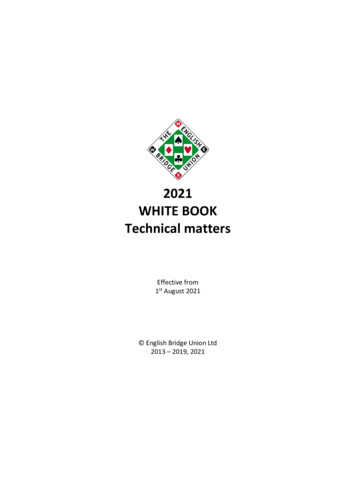
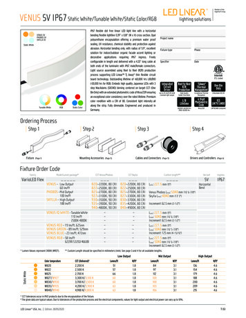
2An Introduction to OpenRANIntroductionAs global cellular data usage continues to increase, the way we build telecommunications systemsmust change to keep up. While the 5G standard meets demands for more cellular throughput andaims to address new use cases, many applications identified in the 5G charter may not happenwithout network evolution. Specifically, the ultrareliable low-latency (URLLC) use case demandsthat networks meet a latency spec—impossible without network changes. Future networks needto be more flexible and take advantage of new technologies such as artificial intelligence. Networkoperators want to move toward software-defined networking to customize and manage theirdeployed networks. Mobile network operators also need equipment interoperability, or the abilityto choose different network equipment components regardless of vendor. On the whole, thereis massive room for improvement to both radio access network (RAN) and telecommunicationsystem hardware.In Release 15, the 3GPP identifies three distinct gNodeB functions: Centralized Unit (CU), DistributedUnit (DU), and Radio Unit (RU). There are several ways to configure these three components, anddeciding which configuration is best depends on each individual network. Single-vendor gNodeBoptions may choose proprietary interfaces between these components. The O-RAN alliance, orO-RAN, focuses on achieving an unprecedented level of openness in the way 5G RANs are built.The group’s charter conveys how having open interfaces between the CU, DU, and RU translatesto building networks from white boxes instead of being vendor-locked for the whole system, andthat, by doing so, the RAN is more flexible, and network operators have more options. Also, thisapproach encourages more innovation from smaller companies that have not traditionally providednetwork hardware. More innovation and more options could mean potentially lower costs to deploynew networks. O-RAN also hopes to integrate deep learning techniques into every RAN architecture,making communications systems more intelligent. O-RAN’s reference architecture, shown in Figure 1,illustrates how to build an O-RAN-compliant RAN.ni.com/5g-test-ue
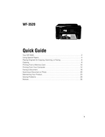
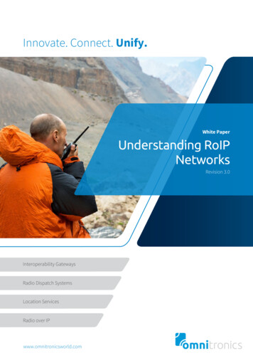
3An Introduction to OpenRANFigure 1. O-RAN Alliance Reference Architecture (Source: O-RAN White Paper)How to Split the RANO-RAN’s proposed concepts and architectures use a split-RAN concept. There are eight knownways to functionally split the RAN, and each one proposes splitting the processing so that differentparts of the protocol stack process on different hardware. Figure 2 summarizes the eight wPHYRFDownlinkDataRRCOption 1Option 2PDCPOption 3HighRLCOption 4LowRLCOption 5HighMACOption 6LowMACOption 7HighPHYOption 8LowPHYRFUplinkDataFigure 2. RAN Split Options (Source: NGNM 2018)ni.com/5g-test-ue
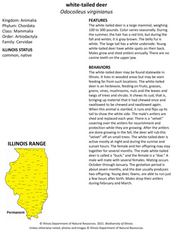
4An Introduction to OpenRANO-RAN proposes using option 7-2 which, as shown in Figure 2, splits the physical layer (PHY) intoa high-PHY and a low-PHY. For option 7-2, the uplink (UL) , CP removal, fast Fourier transform(FFT), digital beamforming (if applicable), and prefiltering (for PRACH (Physical Random AccessChannel) only) functions all occur in the RU. The rest of the PHY is processed in the DU. For thedownlink (DL), the inverse FFT (iFFT), CP addition, precoding functions, and digital beamforming(if applicable) occur in the RU, and the rest of the PHY processing happens in the DU.2G, 3G, and 4G use Common Public Radio Interface (CPRI), which is passed on an option 8 split.Moving to the 7-2 split reduces traffic between the DU and RU. O-RAN has specified a versionof the 7-2 split. Figure 3 below illustrates the 7-2 split, as well as how other parts of the protocolstack are split between the CU and the DU. The 7.2x split is the best balance between bringingthis technology to market quickly and deployment cost. It reduces confusion about split specificswhile making traffic reduction gains and improvements. Some 5G systems use evolved CPRI(eCPRI) as the DU-RU interface. eCPRI offers a vendor-specific split between the high and lowPHY. Thus, you can optimize for traffic or flexibility by supporting multiple splits, accommodatingdifferent deployment environments due to unique antenna physical environments. With thiscomes the freedom to cost-optimize for connections specific to different operators.E2CURRCSDAPPDCP-CPDCP-UF1E2DURLCMACL1C / MIMO / Mod / CodingHigh PHYORAN FH (CUSM-Plane)RUFFT/ iFFTLow PHYA/Ds, D/As, RFFigure 3. Protocol Layer Split Between CU, DU, and RU for Option 7-2For new 5G RAN architectures (called NR-RAN), the 3GPP has defined and standardized on anew interface, the F1 interface, for communication between the CU and the DU. When the CUand the DU are physically split, it is called a higher-layer split (HLS). While not defined by the3GPP, the lower-layer interface between the DU and the RU is called a lower-layer split (LLS).You can configure the CU and DU in relation to each other and in relation to RUs in several ways.Figure 4 diagrams various NR-RAN configurations. Note that the F1 interface is delay-tolerant,while the DU-to-RU interface needs to be low-latency. Given the challenges of creating low-latencyinterfaces, the rest of this paper details a central RAN with a lower-layer split use case.ni.com/5g-test-ue
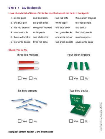
5An Introduction to OpenRANCentral RAN(LLS)Split RAN(HLS)Dual split RAN(HLS LLS)Remote CU-UP(HLS)Central CU-UP(HLS)Edge siteEdge siteEdge siteEdge siteEdge l siteF1uRURUCU-UPE1F1cE1CU-UPE1Cell siteAgg siteCell siteCell siteCell siteDUCU-UPCU-UPCU-UPCU-UPRURULocal appLocal appLocal appLocal appDUCU-UPCU-UPDUDURURURURUDUF1uF1uDelay tolerantLow latencyCell site RAN(monolithic)Cell siteRURURURUF1uFigure 4. 5G RAN Functional Unit Location Flexibility (Source: NGMN, 2018)The interface between the DU and RU also is known as the fronthaul (FH) interface. The FHinterface, one of the most demanding system interfaces, is very latency-sensitive. Where theDU and RU come from the same manufacturer, most systems use CPRI or eCPRI (5G only)as the FH interface. While CPRI originally was intended as an open interface, in practice, eachvendor implemented it in a slightly differently way to work with their own hardware, renderingmultivendor interoperability difficult or impossible. While not encouraging an open, white-boxhardware architecture, you can more easily achieve tight synchronization between the DU andRU. When the DU and RU are from one vendor, they are matched in terms of when to send andwhen to receive (the only variation being the distance between DU and RU).One of O-RAN’s two goals is to create more open ecosystems, which requires defining a newFH interface. One of the seven O-RAN working groups, working group 4 (WG4), is dedicated todefining this interface. Called the Open Fronthaul Interfaces Workgroup, its objective “is to delivertruly open fronthaul interfaces, in which multivendor DU-RRU interoperability can be realized.”Figure 5 shows how the proposed DU-to-RU interface exchanges information in different planes.While the seven different flows—plus additional management (M)-plane flows—may seemdaunting, at a higher level, there are only three data types (IQ data; timing and sync data; andcommand and control information) across four total planes (control, user, sync, and management).ni.com/5g-test-ue
6An Introduction to OpenRAN1a: DL IQ data in FFT frequency domain1b: UL IQ data in FFT frequency domain1c: PRACH IQO-DU2a: Scheduling Commands (DL&UL) & Beamforming CommandsO-RU2b: LAA LBT configuration parameters and requests2c: LAA LBT status and responsesS: Timing & synchronizationNote: M-Plane flows not represented hereFigure 5. Lower Layer Fronthaul Data Flows (Source: O-RAN)Compared to CPRI, there are significant differences in how the IQ data is transferred, packed, andunpacked in the FH interface, since CPRI is based on an option 8 split. The option 8 split splitsthe network at the RF, so the IQ samples have not undergone any PHY processing (FFT/iFFT). Asnetworks evolved in the later stages of 4G and early 5G, eCPRI sought to reduce traffic causedby the increase in antennas and sampling rate (multiple samples per antenna) used in massivemultiple-input and multiple-output (MIMO). System traffic overwhelmed the physical connection,and connections that can accommodate the traffic are expensive to implement. To reduce trafficacross this interface, eCPRI moves certain parts of the PHY into the RU and adds compressionalgorithms. However, which pieces of the PHY are moved into the RU does not follow anyspecific split and differs from vendor to vendor. This could be a competitive advantage to somevendors, and a way to potentially reduce the link cost for operators. Since part of the lower-levelPHY functions are in the RU, the DU needs to inform the RU how to perform these functions.This creates a very different command-and-control interface between eCPRI and O-RAN’s FHinterface as well. But having vendor-specific splits perpetuates a service-provider vendor lock.O-RAN’s open FH interface aims to standardize on which pieces of the PHY are moved into theRU by using the 7-2x split so that you can integrate hardware from different vendors.Interoperability Testing (IOT)As WG4 works to finalize an FH interface, they must consider how to test it. For systems containinga DU and RU from different hardware vendors, system integrators and vendors need the abilityto validate that the DU and RU interface properly. This type of testing is commonly referred to asinteroperability testing. O-RAN is investigating how to test an O-RAN-compliant system. Figure 6 isan O-RAN diagram showing what a test setup might look like for testing an O-RAN-DU (O-DU) andO-RAN-RU (O-RU) with an O-RAN-CU (O-CU) and a UE, which could be emulated or commercial.There is a test point to look at the interface between the CU and DU, and one to look at the RU RFinput/output, but the DU and RU are combined as the device under test (DUT). This leaves the FHinterface between the DU and RU untested when using active stimulus and only considered forpassive monitoring. O-RAN currently is looking at how to test the FH interface.ni.com/5g-test-ue
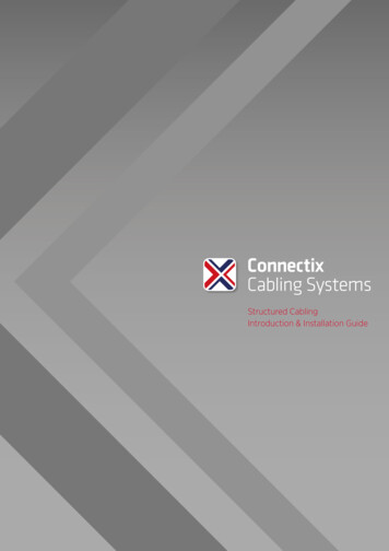
7An Introduction to OpenRANAPP Test Server /Core / MeNB / O-CUAPP Test Server /Core / MeNB / O-CUDUT-1(O-DU)O-DUDUT1Cabled(Ethernet)FH ProtocolAnalyzerDUT-1(O-RU)O-RUDUT2DUTDUTRF(Cabled or OTA)RF/BeamAnalyzerTest Results &KPIs LoggingUEs(emulator)Test toolDevices(emulator)DUTFigure 6. O-RAN Test Setup, Active (Left) and Passive (Right) (Source: O-RAN)There are two kinds of active testing to consider for the FH interface: Protocol testing andparametric testing. O-RAN has shown that protocol testing is necessary for test-case validationand troubleshooting. Having test tools to validate designs during development is key tointerfacing successfully with other O-RAN-compliant devices. After the design is finalized andDUs and RUs enter the validation and production stages, parametric tests make sure that eachunit performs as expected.For an RU tester, the E1 interface between the CU and DU does not need to be tested. An RUtester must emulate both CU and DU functionality and be able to monitor the FH interface.Depending on required testing level, adding a test UE or UE emulator to the system can create afull end-to-end (E2E) tester. NI provides 5G NR IP based on its software defined radio (SDR) andFPGA hardware. An example E2E tester is shown below in Figure 7.PXIe-1085 Gen37902PXIe-8880Intel Xeon 8-core790279027902457915PXIe-1085 Gen37902PXIe-8880Intel Xeon 8-core7902790279027915Cabledor OTAFH Interface1123456782367899USRP-2944CU DU (based on NI gNB)USRP-2944RU (DUT)NI Test UEFigure 7. E2E DU-RU Tester Exampleni.com/5g-test-ue
An Introduction to OpenRAN8ConclusionO-RAN maintains three goals:nCreating a smarter RAN that takes advantage of being able to virtualize pieces of the networkfor maximum efficiency gainsnSupporting white-box hardware for multivendor network solutionsnCreating standardized interfaces between network componentsBy delivering on these key initiatives, O-RAN aims to evolve networks to be more future-proof andincorporate new 5G-promised features and use cases, such as URLLC. The FH interface, in particular,is challenging because of the low latency required for DU-to-RU communications. O-RAN’s WG4 ismaking progress to define this interface, and companies are beginning to build O-RAN-compliant RUsto connect to other O-RAN-compliant hardware. Being able to validate and test the DU-RU interfaceis important in both the design and validation stages, as well as in production test, as this newtechnology comes to market. By offering IOT testing hardware and software, NI can help acceleratebringing new O-RAN-compliant RUs to market. Whether O-RAN is widely adopted and used in 5Gnetworks remains unclear; however, as of now, the alliance actively is working towards defining newinterfaces and seeking ways to use multivendor hardware solutions to build new networks for thesake of improving and advancing the way that networks are built. 2020 National Instruments. All rights reserved. LabVIEW, National Instruments, NI, and ni.com are trademarks of National Instruments. Other product and company names listed are trademarksor trade names of their respective companies. 35779ni.com/5g-test-ue
Mobile network operators also need equipment interoperability, or the ability to choose different network equipment components regardless of vendor. On the whole, there . Local app F1u F1c E1 Cell site Edge site RU RU CU-UP CU-UP DU Cell site RAN (monolithic) Local app Cell site RU RU CU-UP DU CU-UP Central RAN (LLS) Cell site Edge site RU CU .