Transcription
Pipelines 2018122The New Interactive AWWA M11 Flange Bolt Torque CalculatorIts Background, Relevance, and UseA Technical Guide toJohn H. Bambei Jr., P.E., M.ASCE1; Elizabeth S. Ralph, P.E.2; David Lay3;and Brent D. Keil, P.E., M.ASCE4Downloaded from ascelibrary.org by Richard Mielke on 07/19/18. Copyright ASCE. For personal use only; all rights reserved.1Chair of AWWA Steel Pipe Committee; Owner, Bambei Engineering Services, LLC, 6781West Woods Circle, Arvada, CO 80007. E-mail: john.bambei@gmail.com2AWWA Staff Liaison to the Steel Pipe Committee; Staff Engineer, AWWA, 6666 West QuincyAve., Denver, CO 80219. E-mail: lralph@awwa.org3Member of SWPMTAC Pipe Group; Director of Training (Ret.), Hytorc, 9834 North 6180West, Highland, UT 84003. E-mail: davidlay@hytorc.com4Chair of SWPMTAC Pipe Group; Chief Engineer, Northwest Pipe Company, 5721 SEColumbia Way #200, Vancouver, WA 98661. E-mail: bkeil@nwpipe.comABSTRACTThe sequence of tightening bolts and controlling torque are very important to the assembly offlanged pipe joint connections. Among other factors, proper-flanged joint closure depends onapplying the correct amount of gasket load and achieving uniform load around the joint. Sincethe load applied to the joint by the bolts is difficult to measure directly, torque is used as aconvenient way to approximate the desired load. This paper will review torque calculations asthey apply to ANSI/AWWA C207 flanges and the new AWWA web-based interactive tool,including examples for torque calculations as described in the recently published, AWWAManual M11, Steel Pipe A Guide for Design and Installation, 5th Edition.BACKGROUNDThe success of flanged joints depends on applying the correct amount of gasket load andachieving uniform load around the joint. ANSI/AWWA C207 (2018) states requirements forflange facing, gasket material, and bolting material. Flanges are to be flat faced, withoutprojection or raised face with a serrated concentric or spiral finish with a resultant finish of 125to 500-µin. roughness. Gasket material may be either rubber, compressed fiber or PTFE(polytetrafluoroethylene). Bolting material shall be ASTM A193 grade B7 with ASTM A194grade 2H heavy hex nuts for bolts larger than 1 in. and ASTM A 563 heavy hex nuts for bolts 1in. and smaller.GASKET LOADAWWA M11 (2017a) states that gaskets seal joints as they are compressed to fillimperfections and spaces in the flange faces. Insufficient compression can result in imperfectionsand spaces not being filled and can also result in insufficient resistance to hydrostatic pressure.Excessive compression can result in pinching or crushing of the gasket and consequentlypossible leakage. Desirable gasket load is generated by tightening the bolts in a controlled anduniform manner, usually to a given percent of their yield. By convention and design, mostbolting of gasketed flanges is carried out to achieve a stress of approximately 50 percent of boltmaterial yield strength. The sum of all the bolt loads in the joint divided by the contact area ofthe gasket with the flanges equals the gasket stress. ASCE
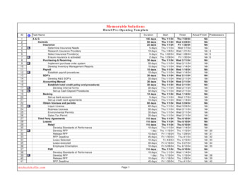
Pipelines 2018123Downloaded from ascelibrary.org by Richard Mielke on 07/19/18. Copyright ASCE. For personal use only; all rights reserved.BOLT LOADAWWA M11 (2017a) states that it is the bolt load that compresses the gasket and seals thejoint. However, it is not just how tight the bolts are, but also how consistently they are loadedthat ensures a proper seal. The intent is not just to achieve a sufficient load but also to minimizevariations among the bolts. A complication to achieving uniform tightness is that bolts act likeinteractive springs in the joint. Tightening any one bolt will change the effective load of thenearby bolts. No matter how accurately torque or tension is initially applied to any single bolt, asubsequent retightening of all the bolts must be done to even out the load. A further complicationis that although bolts react quickly and completely as loads shift during tightening, soft gasketmaterials do not exhibit similar resilience. Care must be taken to not overcompress the gasketbecause it may not spring back to fill the void if the load under any one bolt is reduced. That isthe reason for gradually increasing the pressure in stages to the final load. In order to even outthese loads, bolts are tightened in a specific sequence using gradually increasing passes or stepsto achieve the final tightness.Fig. 1 Bolt Tightening Pattern From ANSI/AWWA 604 (2017b)ANSI/AWWA C604 (2017b) provides guidance on various tightening patterns that can beused. Fig. 1 is an example of one of these patterns. Whatever pattern is chosen, it shouldaccomplish several interrelated goals toApply sufficient bolt stress to maintain a leak-free connectionAchieve uniform bolt stress and therefore uniform gasket stress around the flange ASCE
Downloaded from ascelibrary.org by Richard Mielke on 07/19/18. Copyright ASCE. For personal use only; all rights reserved.Pipelines 2018124Maintain parallel closure of the flanges during tighteningMinimize excessive loading/unloading of the gasket during tighteningAvoid overcompression or crushing of the gasketReduce tool movements to improve efficiencyBe simple to implement for the assemblersSince the load applied to the joint by the bolts is difficult to measure directly, torque is usedas a convenient way to approximate the desired load. Load is achieved by a controlled turningforce (torque) applied to the bolt head or nut. Torque is the product of a force times the distanceover which it is applied. Torque is developed by the turning of threaded nuts and bolts thatrequire surfaces to slide past one another. To accurately convert torque into load, the friction thatexists between the sliding surfaces must be known. Friction is reduced by the application of alubricant. It may take three times the torque to achieve the same bolt load with a dry fastener aswith one that has been lubricated.Nut-and-bolt assemblies have two sliding surfaces: (1) the mating threads and (2) the face ofthe nut where it contacts the flange. Therefore, the amount of force necessary to tighten anut/bolt to any given load value depends on the friction between the two surfaces.The relationship between torque and load in this context may be expressed by the followingformula cited in ASME PCC-1, appendix J (2013a):TF 0.16 p0.58 t d 2De2nTorque toTorque toTorque toStretchOvercomeOvercomethe Bolt Thread Friction Face FrictionWhere:T total tightening torque, ft-lbF bolt preload, lbµt coefficient of friction for the threadsn number of threads per in.d1 thread major diameter, in.d2 basic pitch diameter of the thread, in (for inch threads d2 d1 0.6495/n)p pitch of the thread; normally threads/ inch, i.e., p 1/nn coefficient of friction for the nut face or bolt headDe effective bearing diameter of the nut, in. (do di)/2Do outer bearing diameter of the nut, in.Di inner bearing diameter of the nut face, in.Notice in the above formula that the applied torque has to overcome three resistant forces:bolt stretch, thread friction, and face friction.To simplify this calculation, a formula that combines these three resisting forces into a singlevariable, K,formula cited in ASME PCC-1, appendix K (2013a).K Ds FT12Where:T torque the turning force required, ft-lb ASCE
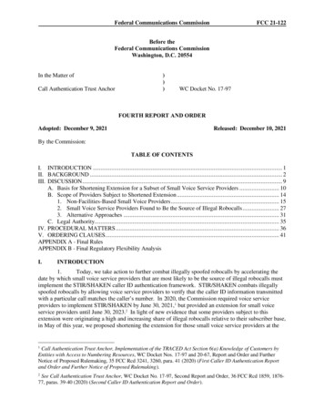
Pipelines 2018125Downloaded from ascelibrary.org by Richard Mielke on 07/19/18. Copyright ASCE. For personal use only; all rights reserved.K nut factor how hard it is to turn, expressed as a decimalDs nominal diameter of the stud, in.F load desired in the stud, lbK is an empirical value related to the total resistance, derived experimentally by applyingtightening torque to a bolt of a given nominal diameter in a scale device and observing theresultant load.Fig 2. AWWA Interactive Torque Calculation Tool (2017c)K is dependent on a number of factors such as temperature, quantity and application oflubricant to sliding surfaces, bolt diameter, thread pitch, fastener condition, and the applied load.Experience has shown the use of a nut factor to be for all intents and purposes as reliable andaccurate as the more complex torque formula, and it can be relied on to produce acceptableresults if consistently applied. Once determined, it is then applied generally to bolts of the samegrade and diameter to relate torque to load. At normal assembly temperatures with standardbolts, the derivation of Kfriction, µ (Bickford 1995). Coating or plating of bolts will also result in different frictionconditions and therefore different torque requirements that for uncoated fasteners. ASCE
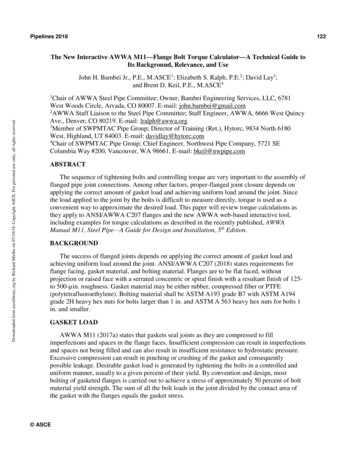
Pipelines 2018Downloaded from ascelibrary.org by Richard Mielke on 07/19/18. Copyright ASCE. For personal use only; all rights reserved.SUGGESTED VALUES FOR KAWWA M11 (2017a) states that tests conducted by Brown et al. (2006) showed that averageK values for a number of copper-, nickel-, molybdenum-, and graphite-based antiseize lubricantson standard ASTM A193 grade B7 studs were in a fairly consistent range from 0.16 to 0.18,regardless of assembly temperatures ranging from 23ºF to 105ºF. Consensus figures frommultiple sources place the K value for petroleum-based lubricants such as SAE 20 oil atapproximately 0.19 and for machine oil at approximately 0.21. Although dry alloy steel exhibit arather wide scatter of values, a K value of 0.30 has been successfully used.Testing by Cooper and Heartwell (2011) demonstrated that the presence of a throughhardened washer under the nut or bolt head has as great a positive effect on reducing overallfriction as the use of a lubricant. The conclusion being that a hardened washer should be usedunder all turning nuts both to reduce required torque and also to improve consistency of loadamong the bolts.TORQUE CALCULATIONS:The recently published, AWWA Manual M11, Steel Pipe-A Guide for Design andInstallation, 5th Edition (2017a) included a reference to an AWWA web-based interactive tool todo the torque calculations based on user input. The interactive tool can be found atwww.awwa.org/TorqueCalc. A screen shot view is shown in Fig. 2.The Torque Calculation Tool includes the following User Instructions:1. Select or enter Calculation Input values in each of the red highlighted fields2.3. If the finished flange face ID is known, enter it in the Finished Seating Face ID box.Otherwise leave the box blank (ID assumed for the calculation is shown in theCalculation Data)4.5. Input nut factor (based on lubricant friction factor)6. Once all red highlighted fields are filled out, select the CALCULATE button7.The user is able to select from ANSI/AWWA C207 (2013b) flange classes, gasket materials,and flange diameters. Based on the users input, the torque calculator generates a recommendedtorque range to select the appropriate torque value for the application. It also offers warning tothe user if they have a potential of either crushing the gasket with too high of a load or notgetting enough load to seat the gasket with their selected inputs.CONCLUSIONA successful flange installation requires the proper amount of load applied to the gasket. Theconventional way to achieve that load is by applying a measured torque to the flange bolts. Therecently published, AWWA Manual M11 includes a description of calculating torque values forbolting ANSI/AWWA C207 flanges including the addition of a web-based, interactive tool forcompleting the torque calculation. The interactive tool provides users a way to easily determinean appropriate torque for their AWWA C207 flange installation. ASCE126
Pipelines 2018Downloaded from ascelibrary.org by Richard Mielke on 07/19/18. Copyright ASCE. For personal use only; all rights reserved.REFERENCESASME (The American Society of Mechanical Engineers). (2013a) Guidelines for PressureBoundary Bolted Flange Joint Assembly, ASME PCC-1-2013, ASME, New York, NY.AWWA (American Water Works Association). (2018) Steel Pipe Flanges for WaterworksService, Sizes 4 In. Through 144 In. (100 mm Through 3,600 mm), ANSI/AWWA C207-13.AWWA, Denver, CO.AWWA (American Water Works Association). (2017a) Steel Pipe - A Guide for Design andInstallation, AWWA Manual of Water Supply Practices M11. Fifth Edition. AWWA, Denver,CO.AWWA (American Water Works Association). (2017b) Installation of Buried Steel Water Pipe4 In. (100mm) and Larger, ANSI/AWWA C604-17. Denver, CO.AWWA (American Water Works Calcs. AWWA, Denver, CO.Bickford, J. H. (1995). An Introduction to the Design and Behavior of Bolted Joints. Boca Raton,FL. CRC Press.Brown, W., L. Marchand, and T. LaFrance (2006). Bolt Anti-Seize Performance in a ProcessPlant Environment, New York, NY. ASME Pressure Vessel Research Council, PVP2006ICPVT11-93072.Cooper, W., and T. Heartwell (2011). Variables Affecting Nut Factors for Field AssembledJoints. New York, NY. ASME Pressure Vessels and Piping Conference, PVP2011-57197. ASCE127
AWWA M11 (2017a) states that tests conducted by Brown et al. (2006) showed that average K values for a number of copper-, nickel-, molybdenum-, and graphite-based antiseize lubricants on standard ASTM A193 grade B7 studs were in a fairly consistent range from 0.16 to 0.18, regardless of assembly temperatures ranging from 23ºF to 105ºF. Consensus figures from multiple sources place the K .