Transcription
Quantifying and Optimizing Data AccessParallelism on ManycoresJihyun RyooOrhan KislalXulong TangMahmut T. KandemirPenn State Universityjihyun@cse.psu.eduPenn State Universitykislal.orhan@gmail.comPenn State Universityxzt102@cse.psu.eduPenn State Universitykandemir@cse.psu.eduAbstract—Data access parallelism (DAP) indicates how wellavailable hardware resources are utilized by data accesses. Thispaper investigates four complementary components of data accessparallelism in detail: cache-level parallelism (CLP), bank-levelparallelism (BLP), network-level parallelism (NLP), and memorycontroller-level parallelism (MLP). Specifically, we first quantifythese four components for a set of 20 multi-threaded benchmarkprograms, and show that, when executed on a state-of-the-artmanycore platform, their original values are quite low comparedto the maximum possible values they could take. We next performa limit study, which indicates that significant performance improvements are possible if the values of these four components ofDAP could be maximized. Building upon our observations fromthis limit study, we then present two practical computation andnetwork access scheduling schemes. Both these schemes make useof profile data, but, while the compiler-based strategy uses fixedpriorities of CLP, BLP, NLP, and MLP, the machine learningbased one employs a predictive machine learning model. Our experiments indicate 30.8% and 36.9% performance improvementswith the compiler-based and learning-based schemes, respectively.Our results also show that the proposed schemes consistentlyachieve significant improvements under different values of themajor experimental parameters.I. I NTRODUCTIONIn today’s manycores with large number of cores, networkon-chip (NoC), multiple memory controllers (MCs) and a largenumber of memory banks, maximizing data access parallelism(i.e., how well hardware resources are used by data accesses)can be as important as maximizing computation parallelism(i.e., how well computations are parallelized). One optionalong this direction is to simply define data access parallelismas “memory parallelism”, the number of concurrent memoryoperations, and try to maximize that. For example, an earlycompiler work [52] on memory parallelism tuned iterationspace tiling to cluster memory accesses. Works along similardirections include [56], [5], [15], [62], [59], [20], [36], [35].While such efforts can be successful in certain applicationsand single-core architectures, given a large variety of emergingmanycore systems, an approach that exposes architecturaldetails to software can be a more promising option. In fact,instead of working with a high-level concept such as memoryparallelism, one may want to dig further and identify itsdifferent “components” to better understand its behavior andreshape it for performance benefits, which is the underlyingvision of this work.In an NoC-based manycore with multiple MCs and memorybanks, data access parallelism (DAP) can be divided into fourcomponents: cache-level parallelism (CLP), bank-level parallelism (BLP), network-level parallelism (NLP), and memorycontroller-level parallelism (MLP). CLP refers to the numberof L2 banks1 that are being accessed at a time when an L2bank is being accessed. Similarly, BLP captures the number ofmemory banks being accessed when a bank is being accessed.Clearly, higher values for CLP and BLP indicate higher levelsof cache-level and bank-level parallelism, respectively. NLPon the other hand indicates the number of NoC links beingexercised when at least one of the NoC links is active. Ahigher NLP value means that the workload utilizes a largerfraction of NoC. Finally, MLP captures the number of MCsthat are being used when one memory controller is active.Similar to the CLP and BLP cases, one would prefer highMLP and NLP values from a resource utilization perspective.Note that CLP, BLP, NLP and MLP capture different aspectsof DAP, and optimizing for only one of them does not necessarily lead to good results for the other three. For example, anexecution can utilize a large number of LLCs (high CLP), butif all cache misses go to a small set of memory banks, its BLPwould be quite low. While there exist prior studies that focuson each of these four components of DAP in isolation (mostof the existing studies are hardware based [11], [16], [41],[50], [54], [55], [30], [63], with only a few software-basedstudies [19], [43]), one can potentially achieve the maximumperformance by simultaneously exercising all of them. Withthis motivation, this paper makes the following contributions: It quantifies CLP, BLP, NLP and MLP for a set of 20multi-threaded applications, and shows that their originalvalues are quite low compared to the maximum possiblevalues. In other words, these multi-threaded applicationsdo not take advantage of DAP in their original forms.It performs a “limit study”, where it measures the potential of maximizing CLP, BLP, NLP and MLP in isolationas well as optimizing them together. The results indicatethat, when an entire application is considered, CLP andBLP play a bigger role, compared to NLP and MLP, inshaping the overall performance, and optimizing all fourcomponents can bring 40.9% performance improvementon average. However, the results also show that, for1 We assume an S-NUCA [32] based management of shared L2 as ourlast-level cache (LLC).
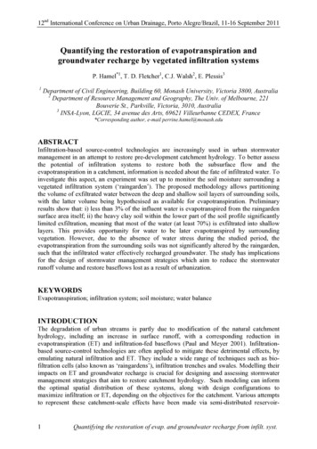
individual loop nests in an application, CLP, BLP, NLPor MLP may be the dominant component. It presents two practical computation and network accessscheduling schemes that target CLP, BLP, NLP and MLP.Both these schemes make use of ”profile data”, but,while our compiler strategy uses fixed priorities of CLP,BLP, NLP and MLP, our machine learning (ML) basedapproach employs a predictive learning model. It presents results using these two schemes. The resultsindicate that the fixed priority based scheme improves,under the default values of our system parameters, CLP,BLP, NLP and MLP by 45.5%, 54.6%, 20.0% and 37.9%,respectively, on an average. These improvements in DAPcollectively contribute to a 30.8% performance improvement, when averaged over all 20 programs. Further, themachine learning based scheme improves CLP, BLP,NLP, MLP and execution time by 55.4%, 75.3%, 36.3%,50.9% and 36.9%, respectively.The remainder of this paper is structured as follows. Section II introduces the target manycore architecture our studyfocuses on. Section III explains the computation parallelizationstrategy assumed by our work. The different components ofdata access parallelism are elaborated in Section IV. SectionsV and VI present the evaluation platform/workloads andexperimental results with the original applications. Section VIIdiscusses our results from an ideal (but not implementable)data access parallelism strategy, and Section VIII presents andevaluates two practical data access parallelism optimizationschemes: one is purely compiler based and one that employsmachine learning. The related work is discussed in SectionIX, and finally, the paper is concluded in Section X with asummary of our major findings and a brief discussion of theplanned future work.MCMCL1CoreL1L2 BankL2RouterMCMCFig. 1: Representation of an 8 8 NoC based manycore withS-NUCA and a sample memory access flow.address/data buses (referred to as channel). Each DIMM ismade up of multiple ranks; each rank consists of multiplebanks; and, all the banks in a rank share the same timingcircuitry. Each bank has a row-buffer, where the memory rowis loaded before the data corresponding to the request is sentback over the channel.As explained by Kim et al. [32], S-NUCA employs staticmapping for data. Typically, certain bits of the physical address are used for assigning data to L2 banks and memorybanks. There are multiple benefits this cache organizationprovides. Not enforcing uniformity means that the effectivecache capacity will be significantly larger than a uniform cachestructure. Since the cache banks are connected to each other,a miss on a local L1 might be mitigated by reading the datafrom another bank (remote L2), instead of requesting it fromthe memory controller. S-NUCA reduces the strain on thememory controllers and allows multiple data requests to workin parallel via the on-chip network. We provide the followingexample to discuss different scenarios that might occur witha typical S-NUCA system. Figure 1 shows an example ofmemory access flow in our architecture. When an L1 missoccurs, the request is forwarded to the node that accommodatesthe L2 bank that holds the requested data ( 1 ). If the requesteddata block is found in this home L2 bank of the data, it isread and sent back to the L1 cache in the requesting node ( 5 ).Otherwise, an L2 miss is said to occur, and a request is sent tothe MC that controls that channel to which the bank that holdsthe requested data is connected ( 2 ). This target MC schedulesthe request and, after reading it from the off-chip memory ( 3 ),sends the data back to the L2 home bank ( 4 ), and then tothe L1 cache ( 5 ). It is important to emphasize that, there arebasically two time-consuming activities involved in a memoryaccess: (i) time spent on traveling the NoC (which is a functionof both the number of links between the source and destinationas well as the degree of contention on the network) and (ii)time spent on accessing the off-chip memory bank. Clearly,maximizing DAP can reduce and/or hide the latencies of boththese activities. Specifically, maximizing CLP and BLP allowsmore caches and banks to serve a given set of requests, andsimilarly, high NLP and MLP values mean that the observednetwork and memory queuing latencies will be reduced.In this architecture, ”address mapping” defines how theII. TARGET M ANYCORE A RCHITECTUREFigure 1 shows the layout for an 8 8 network-on-chip(NoC) based manycore with static non-uniform cache architecture (S-NUCA). Each square represents a node that housesa core, a private L1 cache, a unified L2 bank (our last-levelcache, LLC), and a router. All L2 banks in the system are”shared” and collectively constitute our LLC. The rectangles(marked with MC) are used to show memory controllers(MCs). These MCs control/schedule the off-chip memory accesses (LLC misses). The arrows represent how the routers areconnected to each other and to the MCs. Even though variousdynamic message routing solutions exist in the literature, inthis work, we focus on an NoC with static routing (morespecifically, XY-routing, in which the message is routed firstin X or horizontal direction to the correct column, and thenin Y or vertical direction to the receiver node/core), since dynamic routing introduces significant performance and energyoverheads during execution.2 Each MC manages a DRAMmodule, also referred to as DIMM, by issuing commands over2 Note that, our NLP optimization changes the underlying routing policy fordata accesses. However, it is still a static routing and uses exactly the samenumber of network links as the XY-routing.2
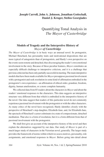
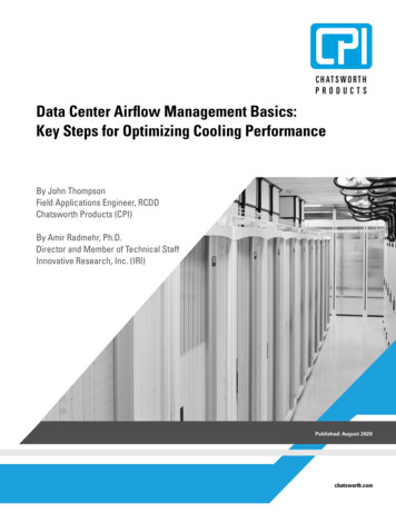
physical address space is distributed across multiple sharedcomponents (e.g., L2 banks, memory channels, banks) in asystem. Note that each component can have its own mappingstrategy. Depending on the mapping scheme employed, arequest (physical address) can result in an access to differentcomponents. There are various address mapping strategies,and the two widely-used are (i) cache line-level mapping, and(ii) page-level mapping. In the first one, the granularity ofdistribution is a cache line size, whereas in the second one, itis page size. In most of the experiments reported in this paper,we use a cache line-level distribution of physical addressesacross L2 banks, MCs and memory banks.OriginalLoopNestfor(i 0; i n; i ){for(j 1; j m; j ){A(i,j) B(i,j) A(i,j-1)}}TiledLoopNestfor(ii 0; ii n; ii ii 2)for(i ii; i min{n,ii 2}; i ){for(j 1; j m; j ){A(i,j) B(i,j) A(i,j-1)}}Fig. 2: An example loop nest, its tiled version (using rectangular tile shapes, in this case), and a pictorial representation ofthe tiles. In general, multiple tiles can be assigned to a core.Also, while in this case tiles are independent, in general onemay also have inter-tile dependences that need to be enforcedduring scheduling.III. C OMPUTATION PARALLELIZATIONThe primary focus of this paper is data access parallelism(DAP), and our proposed DAP maximization strategies (whichtarget all four components of DAP) can work with any computation parallelization strategy, which can be “compiler-based”or “user-specified”. In the specific computation parallelizationstrategy adopted in this work, given a loop nest, the compilerfirst extracts data and control dependencies and then tiles theloop nest.3 The specific tiling strategy used is based on [29].Note that this strategy is quite flexible and can choose nonrectangular tiles as well, if that strategy improves performance.For each loop nest in each application in our experimentalsuite, once the ”tile shape” is decided using the approach in[29], we experimented with different ”tile sizes” and selectedthe best tile size, i.e., the one that minimizes the overallexecution time.4Following iteration space tiling, the loop nest is parallelized.Note that, each “tile” represents a chunk of computations(iterations) assigned to a core for execution. The primarygoal in this parallelization is to maximize the number oftiles that can be executed by different cores in parallel.Consequently, the tiles are assigned to cores such that intercore tile dependencies are minimized as much as possible. Itis also important to emphasize that, in general, the numberof tiles is much larger than the number of cores, and as willbe discussed later, this gives the compiler some “flexibility”in scheduling. Figure 2 shows a loop nest, its tiled version,and the assignment of tiles to cores. In the rest of this paper,Tc,j indicates the jth tile assigned to core c.5 The next stepfollowing the tile-to-core assignment is to schedule the tilesassigned to cores. We do this in a DAP-oriented fashion, aswill be explained in the rest of this paper. A unique aspect ofMCMCMCMCMCMCMCMC(a)(b)Fig. 3: (a) Original case with a CLP of 1. (b) Optimized casewith a CLP of 4.our scheduling is that the tiles assigned to a core are scheduledby considering the scheduling of the tiles assigned to othercores as well.Note that, a program can exhibit high degrees of parallelismand processor utilization; however, if it does not have highvalues for different DAP components, its data request will experience significant delays on caches/MCs/network, eventuallydegrading the overall performance.IV. C OMPONENTS OF DAPBelow, we discuss in detail the four components/metrics ofDAP, namely, CLP, BLP, MLP and NLP.A. CLPAs stated earlier, physical addresses are distributed acrossthe available LLC banks. While one can define CLP in variousways, the definition adopted in this work is based on cacheaccess concurrency. More specifically, we define CLP as thenumber of LLC banks serving an L1 miss in an epoch of xcycles (where x can be calculated based on processor’s ROBsize). Clearly, a higher CLP value means better concurrentutilization of the LLC banks in the manycore system. While anapplication-conscious distribution of addresses to LLC bankscan also improve CLP, in this work, we try to improve CLP viacomputation (tile) scheduling. In other words, our strategy isto schedule tiles in different cores such that CLP is maximized.3 Iteration space tiling [65], is a well-known loop restructuring techniquethat is typically employed to exploit data reuse at the cache level or coarsegrain computation parallelism. In this work, we focus on the latter goal. Intiling, a given iteration space is divided into chunks (where each chunk holdsa set of loop iterations) and the iterations of each chunk are executed as abatch.4 We want to emphasize that this tiling strategy generates better results thanthe tiling strategy supported in compilers such as [28] and [1]. We believethis is due to the following two reasons: (i) the approach in [29] explores alarger set of tile shapes compared to [28] and [1], and (ii) our experimentationbased tile size selection strategy generates better tile sizes than [28] and [1].5 When no confusion occurs, we will also use Tc,j to indicate the tile thatcore c executes (at runtime) in step j.3
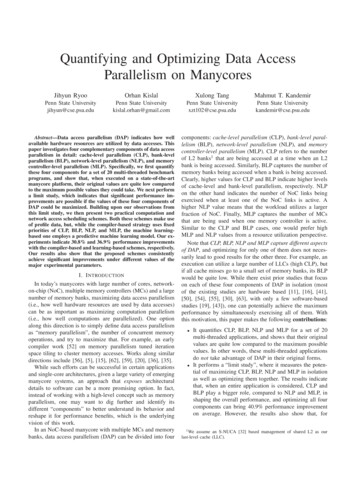
MCMCMCMCMC(a)(b)(c)Fig. 4: BLP vs MLP comparison. (a) Original case with a BLP of 2 and an MLP of 2. (b) BLP-optimized case. MLP is still2 but BLP is now 4. (c) MLP and BLP are optimized together (BLP 4 and MLP 4).MCMCMCMCMCMC(a)B. BLPMCWe define bank-level parallelism (BLP) as the number ofbanks serving the last-level cache misses in a small epoch(e.g., 128 or 256 cycles). Clearly, a high BLP value meansbetter (more balanced) utilization of available memory banksin the system, and can be expected to lead to higher applicationperformance (compared to a lower BLP value). While thereexist a number of prior works that targeted BLP, almostuniformly such works focused on BLP in isolation (Section Xdiscusses them), without looking at it in a larger context, alongwith other components of data access parallelism. Similar toour definition of cache vector (cv), we define a bank vectorbvc,j which is an s-bit vector, where s being the total numberof banks in the system. The kth bit of this vector is set to 1 ifTc,j accesses the kth bank in the system; otherwise, it is setto zero. Consequently, from a BLP viewpoint, one may wantto maximize the following expression at each scheduling stepj:bv1,j bv2,j · · · bvn,j .MC(b)Fig. 5: (a) Original case with an NLP of 7. (b) Optimized casewith an NLP of 12.Figure 3 illustrates, using an example, how CLP can beimproved. In the original case shown in (a), we have a CLPof 1, whereas in the optimized case shown in (b), the CLP is4. More specifically, in the original case, all four concurrentdata accesses (L1 misses) originating from the shaded nodesaccess the same L2 bank, whereas in the optimized case, thesame four requests go to different L2 banks.To achieve CLP-based scheduling, we represent each tileTc,j using a cache vector cvc,j a1 , a2 , · · · , am , whereeach bit ak of which indicates whether Tc,j accesses the kthLLC bank in the system. More specifically, bit ak of cvc,j isset to 1 if any iteration in Tc,j accesses the kth LLC bank;otherwise, it is set to 0. Our goal then is to maximize the valueof the following expression at each and every scheduling stepj:C. MLPMemory controller-level parallelism (MLP) is defined asthe number of MCs serving the last-level cache misses ina small epoch. Since one can have multiple outstandingrequests to the memory at a time which can potentially usedifferent channels, a low MLP value may cause some of thecontrollers to be overwhelmed (and can also congest the NoClinks around them), which can in turn degrade the overallapplication performance. From an optimization viewpoint, wewant to maximize the value of the following expression ateach scheduling step j:cv1,j cv2,j · · · cvn,j ,where denotes bitwise OR operation and n is the totalnumber of cores. In the ideal case, the result of this expression(which can be termed as the cumulative cache vector atstep j) is 1, 1, 1, · · · , 1, 1 , that is, it contains all 1s,indicating that all caches (LLC banks) in the system areaccessed at scheduling step j (when accesses from all coresare considered). While the CLP component of data accessparallelism is important, a high CLP does not guarantee highBLP, NLP or MLP. For example, an execution with a lot ofconcurrent L2 accesses to different L2 banks (high CLP) cangenerate L2 misses that mostly go to a small set of memorybanks (low BLP).mv1,j mv2,j · · · mvn,j ,where mvc,j , memory controller vector, is an r-bit vector (ris the number of memory controllers), where kth bit is set toone if Tc,j accesses the kth memory controller in the system;otherwise, it is set to zero.Note that improving one of BLP or MLP may not necessarily guarantee an improvement for the other. Let us considerthe three different cases depicted in Figure 4. (a) representsthe original case with a BLP of 2 and an MLP of 2, i.e., onlytwo memory controllers and two banks are accessed. In (b),4
TABLE I: System configuration.only BLP is optimized – BLP is now 4, whereas MLP is still2. Finally, in (c), both of the metrics are optimized – BLP is4 and MLP is 4.Manycore Size, FrequencyL1 CacheL2 CacheCoherence ProtocolRouter OverheadPage SizeOn-Chip Network FrequencyRouting StrategyDRAMD. NLPAs our last DAP metric, network-level parallelism (NLP)captures the number of NoC links that are simultaneouslyactive in a given short period of time. Clearly, a higher valueof NLP indicates a better use of NoC resources. We use nvc,jto denote the an l-bit vector, called network vector, where thekth bit (1 k l) is set to 1 if Tc,j accesses the kth NoC link;otherwise, it is set to 0. As a result, the NLP maximizationcan be expressed as the problem of maximizing the value ofthe following expression at each scheduling step j:Row-Buffer SizeAddress Distribution across LLCsAddress Distribution across banksEpoch Length64 (8 8), 1 GHz16 KB; 8-way; 32 bytes/line512 KB/core; 16-way; 64 bytes/lineMOESI3 cycles2 KB1 GHzXY-routingDDR3-1333; 250 request buffer entries;4 MCs 1 rank/channel; 16 banks/rank2 KB64 bytes64 bytes256 cyclesdefined in terms of its individual components. For example,everything else being equal, one may want to reduce thedistance (in terms of NoC links) between a requesting core andthe target L2 bank, so that average NoC latency per data accesscould be reduced. Where appropriate, we also report localitynumbers to show how aggressively optimizing for DAP canaffect the data access locality and overall application behavior.Now that we have defined the four main components ofDAP, we next evaluate them quantitatively for four differentscenarios: original applications, ideal case with optimum DAP,a pure compiler-based heuristic, and a machine learning (ML)based approach.nv1,j nv2,j · · · nvn,j ,In principle, NLP can be divided into two sub-components:NLP due to LLC hits and NLP due to LLC misses. However, ingeneral one may not want to balance LLC hits and misses (aswe want the latter to be as low as possible), and consequently,this division of NLP into two sub-components may not bevery important. That is, in practice, we do not care about thisdivision, as long as the overall NLP value is high. Figure 5illustrates the impact of NLP optimization. In (a), whichrepresents the original case, we have an NLP of 7, that is,only 7 links are used, whereas in (b) NLP is optimized to 12.V. E VALUATION P LATFORM AND W ORKLOADSE. DiscussionTo quantify DAP in multi-threaded applications as well asthe impact of optimizing it, we used a simulation-based study.We want to emphasize that currently it is not possible to collectdetailed statistics on different components of DAP (CLP, BLP,NLP and MLP) on an actual system, and this is why weconducted a simulation based study. Another reason is that wealso want to measure the impact of maximizing DAP via anideal scheme which cannot be implemented in real hardware.All the experiments reported in this paper are performedusing the GEM5 [7] simulation environment. GEM5 canmodel the system-level architecture as well as the processormicroarchitecture. Table I gives the main architectural parameters (along with their default values) that define the manycoresystem simulated in this work. The values of some of theseparameters are later modified to conduct a sensitivity study(Section VIII-C). In this work, each application is simulatedfor 1 billion instructions after the warm-up phase.We used 20 multi-threaded applications extracted from threebenchmark suites (mantevo [26], specomp [4] and splash-2[9]). The dataset sizes used in these programs range between751MB and 3.3GB. Their execution times, when runningon the configuration given in Table I, vary from 57.2sec to3.3min. To implement our compiler support, we used theLLVM compiler infrastructure [40]. In this work, we useLLVM as a source-to-source translator which takes a given(original) application program as input, and generates its DAPoptimized version as output. The optimized codes as well asthe original ones are then compiled using the node compilerwith the highest optimization flag (O3). The execution modelWhile computation (tile) scheduling can be used for improving CLP, BLP and MLP, we need a different mechanism toimprove NLP (though computation mapping has an impact onit as well). As stated earlier, by default, going from a sourcenode (e.g., core/L1 cache) to a destination node (e.g., L2bank) in our NoC is achieved using the XY-routing. However,between the same source-destination pair in our NoC, therecan be multiple routes, even if we restrict our search space tothe ones with the ”minimum number of links” (as in the XYrouting). More specifically, consider our 2D mesh-based NoCwhere a message, say m, is to be sent from a source node,(xs, ys), to a destination node, (xd, yd). If m xd xs and n yd ys , one can see that this message hasmunique shortest paths. Thus, one can select, for eachCm nmessage, a path such that the number of links used by allmessages is maximized, but none of the individual messagesuses more links than the XY-routing would use. In this work,we adopted the strategy used in [42], which is a deadlock-freeimplementation.6Also, while data access parallelism is important, it may notbe the only factor that affects performance. Clearly, for anapplication that has not been parallelized well, the role the dataaccess parallelism can play is limited. Further, ”data accesslocality” can also be very important for some applications.Like data access parallelism, data access locality can also be6 Note however that the goals of the two works are very different, as [42]tries to maximize link reuse to save NoC energy, while we are interested inmaximizing the number of NoC links used.5
21910equake6050403020100NLP20Fig. 8: MLP results over time for three representative applications in their original 120137154171188apsi10ProgressFig. 6: CLP results over time for three representative applications in their original LPCLPammp60ProgressFig. 7: BLP results over time for three representative applications in their original forms.Fig. 9: NLP results over time for three representative applications in their original forms.used in this work is similar to one that frequently appears inhigh-performance computing: each application is parallelizedacross all available cores in the system, and we run one(multithreaded) application at a time.less-than-expected CLP values. First, due to temporal localityof data accesses, only a subset of the available L2 cachesis actively used at any given execution period. Second, dueto the existence of an NoC, it takes some time for a dataaccess to reach its target L2 bank, during which the cacheremains idle, if there are no other request being served bythe same cache bank. Third, most of these applications havesome ”computation-intensive” periods as well, where there arenot many data accesses, which also contribute to low CLPnumbers.Figure 7 gives the BLP variations of three representativeapplications (apsi, barnes and applu) over time. As in thecase of the CLP values, these BLP values are not veryhigh (considering that the maximum possible BLP value is4 16 64), and one can see from the first bar for eachapplication in Figure 11 that, the average BLP values across20 applications is around 23.4. The reason for these low BLPvalues may change from one application to another. In mostof the applications with low BLP, the reason is the lack ofsufficient LLC misses to fill the available banks; and in theremaining ones, it is the locality of LLC misses, that is, theLLC misses (just like LLC accesses) also exhibit locality andtend to concentrate on a small number of memory banks ata given period of time. Again, adopting a page granularitydistribution of physical addresses across the banks (as opposedto the cache line granularity used in our default setting) led tosignificant reductions in the BLP values plotted in Figure 11(24% reduction on average).We next consider the MLP variations for three of ourapplications (phdMesh, art, and gafort) in Figure 8. Keepingin mind that the maximum possible value for MLP in ourdefault architecture is 4 (Table I), these values are quite low,giving an average of 2.1 (see the first bar for each applicationin Figure 12), due to the skewing of the last-level cache missestowards 1 or 2 of the memory controllers in a given executionwindow.Finally, the results for the three sample NLP traces presentedin Figure 9 (for applications equake, art, and swim), and theoverall NLP values shown as the first bar for each applicationVI. E VALUATION OF DATA ACCESS PARALLELISM OF THEO RIGINAL A PPLICATIONSNow we quantify CLP, BLP, MLP and NLP of the originalapplications.When we say “original applications” we meanno DAP-specific optimization is employed. However, eachapplicati
banks, data access parallelism (DAP) can be divided into four components: cache-level parallelism (CLP), bank-level paral-lelism (BLP), network-level parallelism (NLP), and memory controller-level parallelism (MLP). CLP refers to the number of L2 banks1 that are being accessed at a time when an L2 bank is being accessed.