Transcription
Available online at www.sciencedirect.comProcedia Engineering 10 (2011) 1059–1068ICM11Life extension of FPSO’s structural details using ultrasonicpeeningLuis Lopez Martinez*LETS Global , Postbus 50531; 3007 JA Rotterdam, Netherlands.AbstractFatigue life extension has been achieved by the application of ultrasonic peening to high stressed areas on pallet stoolto deck and longitudinal to frames weld details on FPSO installations. High stressed welds showed too short fatiguelives in as-welded condition. The aim with the ultrasonic peening treatment was to avoid any further weld repairsduring the remaining service life of these installations. Fatigue test results of treated relevant weld details have beenused to assess the potential life extension. The results showed four to six times fatigue life extension. The fatigue testwas designed to confirm that relaxation by external loads of the induced compressive stresses during treatment wouldnot diminish the benefit. The fatigue lives for the treated welds were extended up to twenty years which often is thetargeted service life for these installations. Quality Assurance and Quality Control were covered by UltrasonicPeening Procedure Specification, applied for every treated weld. It ensures that the treatment is exactly reproduced toachieve the expected life extension. 2011 Published by Elsevier Ltd. Open access under CC BY-NC-ND license.Selection and peer-review under responsibility of ICM111. IntroductionThe application of fatigue life improvement techniques is gaining popularity during the last years.Classification Societies have been focusing more and more on these techniques and the latest documentdealing with it [1] presents recommendations for weld toe profiling by machining and grinding, weld toegrinding, TIG-dressing and hammer peening.* Tel.: 31654304884; fax: 31102234618.E-mail address: luis.lopezmartinez@lets-global.com1877-7058 2011 Published by Elsevier Ltd. Open access under CC BY-NC-ND license.Selection and peer-review under responsibility of ICM11 doi:10.1016/j.proeng.2011.04.175
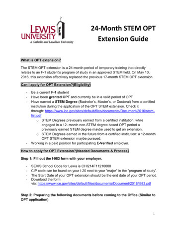
1060Luis Lopez Martinez / Procedia Engineering 10 (2011) 1059–1068Fatigue life improvement techniques can contribute to reduce maintenance cost by the avoidance ofrecurring weld repairs. Furthermore life extension techniques are the only remedy when higher stressesand/or fatigue cracks occur in a structure with many years remaining service life.The fatigue life assessment of the treated details in the as welded condition was based on spectralfatigue analysis carried out by Bureau Veritas. The assessment showed too short fatigue lives forstructural integrity relevant welds before treatment and the aim with the ultrasonic peening was to avoidany further weld repair during the remaining service life of the installations at these specific locations.1.1. Fatigue strength of welds and structural integrityAllowable design and service stresses and hence the structural integrity of offshore structures is nearlyalways governed by the fatigue strength of welded joints. The poor fatigue strength of welded joints canbe attributed to the conjoint effect of three factors: local stress concentration of stress due to the geometricdiscontinuity of the joint; the presence of sharp crack-like flaws like undercuts, slag intrusions, cold-laps,etc introduced by the welding process; and the presence of high tensile residual stresses in the weld metaland the surrounding heat affected zone, HAZ. In order to achieve fatigue life extension on a welded detailit is necessary to address these three factors.1.2. Ultrasonic Peening TreatmentThe three factors mention in 1.1. are modified by ultrasonic peening in a solely working operation.Hence the fatigue life extension by ultrasonic peening is achieved in part by the reduction of thegeometrical stress concentration at weld toe and in part by the redistribution of weld induced residualstresses, see Fig 1 and Fig 2. The redistribution of tensile residual stresses originated during and afterwelding procedure interacts with the compressive residual stresses which are induced into the HAZduring the ultrasonic peening treatment. The redistribution of residual stresses, including the introductionof compressive stresses, contributes towards fatigue life extension by locally lowering the mean stress.However, these induced compressive stresses could be relaxed during the remaining service life of thestructure.Fig 1 Weld toe grooveFig 2 UP Treatment
1061Luis Lopez Martinez / Procedia Engineering 10 (2011) 1059–1068The most apparent result of the ultrasonic peening treatment is the modification of the weld toeregion. This modification consist of the introduction of a groove at the weld toe which effectively cleansany existent cold laps, intrusions, weld spatter, etc, Fig 1. Simultaneously it clearly reduces the previousexistent sharp transition at the weld toe which means a substantial reduction of the local stressconcentration, Fig 2. The parameters showing the modification of the weld profile due to the ultrasonicpeening treatment are presented in Table 1. It is also important to mention the influence on fatiguestrength of the weld flank angle after the ultrasonic peening treatment has been applied.Table 1Geometrical weld parameters before and after application of the ultrasonic peening treatmenttWeld flank angleWeld toe radiusWeld groove depthWeld groove widthWeld surfaceBefore treatmentVariesn/an/an/aSpatter, start/stopAfter treatment45Σ2 mm0.5-0.8 mm4.0 mmSmooth shinyThe weld flank angle could play an important roll if not taken into account by the ultrasonic peeningprocedure [6]. This subject is extensively treated in ref. [6] but here we could name that an extreme weldflak angle could limit the enhancement achieved by the ultrasonic peening. Therefore the LETS Global ultrasonic peening procedure allows for the weld flank angle to be machined to a certain maximum valueto achieve the full benefit of the ultrasonic peening treatment.1.3. Ultrasonic peening procedureThe selection of weld connections for ultrasonic peening treatment is based on local FEA model andits result presented in 3. Thus, the procedure described here below is achievable and will be beneficialonly if the local FEA results are precise and its analysis is accurate. The full benefit of ultrasonic peeningtreatment is strictly dependent on this ground. The LETS Global ultrasonic peening procedure consist offive distinct steps which have been developed in accordance with our extensive experience withultrasonic peening treatment on offshore installations.1.3.1. NDT inspection previous to ultrasonic peening treatmentA selected weld joint for treatment on an operating structure have normally been in service for at leasthalf of its design life before we carry out the ultrasonic peening. As a result we need to ensure that if anyfatigue crack would be found, their size(s) would be such that the treatment will still restore its fatigue lifeand/or reset the clock to zero as a minimum value for that specific weld location. If the crack found showsto be too deep in relation to plate thickness the crack would need to be weld repair previous to theapplication of the ultrasonic peening treatment.1.3.1.1. Crack depth which can be treated with avoidance of weld repairFig 8 shows a comparison between the fatigue life improvements achieved by ultrasonic peening andhammer peening. Fatigue test results reported in literature [8], [9] demonstrated that cracks of 2.5 mm orless could be effectively treated by hammer peening and the fatigue life of these welds would be restored.Furthermore, the results in Fig 8 shows higher allowable stress ranges for the ultrasonic peening treatedwelds than for hammer peening. Hence, the strength factor for ultrasonic peening improved welds is 2.1and for hammer peening 1.6. Nevertheless, the absolute depth of the hammer peening treatment could be
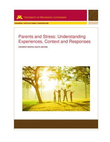
1062Luis Lopez Martinez / Procedia Engineering 10 (2011) 1059–1068deeper than ultrasonic peening since normally some pre-machining of the groove takes place. This wouldbe however compensated by the depth of the plastic deformed layer and the induced compressive stressesdown to a 1.5 mm achieved by the ultrasonic peening treatment. Consequently, a weld with a crack of 2.0to 2.5 mm deep, plate thickness 20 mm, treated by ultrasonic peening would be restored to its originalfatigue strength as a conservative estimate. It should be mention that the majority of the fatigue cracksdetected by us previous to the treatment are long cracks located along the weld toe and relatively shallow.1.3.2Preparation of weld toes previous to ultrasonic peeningThe weld toe and weld reinforcement must be cleaned previous to the treatment using sand blast orneedle gun. This is to remove all coating and other surface impurities and to ensure the peening workingtool have access to a clean metal surface on the weld and HAZ. After this cleaning operation is completedthe preparation of weld toe area can start with a pin tool of 3.0 mm diameter. This is to achieve thecomplete removal of all cold laps, lack of fusion defects, weld spatter, etc which are located at weld toe.This stage of the procedure is finished when the groove at weld toe shows a shiny and clean surface. Thesame course of action will apply for weld toes in between inter-pass weld passes. Also start/stop locationsshould be treated to remove any potential crack sites at these weld imperfections.1.3.3. Weld toe groove formationWeld toe groove formation is done with a 4 mm pin tool diameter to achieve a reduction of geometricalstress concentration. The final radius at weld toe transition to plate will be 2.0 mm and groove 0.5-0.8mm deep. Furthermore, the metal surface at the weld toe groove will be completely clean from anyimpurity and/or weld spatter. It is also important that the weld toe groove follows the contours of all weldtoes including eventual start /stop located on the weld. The same requirement will apply for inter-passweld toes. In addition the entire weld toe groove should have a constant radius of 2.0 mm and a constantdeep of 0.5-0.8 mm. Fig 3 shows all the contours at weld toes including those in the weld reinforcement.Fig 3 Weld contours treatmentFig 4 Treatment of entire weld surface1.3.4. Treatment of weld reinforcement or weld surfaceStructural welds are normally done as multi-pass welds. As a result it will exist besides the normalweld toe to plate additional weld toes adjacent to the first one but situated on the weld reinforcement. It isalso normal to encounter weld spatter on the weld reinforcement of a multi-pass weld. All these stressrisers plus “normal” cold laps could and will act as fatigue crack start sites and therefore it is ofparamount importance to remove all these sites when and if they are situated in high stressed areas.Therefore a standard part of our ultrasonic peening procedure, but only when required, is to treat the
1063Luis Lopez Martinez / Procedia Engineering 10 (2011) 1059–1068entire weld reinforcement with a multi-striker working head, Fig 4. The multi-striker peening toolcontributes also towards the fatigue life extension of the weld by redistributing tensile stresses inherent toevery welding procedure and/or by the introduction of compressive stresses.1.3.5. Quality Control & Quality Assurance of the ultrasonic peening treatmentThe application of LETS Global ultrasonic peening procedure can only be performed by certified andqualified operators [12] with the appropriate equipment. These operators have both the theoreticalunderstanding of the fatigue process and several years of continuous practice with the application of thetreatment on offshore structures. The starting point for our QA & QC is the qualification and experienceof the ultrasonic peening technicians who apply in-situ the treatment, carefully described in [12].Table 2Example of ultrasonic parameters for one pass weld on single pin, Ø 4 mmtFrequencyUltrasonicPowerPowerFast SweepingSweepingTrackingPWMPeriodPWMRatio19.7 kHz150040%0260-1510ms100The parameters presented in Table 1 and Table 2 are part of the ultrasonic peening procedure andensure that the improvement achieved in previous treated welds in laboratory, and used as reference toassess the degree of fatigue life extension, can be exactly reproduced on every structural member treatedon the installation.2. Experimental procedure and fatigue test resultsIn order to evaluate the degree on the fatigue life extension of ultrasonic peening treated weldsextensive fatigue testing has been carried out and it is regularly undergoing. A representative weldeddetail in reference to weld connection in the real structure has been selected for fatigue testing.2.3. IIW Recommendations for the specific weld detail.The denominations of the relevant fatigue tested welded details are Class F or Class F2 according tothe BS 5400 [11]. Currently this denomination has been widely replaced by the denomination proposedby the IIW Recommendations [2] in which both fatigue test details, Class F and Class F2, are classified asFAT 71 detail. FAT 71 refers then to fatigue strength of 71 MPa at 2.106 cycles. This value is called theSN Design Curve and it is calculated as the mean value minus two standard deviations for series ofpredetermined number of specimens. The IIW Recommendations for this weld detail are presented inTable 3 both in terms of mean value and as design values.Table 3FAT Values, Design Curve and Mean values according to IIW Recommendations for Class F2 and Class F weld detailsFAT designFAT – 50 %As-welded71 MPa102 MPaAs-welded Ultrasonic Peening112 MPa60 MPaM n TheThe fatigue test series for Class F specimens have been carried out on three point bending samples. This
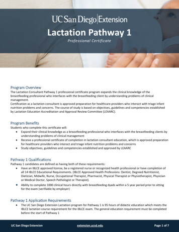
1064Luis Lopez Martinez / Procedia Engineering 10 (2011) 1059–1068specimen allows for the application of comppressive stresses direct to the ultrasonic peening treated weldwtoes, Fig 6.2.2. Class F DetailutionThe fatigue life improvement by ultrasonnic peening is normally achieved in part by the redistribuof weld induced residual stresses and in part by the change of the geometrical stress concentration at weldwtoe, see Fig.1. This redistribution of residuual stresses, including possible introduction of compresssiveresidual stresses would act positively towwards life extension but could also be relaxed during theremaining service life of the structure.Fig. 5. Ultrasonic peening treatmentFig. 6. Fatigue test specimenTherefore the weld details were preloadedd in compression bending 5 times up to 85% of yield strength(nominal stress) before fatigue testing, see Fiig 7. Since the ultrasonic peening treatment is responsiblee forcertain redistribution of residual stresses, asa previously explained, it is critical to document howw themechanical relaxation by compressive loadds of by the treatment induced residual stresses affectss thegeneral degree of improvement. The results are shown in Fig 8 [7].Fig 7 Pre-loading sequenceFig 8 Fatigue test results
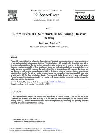
Luis Lopez Martinez / Procedia Engineering 10 (2011) 1059–10682.3. Class F2 DetailThe Class F2 test specimen is shown along the test results in Fig 9. The specimen has a non-loadcarrying full penetration weld attaching a longitudinal stiffener on both sides of the plate. One feature,which makes this fatigue test specimen particular, is the high degree of residual stresses concentrated atthe crack site, which is designed to be the weld toe at the stiffener.Fig 9 presents the fatigue test results as mean SN Curves for Class F2 weld detail where we can alsosee fatigue test results for UIT [5] along with the UP treated specimens. The fatigue test results for thesetwo treatments are almost identical which is also the general opinion in within the IIWRecommendations. The ultrasonic peening process is also known under the names “ultrasonic treatment”,“ultrasonic hammer peening”, “ultrasonic impact peening”, and “ultrasonic impact treatment”. Strictlyspeaking the treatment is performed in the same way and the results are almost identical.Fig 9 Fatigue test results for Class F2 weld details3. FEA Modeling of high stressed areasThe example presented hereby is a structural weld connection in an offshore structure [13]. FiniteElement Analysis and spectral fatigue analysis carried out by Bureau Veritas for a FPSO offshoreinstallation demonstrated critical fatigue lives for some welded connections on the ballast tanks. The levelof current stress ranges, taken as max principal stresses, were used to assess the potential life extensionthat could be achieved as well as to assess the areas and/or extension to be treated by ultrasonic peening.FEA Element size is normally chosen as a multiple or equal to relevant plate thickness and as resultthe extension of the high stressed areas which is also the area to be treated by ultrasonic peening can1065
1066Luis Lopez Martinez / Procedia Engineering 10 (2011) 1059–1068easily be assessed. However, some caution must be exercised due to certain approximations in within theFEA model and/or elements as well as variations in real plate thickness.3.1.Fatigue assessment and ultrasonic peening treatmentA side shell longitudinal stiffener connection to a transverse web frame was modelled and assessed interms of stresses and fatigue life with FEA. The model represented a typical weld connection showed inFig 10. The FEA model confirmed high stressed locations at the weld connection of longitudinal to webframe and to bulk head. As a result of these high stresses critical fatigue lives were found by the spectralfatigue analysis for these specific locations.Fig 10 FEA model courtesy of Bureau VeritasFig 11 UP treated connectionThe weld quality encountered in the real structure could differ from the weld quality described in asbuild drawings or assumed at the design stage of the installation. Therefore the ultrasonic peeningprocedure [12] needs to take into account these uncertainties when applied to achieve the desired fatiguelife extension. The weld in Fig 11 shows a high degree of irregularities on the weld reinforcement. Theultrasonic peening treatment has been applied to the entire weld surface. This ensures the removal of allthe potential fatigue crack sites of concern on the weld.4. ResultsFatigue life extension of weld connections on offshore installations in service is performed on existentwelds if not previous weld repair is needed. The quality of these welds do not always corresponds to theassumed quality and therefore the ultrasonic peening procedure [12] needs to take into consideration theas-built quality as a base-line to achieve a desired fatigue life extension. Therefore fatigue life extensionis a relative concept where the as-built weld quality plays an important role. We have determined awindow [6] where the variations of the as-built weld quality are taken into consideration.4.1. Fatigue test results of treated specimensIn the IIW Recommendations [2], the allowances for improved welds by peening methods are assessedin terms of SN Design Curves or FAT Classes. For steels with specified minimum yield stress below 350
Luis Lopez Martinez / Procedia Engineering 10 (2011) 1059–1068MPa, the improvement factor is 1.3 in stress corresponding to a factor 2.2 in fatigue life. It means anincrease from FAT 71 up to FAT 90 or 30% increase in stress for our specific weld detail. It is importantto note that the factor 2.2 in life comes from an assumed slope, m 3, for all SN Design Curves in [2].Hence, (1.3) m (1.3) 3 2.2 would be the improvement in life for peening methods according to SNDesign Curves. However, it is important to note that previous SN Design Curves showing fatigue testresults for ultrasonic peening improved welds demonstrated a less steep slope or m 3 and therefore itwould be reasonable to conclude the improvement in life could be greater than 2.2. If we assume a slopem 5.7 from [5] or m 5.5 from [14] for ultrasonic peening improved welds, the improvement in lifewould be from (1.3) m (1.3) 5.7 4.5 to (1.3) m (1.3) 5.5 4.3. For the sake of simplicity for slopem 5.5 and m 5.7 we assumed a 30% increase in stress.As an example we could assume a stress range of 250 MPa. The fatigue life for such stress range in theas-welded condition, FAT 71, is 50.000 cycles according to [2]. Furthermore assuming FAT 125 andstress range 250 MPa, would give us a fatigue life of 280.000 cycles. Hence an improvement of 5.6 timesin life is achieved for ultrasonic peening treated welds. Consequently, the suggestion of a general 4 timesfatigue life extension for ultrasonic peening improved welds seems to be in good agreement with currentFatigue Design Standards and also on the conservative side. This value could be applied also ifcompressive peak loads would occur during the remaining service life of the structure.4.2. Considerations about the application of the ultrasonic peening treatment in the offshore installationAs mention in 3 cautions must be exercised when selecting the area and extension to be treated byultrasonic peening. This is due to approximations in within the FEA model and/or its elements as well asto account for possible variations in real plate thickness from current production drawings to details in theinstallation. Standard commercial FEA codes express the principal stress in a specific element as a meanvalue of nodes or integration points. The implication of this algorithm is that a principal stress value ofone element is not necessarily the same as the maximum stress in within the same element.Furthermore, it is assumed that a certain level of accuracy, or minimized error level in the model isachieved. There is a number of ways to bring the error under certain acceptable level as n-convergence, pconvergence and/or energy norm error. The other aspect which needs to be taken into account is therelation between the element size in the local FEA model and the plate thickness in the structure. FEAelements showing certain level of stress will indicate the extension of the ultrasonic peening treatment.Therefore the relation between the FEA element size and the plate thickness is important otherwise thearea estimated to have high stresses and hence the area to be treated by ultrasonic peening will not be thecorrect one.5. ConclusionsFatigue life extension by ultrasonic peening has been achieved in high stressed areas on structuraldetails of offshore installations in service. The fatigue life assessment of these structural details was basedon FEA and spectral fatigue analysis. The assessment showed critical fatigue lives for the relevant weldsbefore treatment and the aim with the ultrasonic peening treatment was to avoid any further weld repairduring the remaining service life of the structure at these specific locations. The application of ultrasonicpeening for fatigue life extension had two main grounds:1067
1068Luis Lopez Martinez / Procedia Engineering 10 (2011) 1059–1068 For some of treated weld connections the ultrasonic peening treatment was the only solution leftto enhance the fatigue life since no structural modification option was possible. For other weld connections ultrasonic peening treatment was done before any of the analyzedfatigue problems occurred, since it was an easy relatively low cost solution rather than wait forcracks and implement weld repair an subsequent ultrasonic peening.On the basis of fatigue testing and relevant fatigue design standards the increase in fatigue capacity due toweld improvement by ultrasonic peening is estimate to be four times in life as a conservative estimate.The economical benefits due to reduced maintenance of structures as a result of the ultrasonic peeningtreatment include: Avoidance of long term plan for extensive repair workAvoidance of long and unscheduled operational disruptionsIncreased structural safety for the structure during remaining service lifeReferences[1] DNV-RV-C203 (2005) fatigue Design of Offshore Structures, August 2005.DNV.[2]Haagensen P.J. and Maddox S.J. (2004) “IIW Recommendations on Post Weld Improvement of Steel andAluminiumStructures”, IIW Doc. XIII-1815-00.[3] Lopez Martinez L. (1997) “Fatigue Behaviour of Welded High-Strength Steels”. Technical Report No. 97-30, The RoyalInstitute of Technology, Stockholm, Sweden.[4] Lopez Martinez L. and Blom A.F. (1997) “Influence of Spectrum Loading on the Fatigue Strength of Improved Weldments”,International Conference on Performance of Dinamically Loaded Welded Structures. Editors S. J. Madoxx and M. Prager; IIW 50thAnnual Assemply Conference[5] Haagensen P.J. , Statnikov E.S. and Lopez Martinez L. (1998) “IIW Introductory fatigue test on Welded Joints in HighStrength Steel and Aluminium Improved by Various Methods”, IIW Doc. XIII-1748-98.[6] Lopez Martinez L. and Hedmar M., (2011) “Fatigue Life Extension by Ultrasonic Peening for Offshore Structures: Asbuilt Weld Quality and Overloads During Remaining Service Life”, Paper OTC 21140, Offshore Technology Conference 2011, 2-5May, Reliant Park, Houston, Texas USA[7] Lopez Martinez L and Haagensen P. J. (2007) “Life Extension of Class F and Class F2 Details Using Ultrasonic Peening”,IIW Doc XIII-2143-07[8] Branco C.M., Infante V. Baptista R., (2004) “Fatigue Behavior of Welds with Cracks Repaired by Hammer Peening”.Blackwell Publishing Ltd, Fatigue Fract Engng Mater Struc 27, pp 785-798.[9] Haagensen P.J., (1995) “Life Improvement and Repair of fatigue Cracks in Welded Joints by Hammer Peening”. Paper 95754, OMAE 1995.[10] Lopez Martinez L., (2009) “Validation by Classification Societies of LETS Global Life Extension Procedure for OffshoreInstallations”. Fatigue Design 2009, November 25 & 26, Cetim, Senlis – France.[11] BS 5400-10:1980, Steel, concrete and composite bridges. Code of Practice for Fatigue.[12] LETS Global (2010) Life Extension Procedure for Fatigue Improvement by Ultrasonic Peening; Certificate NoMNDE/REP/0060/01, Lloyd’s Register EMEA, 3 December 2010.[13] FPSO Triton: (2010) UP treatment of 2PWBT Side Shell Longitudinal Connections to Web Frame and TransverseBulkhead, Technical Report WG100910-02, LETS Global 10 September 2010.[14] Haagensen P.J., Alnes Ø., (2005) “Progress Report on IIW WG2 Round Robin fatigue Testing Program an 700 MPa and350 MPa YS Steels”. IIW Doc. XIII-2081-05.[15] ABS Guidance Notes (2009) on Spectral-Based Fatigue Analysis for Vessels, January 2004; Notice No. 3 – Nov. 2009.
ultrasonic peening treatment on offshore installations. 1.3.1. NDT inspection previous to ultrasonic peening treatment A selected weld joint for treatment on an operating structure have normally been in service for at least half of its design life before we carry out the ultrasonic peening. As a result we need to ensure that if any