Transcription
al Considerations on the Free-PistonStirling Power Convertor for Use in SpaceJeffrey G. SchreiberGlenn Research Center, Cleveland, OhioMay 2007
NASA STI Program . . . in ProfileSince its founding, NASA has been dedicated to theadvancement of aeronautics and space science. TheNASA Scientific and Technical Information (STI)program plays a key part in helping NASA maintainthis important role.The NASA STI Program operates under the auspicesof the Agency Chief Information Officer. It collects,organizes, provides for archiving, and disseminatesNASA’s STI. The NASA STI program provides accessto the NASA Aeronautics and Space Database and itspublic interface, the NASA Technical Reports Server,thus providing one of the largest collections ofaeronautical and space science STI in the world.Results are published in both non-NASA channels andby NASA in the NASA STI Report Series, whichincludes the following report types: TECHNICAL PUBLICATION. Reports ofcompleted research or a major significant phaseof research that present the results of NASAprograms and include extensive data or theoreticalanalysis. Includes compilations of significantscientific and technical data and informationdeemed to be of continuing reference value.NASA counterpart of peer-reviewed formalprofessional papers but has less stringentlimitations on manuscript length and extent ofgraphic presentations.TECHNICAL MEMORANDUM. Scientificand technical findings that are preliminary orof specialized interest, e.g., quick releasereports, working papers, and bibliographies thatcontain minimal annotation. Does not containextensive analysis.CONTRACTOR REPORT. Scientific andtechnical findings by NASA-sponsoredcontractors and grantees. CONFERENCE PUBLICATION. Collectedpapers from scientific and technicalconferences, symposia, seminars, or othermeetings sponsored or cosponsored by NASA. SPECIAL PUBLICATION. Scientific,technical, or historical information fromNASA programs, projects, and missions, oftenconcerned with subjects having substantialpublic interest. TECHNICAL TRANSLATION. Englishlanguage translations of foreign scientific andtechnical material pertinent to NASA’s mission.Specialized services also include creating customthesauri, building customized databases, organizingand publishing research results.For more information about the NASA STIprogram, see the following: Access the NASA STI program home page athttp://www.sti.nasa.gov E-mail your question via the Internet tohelp@sti.nasa.gov Fax your question to the NASA STI Help Deskat 301–621–0134 Telephone the NASA STI Help Desk at301–621–0390 Write to:NASA Center for AeroSpace Information (CASI)7115 Standard DriveHanover, MD 21076–1320
al Considerations on the Free-PistonStirling Power Convertor for Use in SpaceJeffrey G. SchreiberGlenn Research Center, Cleveland, OhioPrepared for theFourth International Energy Conversion Engineering Conference (IECEC) and Exhibitsponsored by the American Institute of Aeronautics and AstronauticsSan Diego, California, June 26–29, 2006National Aeronautics andSpace AdministrationGlenn Research CenterCleveland, Ohio 44135May 2007
AcknowledgmentsThe work described in this paper was performed for the Science Mission Directorate (SMD) and the Radioisotope PowerSystem (RPS) Program, which provided funding for these projects.This report is a formal draft or workingpaper, intended to solicit comments andideas from a technical peer group.This report contains preliminary findings,subject to revision as analysis proceeds.Trade names and trademarks are used in this report for identificationonly. Their usage does not constitute an official endorsement,either expressed or implied, by the National Aeronautics andSpace Administration.Level of Review: This material has been technically reviewed by technical management.Available fromNASA Center for Aerospace Information7115 Standard DriveHanover, MD 21076–1320National Technical Information Service5285 Port Royal RoadSpringfield, VA 22161Available electronically at http://gltrs.grc.nasa.gov
Developmental Considerations on the Free-Piston Stirling PowerConvertor for Use in SpaceJeffrey G. SchreiberNational Aeronautics and Space AdministrationGlenn Research CenterCleveland, Ohio 44135AbstractFree-piston Stirling power conversion has been considered a candidate for radioisotope powersystems for space for more than a decade. Prior to the free-piston Stirling architecture, systems weredesigned with kinematic Stirling engines with rotary alternators to convert heat to electricity. Thesesystems were proposed with lightly loaded linkages to achieve the necessary life. When the free-pistonconfiguration was initially proposed, it was thought to be attractive due to the relatively high conversionefficiency, acceptable mass, and the potential for long life and high reliability. These features haveconsistently been recognized by teams that have studied technology options for radioisotope powersystems. Since free-piston Stirling power conversion was first considered for space power applications,there have been major advances in three general areas of development: demonstration of life andreliability, the success achieved by Stirling cryocoolers in flight, and the overall developmental maturityof the technology for both flight and terrestrial applications. Based on these advances, free-piston Stirlingconvertors are currently being developed for a number of terrestrial applications. They commonly operatewith the power, efficiency, life, and reliability as intended, and much of the development now centers onsystem integration. This paper will summarize the accomplishments of free-piston Stirling powerconversion technology over the past decade, review the status, and discuss the challenges that ating currentAir Force Research Laboratoryalkali metal thermal electric conversionactive power factor correctionadvanced Stirling convertorbeginning of missioncomputational fluid dynamicscomponent technology power converterdirect currentDepartment of Energyengineering modelelectromagnetic interference/electromagnetic compatibilityengineering unitfailure modes, effect and criticality analysisGeneral Motorsgeneral purpose heat sourceGlenn Research CenterInconel 718Jet Propulsion LaboratoryLockheed Martinmean time between failureMechanical Technology IncorporatedNASA/TM—2007-2148051
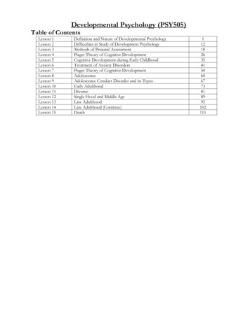
CTMGTPVNational Aeronautics and Space AdministrationOrbital Sciences Corporationprobability of survivalPluto fast flybyquality assuranceresidual gas analyzerradioisotope thermoelectric generatorsmall business innovative researchsystem dynamic modelsystem integration contractorStirling radioisotope power systemspace power demonstrator engine110 W Stirling radioisotope generatorSuperconductor Technologies Incorporatedtechnology demonstration convertorthermo-mechanical generatorthermophotovoltaicI. IntroductionStirling power conversion technology has progressed through several distinct phases of development.The well- known history of Stirling shows that it was patented in September 1816 as shown in figure 1,by the Reverend Robert Stirling of Scotland. The timing is remarkable since it preceded the 1824publication of Reflections on the motive power of fire by Sadi Carnot, and the 1849 formulation of themechanical equivalent of heat by James Joule, which laid the foundation for the first law ofthermodynamics (ref. 1). Two key features made the early Stirling engines attractive in the decades thatfollowed. First, they provided greater efficiency than the steam engines that were in common use. Earlypublished reports documented the efficiency of Stirling engines by measuring the consumption of coalrelative to shaft power produced. The second feature was the safety that they provided. A rigorous boilercode to guide the design of pressurized systems had not been developed. Furthermore, a strict qualitycontrol system within the steel foundries had not been established, thus allowing the materials used inboilers to vary widely in material properties. This resulted in numerous boiler failures and accidents thatposed hazard to personnel as steam engines were in wide use. The Reverend Stirling was motivated toFigure 1.—Drawing from the 1816 patent of theeconomizer. The original patent was for theeconomizer, which operated in the closed cycleengine.NASA/TM—2007-2148052
work on his engine in part due to the concern for the safety of the members of his parish. The earlyStirling engines were closed cycle, and operated with air as the working fluid at atmospheric pressure,which resulted in relatively large cylinders compared to steam engines. This was offset somewhat by thelack of a boiler separate from the power-producing cylinder. Stirling engines enjoyed commercial successand were commonly produced in the range of 0.2 to 4 kW (0.3 to 5 hp). John Ericsson developed a variantof the Stirling; an open-cycle regenerative engine that exhausted the working fluid rather than cooling it.A four cylinder marine engine was built in 1853 that produced about 220 kW (300 hp) for use in NewYork harbor (ref. 2).Advances in the steel industry resulted in a more tightly controlled product with more consistentmaterial properties. In addition, a rigorous design code was established to guide the use of steel inpressurized systems and enhance safety. The design code used safety factors to provide uniform safety inboilers and piping, and included compensation for the known variation in material properties produced bythe steel products of that era. This resulted in relatively safe, high-power steam engines being readilyavailable from numerous manufacturers. Designers were able to push power density of steam engines tohigher levels, ultimately resulting in the demise of the Stirling engine. Internal combustion engines weredeveloped by the mid 1800s, followed by the invention of the electric motor later that century. By theearly 1900s, the first general phase of Stirling development had ended.This status did not change until the 1930s when pioneering research began at Philips Laboratories ofEinhoven, Netherlands, which dramatically advanced the state-of-the-art. The contributions were inseveral distinct areas with great impact on performance, the first of which was operating the cycle atelevated mean pressure. An atmospheric Stirling engine moves the power piston back and forth by raisingand lowering the working space pressure above and below the surrounding atmosphere. A standardfeature of the Philips designs was that they operated at elevated mean pressure, thereby increasing thepower density of the engine. Either the engine could be charged to the desired elevated operatingpressure, or it could be built with a compressor that would pump up the pressure of the engine as itoperated. This required the crankcase to operate at elevated pressure, or it required the working space tobe sealed from the crankcase by a seal that could maintain the difference in mean pressure. Severaloptions for linear seals were developed including the rollsock, commonly used by Philips, or the pumpingLenningrader seal later used by United Stirling.The second major contribution by Philips was the use of gasses other than air as the working fluid.Significant increases in power and efficiency were found to be available in engines with helium orhydrogen as the working fluid. However, the initial interest in low molecular weight working fluids didnot come from engine research, rather it came from the development of low temperature coolers, theyswitched to hydrogen because it offered greatly reduce flow losses, and provided higher heat transfer ratesto increase operating speed. By 1954, they succeeded in liquefying air. Both gasses improvedperformance in engines but presented challenges in containment of the working fluid with hydrogenproving to be more difficult than helium since hydrogen could more easily permeate through polymer orings and in some cases, through high-temperature heater tubes.The third contribution by Philips was perfecting the regenerator to increase cycle efficiency. Theregenerator is a porous matrix that absorbs heat from the working fluid when it flows from the hotexpansion space to the relatively cool compression space, and returns the heat to the working fluid whenit moves from the compression space toward the expansion space. An optimized regenerator will transfermany times more heat into and out of the working fluid during each thermodynamic cycle than the formalheater and the cooler. Philips developed techniques to test and fully characterize the performance of aregenerator, and perfected fabrication techniques of regenerators. It is interesting to note that the earlyengines developed by Reverend Robert Stirling more than 100 years earlier, had a form of a regeneratorknown as an “economizer”. This was one of the most important features of the invention, and was likelyconceived by intuition. One of the applications envisioned by Philips was a portable generator. The earliersingle-cylinder engines had a single crankshaft, but later versions used a dual-crankshaft, rhombic drivemechanism that resulted in linear motion of the piston, displacer, and their supporting rods. This wasimportant as it eliminated side loads and permitted the use of seals to keep crankcase oil out of theNASA/TM—2007-2148053
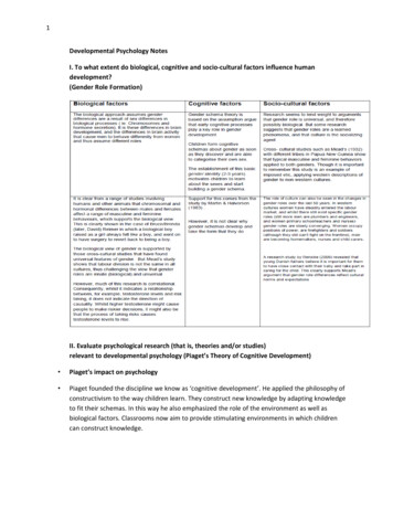
Figure 2.—Philips generator set.Early generator with kinematicair engine, air pump showing onright.Figure 3.—GPU-3 Under test at NASA GRC. TheGPU-3 was tested with hydrogen and helium toprovide data for validation of Stirling cyclemodels.working space and the high-pressure working fluid in the working space. One of the most highlydeveloped single cylinder generators was the GPU-3, developed by General Motors (GM) for the U.S.Army as a fully integrated, 3 kW portable generator. An early generator with a pressurized air engine isshown in figure 2, and the stripped down, rhombic drive GPU-3 is shown in figure 3 being performancetested at the National Aeronautics and Space Administration (NASA) Glenn Research Center (GRC)(ref. 3). The work at Philips continued into the 1980s resulting in highly developed kinematic engines,which depended on linkages, seals, lubrication systems, and resulted in rotary shaft power output.GM actively worked on developing Stirling technology from 1958 through 1970 (ref. 4). Theirinterest dates back to 1947 after reviewing papers that had been published by Philips. They believed thatthere were applications for the technology for marine applications, particularly for submarine propulsion.Initially, Philips did not believe that their technology was ready for the applications targeted by GM,therefore, a licensing agreement was not signed until 1958. They actively pursued applications such asmarine propulsion, locomotive power and generator sets, as well as military and space applications. Theyfound no interest expressed by anyone for road vehicle power even though the Philips data showed over30 percent brake thermal efficiency, and mass that was approaching the Diesel engine. Since Philips haddemonstrated high efficiency, GM focused its’ efforts on seals, cost reduction, analytical modeling, andcombustors. GM received considerable encouragement from the U.S. Army, Ft. Belvoir to develop aStirling outboard motor and small generator sets which would be nearly silent. The licensing agreementwith Philips lasted through 1968, and without having achieved commercial success, development ofStirling technology at GM was terminated by 1970.One of the applications envisioned for Stirling at that time was an automotive engine. Efforts todevelop automotive engines continued at low levels and were often motivated by the multi-fuelcapability, quiet operation, low emissions, and increased efficiency. Other features were that the engineneeded no muffler, no catalytic converter, there was only one igniter, and there was no need for an oilchange over the life of the engine. Interest in the automotive Stirling engine increased sharply in the1970s, motivated in the U.S. by the energy crisis. The most successful advanced heat engine effort wasthe Automotive Stirling engine project funded by the Department of Energy (DOE), managed by NASA,with prime contractor Mechanical Technology Incorporated (MTI) of Latham, New York. Initially, FordMotor Company worked on a parallel effort, partnered with Philips on a four-cylinder engine designatedthe 4-215 that produced 127 kW (170 hp) and used a swashplate drive mechanism rather than theconventional crankshaft. After approximately 1 year, Ford made a corporate decision to discontinue theirinvolvement in Stirling to focus their resources on a lean-burning Otto cycle engine. MTI partnered withUnited Stirling of Sweden, and developed engines evolving from the four-cylinder, dual crankshaft P-40NASA/TM—2007-2148054
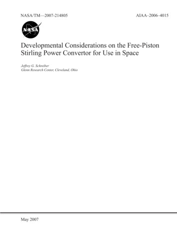
design. By the mid-1980s, several generations of engines had been developed resulting in the Mod IIengine, which was a single crankshaft, V-4 configuration (ref. 5). The goals had been achieved ofincreasing power, reducing manufacturing cost, reduce start-up time, and improve throttle response.Engine efficiency was over 38 percent. A manufacturing study concluded that production cost would beless than a comparable Diesel engine. Early vehicle tests used American Motors Corporation Lerma andSpirit, which logged 2,300 and 13,763 miles respectively. Engines were integrated into threedemonstration vehicles, which were put into service, two by the U.S. Air Force and one by the U.S. PostalService. An automotive Stirling engine is shown in figure 4 integrated into a D-150 pickup truck. Theengine resulted in a 10 percent improvement in fuel economy compared to spark ignition engines of theday, with emissions that were lower than the most demanding standards that were being planned. Theresults of the field trials were positive, with the Air Force van logging more than 1429 hr of operation andover 8,800 miles on JP-4 fuel, Diesel fuel, and unleaded gas. The D-150 pick up truck logging over1,200 hr on the road, and more than 20,000 miles. The postal vehicle was used in daily service for a3-month trial. Other technologies advanced during that time and the price of fuel stabilized, reducing thewillingness of industry to brace this new technology.Derivatives of the Philips technology have continued to be developed for applications such asstationary power cogeneration, waste heat utilization, and for biomass systems. The United Stirlingtechnology has also continued to be developed with its’ most common use in submarines. Most of thekinematic engines are four-cylinder Rinia engines, in which there are four Stirling cycles operatingbetween the four double-acting pistons. Although there is some ongoing development of kinematicengines, the great advances mentioned thus far can be viewed as the second general phase of Stirlingdevelopment; maturing of the kinematic engines.Although there are references to a resonant Stirling device dating back to the 1940s at Philips, theinvention of the free-piston Stirling is accredited to William Beale, founder of Sunpower of Athens, Ohioin the 1960s, when the hardware was first operated successfully. The free-piston Stirling is a resonantdevice whereby the motions of a piston and a displacer are guided by spring-mass-damping systemdynamics. Very generally, the total spring content comes from several sources including internal gassprings, mechanical springs, and other sources of spring that are inherent in the dynamic system, masscomes from the moving physical components, and damping comes from internal flow losses or the loadfor the power output produced. Development of early free-piston Stirlings focused more on mechanicalconfiguration, dynamics, reliability, and performance, but paid less attention to the conversion of linearmotion to electricity or some other useful form of power output. The potential of free-piston Stirling for arange of applications was recognized by the 1970s resulting in the early research efforts for applicationsFigure 4.—Stirling engine in D-150 pickup truck.This truck was put into regular service at severalAir Force bases and was driven across theUnited States.NASA/TM—2007-2148055
such as terrestrial generators, heat pumps, or space power conversion. As the technology was in its’infancy, much of the effort was spent on getting the hardware to operate reliably, as intended, and at fullperformance. All of these were at power levels of 5 kW.By the 1980s, free-piston Stirling technology had evolved to the point where the intendedperformance of a new engine design could be achieved after a reasonable amount of development.Integration had improved and the designs were becoming more compact and more efficient. Theintegrated free-piston Stirling engine with a linear alternator converts heat to electric power and hadbecome known as a Stirling convertor. NASA had interest in Stirling power conversion since the 1970s,envisioning that the technology could someday be developed into a long-life, high-reliability device. Oneof the motives for being involved in the automotive Stirling engine project was to gain expertise and helpadvance the technology, although it was generally thought that the kinematic designs would be verydifficult to integrate into a space power system due to the mass and complexity of the linkages. Thebearings, sliding seals, and other associated mechanisms were all subject to wear, and are therefore lifelimiting. The automotive engines, for example, had a design life of about 1,000 to 2,000 hr.The emergence of free-piston technology resulted in MTI being commissioned to design the SpacePower Demonstrator Engine (SPDE) and the Component Technology Power Convertor (CTPC) for theSP-100 project. The SPDE was intended to demonstrate the feasibility of free-piston Stirling powerconversion for a 100-kWe system that would use multiple Stirling convertors, heated by a nuclear reactor.The SPDE, shown in figure 5, produced 25-kWe output with conversion of heat to electricity at about20 percent efficiency when operated at a temperature ratio of 2.0 (ref. 6). It was a symmetrical designwith two displacers, two power pistons, and two linear alternators, sharing a common expansion space.The SPDE was a dynamically balanced unit showing negligible vibration. It had hydrostatic gas bearingsfor non-contacting operation, eliminating any wear mechanisms, thus enabling long life, limited only bythe creep of the heater head. It converted heat to electricity at a fraction of the Carnot efficiency, higherthan the alternatives. Since it was intended to demonstrate feasibility, the SPDE was built with materialsthat limited the hot-end temperature to about 630 K (357 C). The CTPC was then built for similarperformance as the SPDE, but with capability to operate at temperatures more representative of a nuclearsystem. The hot end of the CTPC was designed to operate at 1050 K (777 C) with the cold end at 525 K(252 C) with a design life of 60,000 hr. The heater head was designed to be fabricated from Udimet 720,however, due to programmatic considerations, the CTPC was fabricated out of Inconel, which limited thelife at the full design temperature. The CTPC generally operated as intended and did not require anyCold sectionsHot sectionsLinear alternatorsFigure 5.—The Space Power Demonstrator Engine.The first dynamically balanced, dual-opposedfree-piston Stirling convertor with non-contactingoperation. Approximately 1.3 m (53 in.) in length.NASA/TM—2007-2148056
additional development effort. When the SP-100 and follow-on Civil Space Technology Initiative endedin the early 1990s, the CTPC had operated slightly more than 1,500 hr.Other free-piston Stirling convertors were being developed at the same time, often trying to findsuccess in a commercial niche market. Trying to capitalize on the investment being made by the SP-100project, the Advanced Stirling Conversion System project was conceived to develop a 25 kWe solar-toelectric conversion system. The goal was to develop a system that would be cost competitive as itsupplied power to the utility grid, and would include the solar concentrator, solar receiver, free-pistonStirling convertor, and necessary support equipment. The intended life was 60,000 hr over a 30-yearperiod, with one rebuild permitted (ref. 7). It was believed these goals were now achievable by theemergence of free-piston Stirling power conversion which was now sufficiently mature since powerlevels had reached 10’s of kW, efficiencies were high, non-contacting operation had been achieved, andlife limiting wear mechanisms had been eliminated by design. Several prototype systems were built andtested, however commercial success was not achieved. The SP-100 convertors represented the state-ofthe-art of the technology in the early 1990s. Convertors were being built that were more compact,operated more reliably, and achieved intended performance with minimal development. This can beviewed as a third phase of Stirling development whereby free-piston Stirling power conversion is able tooperate at the intended level of performance, albeit sometimes needing a little refinement following initialoperation to achieve full performance, but to a great extent still lacking in system integration.II. Stirling for Radioisotope Space PowerNuclear and solar thermal power systems in space are generally considered to be in the range ofmultiple kW’s. Radioisotope power systems are commonly considered to be at lower power levels,generally at 1 kWe. Long life and high reliability are the most basic requirements for space powerapplications regardless of the power level. While feasible, these requirements present a challenge for theuse of dynamic power conversion in space. Highly developed kinematic Stirling engines with rotaryalternators had been studied for radioisotope space power by General Electric and Philips in the 1970sunder contract to the DOE (ref. 8). The Stirling Isotope Power System (SIPS) was designed to delivermore than 1 kWe with system efficiency of approximately 28 percent. Operation was intended to becontinuous and unattended for a period of 6 months with only routine maintenance between operationperiods. The system was designed for a total useful life of 10 years, with one major overhaul permitted.The engine used the dual-crankshaft rhombic drive mechanism that has timing gears and a minimum offour connecting rods, two rotary alternators, an oil-lubricated crankcase, polytetrafluoroethylene Teflon(DuPont) piston rings in contact with the cylinder, and a “scraper-type” oil seal to keep the oil in thecrankcase. The engine, shown in figure 6, was pressurized to approximately 9.53 MPa (1380 psia) withhelium and operated at 1950 revolutions per minute. Development of this hardware needed to considerhermeticFigure 6.—Kinematic radioisotope Stirling generator.Stirling Isotope Power System (SIPS) with rhombicdrive Stirling and two rotary alternators.NASA/TM—2007-2148057
containment of high-pressure working fluid, isolation of oil from the working fluid, wear of sliding seals,and two-phase fluid management within the lubrication system. There were numerous metallurgical jointsin the pressure boundary that consisted of 12 heater tubes, 6 regenerators, and 117 cooler tubes. The heatsource provided 3930 W thermal at beginning of mission (BOM) and the nominal operating temperatureswere 750 C at the hot end and 50 C at the cold end of the cycle. The project resulted in hardware beingtested.With the advent of free-piston Stirling, an alternative became available with potential for long life,high reliability, high efficiency, and reasonable mass. The key features that made it attractive were theelimination of all wear mechanisms by design, elimination of seals, valves and the lubrication system, andthe ability to have a dynamically balanced system. Studies were performed as early as 1989 at NASAGRC to determine the feasibility of free-piston Stirling power convertors in a high-efficiency radioisotopepower system (ref. 9). The two systems studied used either 4 or 8 General Purpose Heat Source (GPHS)modules with electric power output of 240 and 480 W, respectively. Specific power was projected to be7.1 W/kg for the lower power system and 8.0 W/kg for the higher power system. One of the applicationsfor which the generator was proposed was for robotic missions such as planetary rovers. While this wasan initial study, lacking some of the details needed in flight development, it did indicate that the conceptof a free-piston Stirling radioisotope generator was feasible as a high-efficiency, long-life powergenerator with a competitive mass. The designs and analyses were refined by subsequent studies thatevaluated a range of applications (refs. 10 through 13), and at the conclusion; generators were proposedover a power range of 200 to 600 W power output with specific power ranging from 5.4 W/kg for thelower power level to 8.7 W/kg for the higher power systems. As shown in figure 7, the layout placed theGPHS modules around the perimeter of the Stirling heater heads, and each convertor had two pistons andtwo alternators such that each Stirling would be nearly balanced dynamically. By the early 1990s thepotential had been recognized, however, there were deficiencies in the development that remained to beaddressed; namely, development at the power levels of interest, system integration, and the need todemonstrate the life and reliability through conclusive data.An early effort to address the Stirling convertor design came from a 1993 NASA Small BusinessInnovative Research (SBIR) contract with the Stirling Technology Company (c
Developmental Considerations on the Free-Piston Stirling Power Convertor for Use in Space Jeffrey G. Schreiber National Aeronautics and Space Administration Glenn Research Center Cleveland, Ohio 44135 Abstract Free-piston Stirling power conversion has been considered a candidate for radioisotope power systems for space for more than a decade.